Did you compare input amps between the two batches of cells? The driver output should be the same with either, so with higher voltage from the better cells the input amps should be lower. Same thing you found when improving connections at the springs - tailcap current dropped, because efficiency improved. The driver will only take as much as it needs to maintain the output level set by the sense resistors.
That would require me remembering something! But of course you are exactly right, the tailcap amperage went down to 2.44A for an effective emitter 4.588A. Still not shabby and an overall gain of some 300 lumens for adding 3 little tiny resistors at $0.63 ea.
Thanks for keeping me going the right direction. Again. ![]()
With the Protected AW’s fitting the carrier better, and the Samsung 20R’s being on the short side. Which chemistry would be the best to stay with? The Samsungs are going to give a better discharge curve by a fair margin. But are they as safe? This light has over-discharge protection on Hi and Med modes. I’d be giving up 600mAh capacity with the Samsungs. Without knowing about the safety difference between INR and Li-Ion standard Protected I don’t know if the Pro’s outweigh the cons.
Nice work.I’m getting one.
Now can you figure out how to put that 2200 head on my gladiator body? LoL
I can’t leave anything alone, and the capacity in the S2200 just got to me…so I added 2 more of the resistors…one at a time…and took measurements. Starting now with 3 stacked resistors at 2.49A I added one and got 2.63A. Added a second (last one I had, for a total of 5 stacked 1 ohm resistors) and got 2.77A at the tail. This adds up to something like 4.86A on the MT-G2 emitter for an estimated 2780 lumens. ![]()
Ok, I can stop now! ![]()
{11.27V(3 AW 2600mAh cells on V sag running Hi) * 2.77A = 31.22W / 6.42Vf = 4.86A to the emitter}
Here’s the S2200 with the 1st mod, 3 1ohm resistors for a tail reading of 2.49A

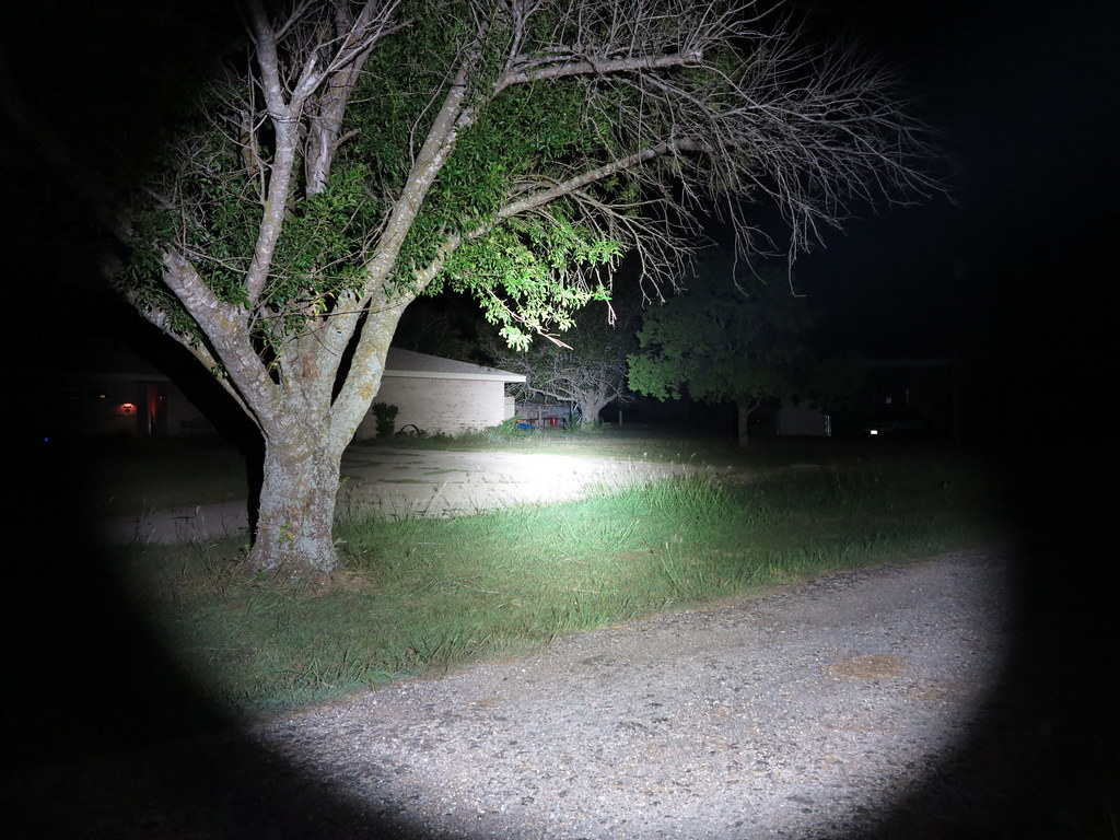
And tonight, with 5 resistors total and a tail reading of 2.77A
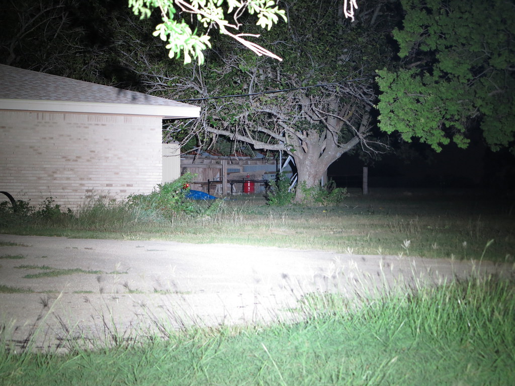
Wide angle vs wide angle, 1st mod then 2nd mod

Amazing build. I’m still reading through all of this but have you tried it on IMR18500s or IMR18350s. Could be a real pocket rocket.
skyrider, it’s pretty cool with 18350’s but of course pulling nearly 5A at the tail doesn’t allow them to run very long. Tonight I double checked and it’s running 4.83A on 2 Samsung 20R cells fresh off the charger. That translates to 6.04A to the emitter for 3100 lumens, give or take.
It do get hot! ![]() Which will be nice this winter, this summer…not so much.
Which will be nice this winter, this summer…not so much.
Couldn’t you maintain reverse polarity protection in your mod by instead of replacing the zener diode on the + lead with a resistor, simply soldering a 200 ohm resistor in series with it?
Also, i haven’t torn my K3 head apart yet, but is the brass driver bezel you are using something that came out of the original light? I assume if so, that it was there to provide an electrical soldering path for the driver ground.
Thanks!
The Zener limits Voltage to the MCU so that 2 Li-ion cells in series at 8.4V don't fry the brains. ;)
caall99, there is no brass driver bezel...wasn't one and still isn't. I made a copper pill/heat sink using 3 ounces of copper at 7/8" diameter and 1 1/16" long. I recessed the back end of that copper rod to accept the driver.
There is a 200 ohm resistor at the positive lead to the emitter, the Zener is stacked on the capacitor on the other side of the board, the spring side.

Wow pretty photos ![]()
Thanks for sharing!
-Jamie M.
Thanks Jamie
As a side note, I now have a lightbox thanks to my good friends manxbuggy1 and rdrfronty, the K3 is making 2412 lumens OTF at 30 seconds pulling 4.76A from 2 Samsung 20R cells. Start-up shows 2495 lumens. And the 2 20R's let it drop like a stone in a pond. :) Need some higher capacity high discharge cells, will probably get more Panasonic NCR18650PD's.
Nicely illustrated…clear explanation…well done!
I just took apart my K3. The MCPCB looks pretty copper to me. What about it is faux copper? Wondering if i should put it back in vs using my Noctigon MT-G2. Any last minute recommendations?
The Solarforce "copper star" has a dielectric layer between the thermal pad and the copper base, so it's not a direct-to-copper heat transfer from the emitter through the copper you see. If you re-flow the star and pull the MT-G2 off of it, you can put your DMM contacts on the copper/thermal pad looking for continuity and you won't find it.
Comfy and myself have both sanded down the layers of the star and found the copper trace that the thermal pad of the emitter sits on disappears! Sanding down further through the dielectric layer gets you down to the copper. This is a layer of, essentially, fiberglass. An insulator.
The Noctigon is direct-to-copper thermal transfer, the only way to go! ;)
Thanks so much for the quick reply! Will proceed with noctigon!
How about wire thickness? I have some 18 and 22 AWG silicone wire that i was thinking of using between noctigon and driver? Is the QLite wimpy wire sufficient? It seems rather short as well…
I could also use the wires that came with the K3 head in the first place. Look to be about 22AWG or 24 AWG.
Go with the 22, 18 will be hard to fit on the driver.
Ugh… no 22… i lied. But i am going with 24.
Plan is to Fujik the Noctigon to pill? Is this permanent?