Also thought about that he wrote that the Tail LED did not lit up with a resistor above 200 Ohm, this would mean that R1 or R2 might be broken or have a cold solder connection
Signal current and MCU power are totally different stories
A 4 core CPU with 100W power has about 1.000.000.000 transistors
So each transistor has a power of 100nW at 1.2V, this is the power loss over the whole transistor, the gate current is only a fraction of it
What the actual current on Pin7 is you can likely look at the tiny85 datasheet
Lets say it has 1M Ohms resistance and you got like 40-300mV on R2,
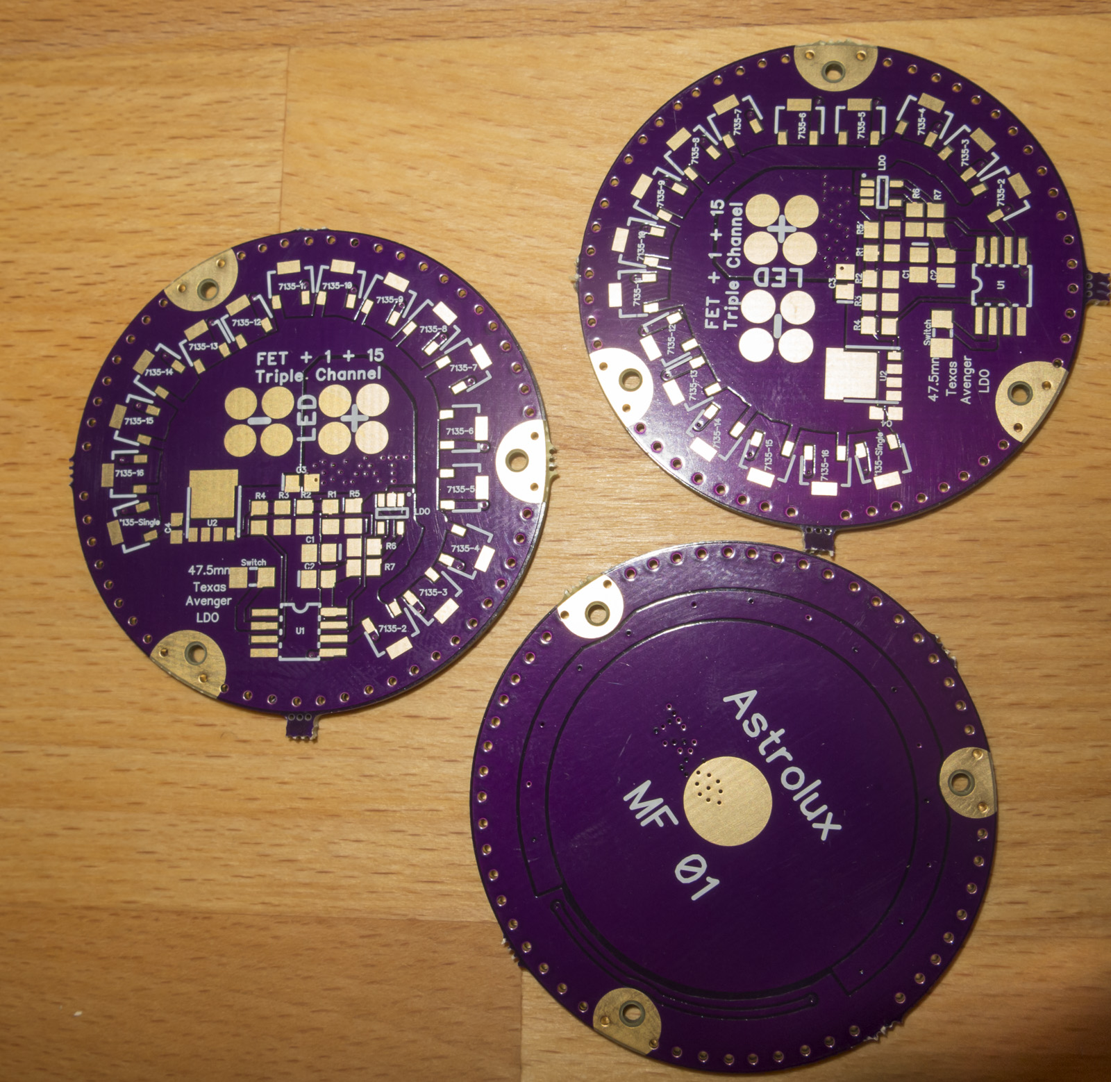
Again no ground rings
for the people with MF01 drivers 2 things to get it fixed
I try to get Oshpark do them right which adds 3 weeks and I am note sure if they get it right this time
or
I add a thin layer of solder which I sand plane so that the 3 spots around the holes get higher than the solder mask to make contact to the brass ring
in this case when I get a refund from Oshpark I refund you 3.35$ per driver
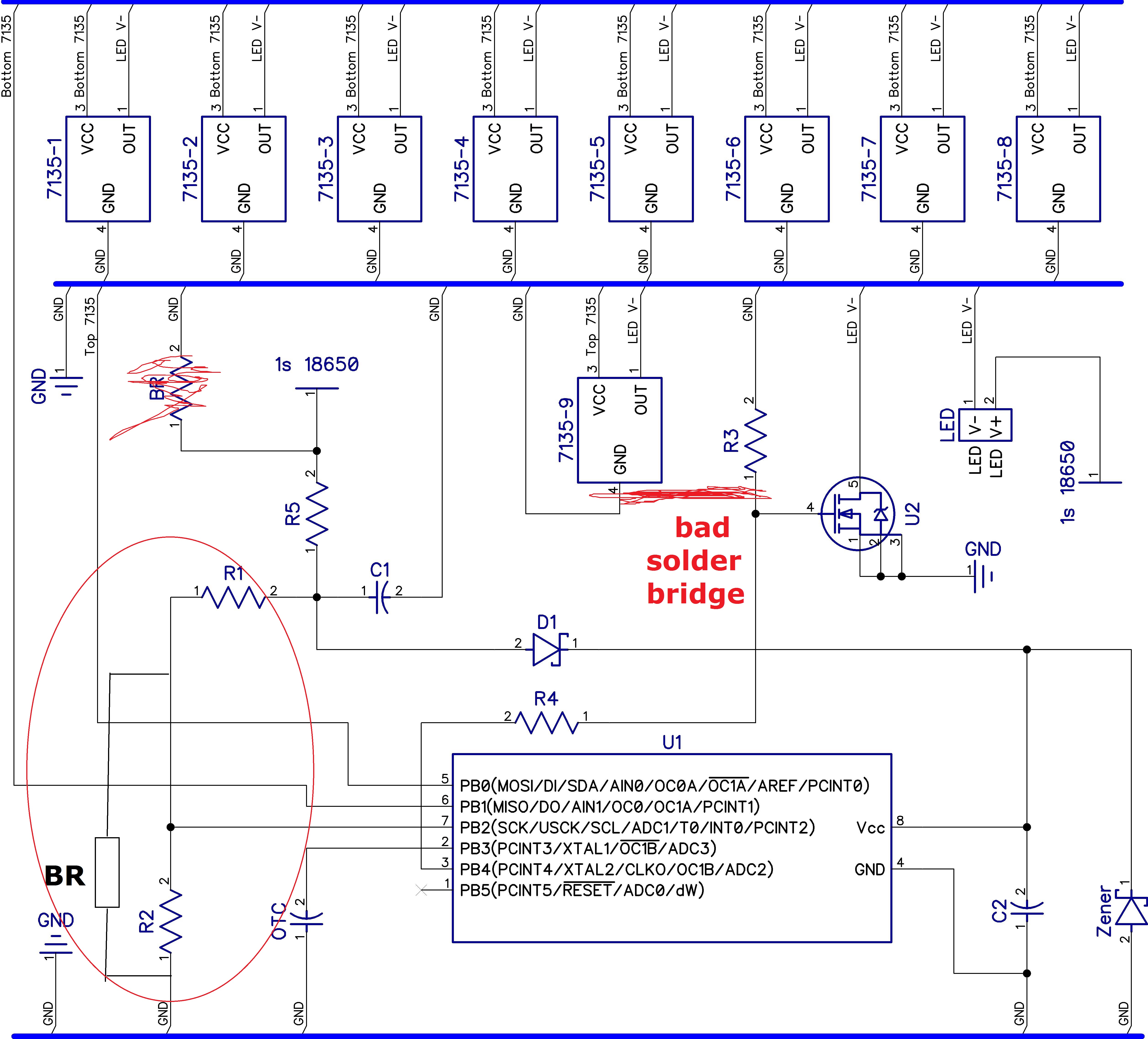
the solder bridge from the 7135 to the FET gate resistor is bad, you got to remove this
you basically short the single 7135 output directly with the FETs gate
.
The 01b on R1 is right it is a 1k Ohm 1%
R2 is 3.3kOhm
your reading are both correct for the used resistors
it sounds not logical, but R1 and R2 have both a 1kOhm bleeder resistor parallel
I ignore the 4.7Ohm calculating it correctly it is too small anyway to have any impact
just look on the circuit diagram
so if you are measuring R1
so you measure 1kOhm with 3.3k+1k parallel to it
the value should be 767 Ohms
if you measure R2
you have 3.3kOhm and 1+1K parallel to it
the value should be 1245 Ohms
so far so good, to get the real deal would be to measure the voltage on R1 and R2 on the side towards the MCU
when the light is on you should have about 3V with full battery
shortly after you switch the driver off you should have about 0V
I would add solder MCU pin 7 to be sure there is no cold solder joint and measure the voltage there as well
your current measurements show that when soldering on the BR you disconnected it
Remove it completely and solder 470 ohms across C1, same electrical connection,
but a with a fitting 0805 pad and no other parts making it harder to solder it
now 100% of the tail LED current flows through R1 and R2 messing with the offtime detection, so the driver thinks its not shut down because too much voltage drop over R2, you have to get below 0.6V to get a safe OFF detection
The bleeder is necessary for OTSM to bypass R1 and R2 when the light is off to a certain degree
there are just fast and medium presses in Bistro, if it advances to lowest mode it counts as shutting the light off for a while
if the Bleeder is 1K its just 19% and you are fine
if you have 1kOhms Bleeder the tail resistor should be 3-5 times bigger to be balanced
next time just tell me you want a BR on the driver when I send it to you and you got it,
without the risk messing it up and I test it with the resistor on it
I’ve resoldered BR (1K) and put in tailcap 2 pairs of green led + 4.7K. Seems to be working, but when I reassembled the light, I could not change modes. Probably something touches copper part, because when loosened retaining ring, everything is back to normal (possible to change modes in both directions and green leds are on). Tomorrow I will use kapton tape to isolate elements on the board.
never mind, too busy to follow closely, but lexel's points have all sounded fine, just read your last post g_damien, and deleted my other details, as they aren't needed now. It seems like you've got it about tracked down. Glad it's working out.
"there are just fast and medium presses in Bistro, if it advances to lowest mode it counts as shutting the light off for a while"
Yes, but this often gets loosely referred to as a long press as it sometimes gets used like one, precisely to return to the lowest mode. In fact in HD a long press triggers from either a full power off or from exceeding the time threshold, even before full power shutdown occurs, so it's configurable up to the hardware limit. It was also configurable in OTC for that matter too but it was programmatically identical to a full power off in that case. It's not in HD.
The bleeder isn't needed if you use R1 and R2 totaling about 1kOhm (811 Ohm would be exactly equivalent actually). Yes all the current will flow through R2, but I x R2 is compensated by lower R2 so voltage drop is the same, and total effective resistance and total current are also the same. So long as Reff is the same and Rled is the same, voltage drop on R2 is the same. But it doesn't matter. Either way works.
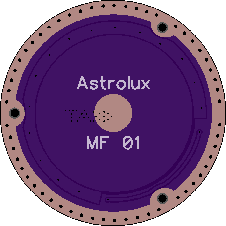
The problem with missing ground rings should be fixed for my drivers, as first I have the knowledge that the fab with super swift service does not has this issue.
And the cause was Texas_Ace´s too big solder mask clearance caused this issue on the slow fab, as it collided with the boards around and got deleted automatically.
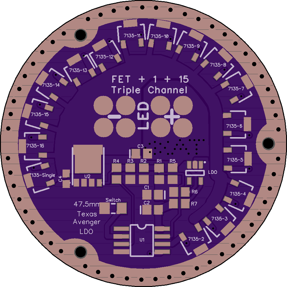
New design of TA boards I have made fix this issue on all sizes.
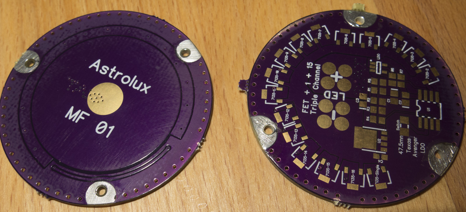
left new designed ground ring does not exceed the board outline anymore
Two quick questions, may already been answered, but I am working and havent had enough time to look through all 12 pages thoroughly yet. I will do so when I get home.
1) I see this driver can do lighted switch and battery voltage indicator blink (w/o calibration). Can it do both on the same light ? (preferably w/bat. indicator led only when light is on)
If so, I am thinking this could be done either….
….A) by having only one led in the switch for each function, one say red and the other blue ?
…….B) machining a spot for the voltage indicator LED in the body or head somewhere
2) 30mm still available as follows ? unsure of wire length for main LED as I do not have the host in hand yet
……. 1) 30mm , 2s , NarsilM , LDO , No Calibration , PO=NO , lighted side switch , Convoy L6 , with LED wires ( ? possible separate bat. voltage indicator light ?)