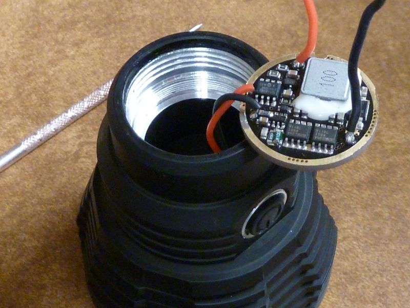
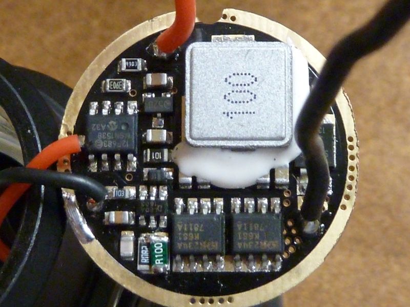
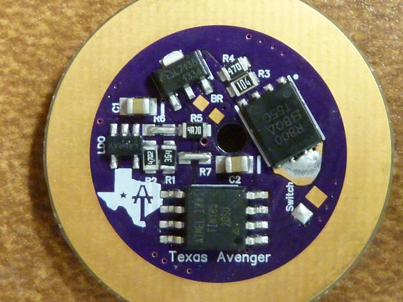
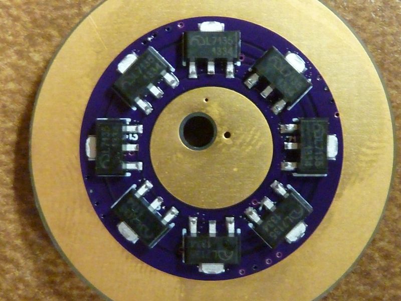
Boards have arrived for Small Sun ZY-T08 MT-G2 mod. Now I have to wait for the components.

Looks great! can’t wait to see it put together. The size came out correct?
My 30mm and 22mm LDO board shipped Tuesday, so another couple days. The 30mm I believe is for the L6 - look' forward to that one.
I finished one with a kiribi.ru copper pill (nice) and piggybacked an LD-4B with MT-G2. Would really be nice with this driver. Beautiful work on these boards TA!! ……plus ZozzV6. Thanks for posting and pic
Yeah, I keep wanting to build an L6 driver but have not had time to finish looking into the china PCB houses to see which ones I wanted to order from and how to order them.
Although I did get in a few 17mm PCB’s and a stencil to make putting them together a bit easier. I plan to make a small batch of them as a test run and list them for sale.
I know this was discussed a while back about using 7135's in zener or LDO modded 6V setups, concluding it's ok up to 6V or so, but just came across this post from Richard in the H17F thread:
You could zener mod it, but you'll burn up the 7135 chips, especially the single channel 7135 chip, in a hurry. Not recommended. The duty cycle would have to be greatly reduced on the single 7135 chip, which would require a firmware change
https://budgetlightforum.com/t/-/36651/217
Not sure if duty cycle means PWM rate? So he's saying it's possible, but by reducing the duty cycle which I don't know what it means. I'm asking because I received the 30 mm LDO OSHPark TA boards, and am prep'ing one for use in a L6, and if his comment applies to this board as well, sounds like trouble...
The H17F is a triple channel board, but I see uses the 380 mA 7135's, not 350's that I'm using.
Richard is the main voice against 7135’s with anything higher than 1S cells. He’s actually the only voice I’ve heard, but he says it is feedback from his customers. Other people have said that the 7135’s seem to throttle themselves down when they are too hot, but no permanent damage.
I have run a few lights with 7135’s driving an MTG2 or XHP70 or even triple XHP50 at 100% duty cycle (255 PWM) and although they weren’t used extensively, I have seen no sign of failure even with the terrible heat properties of stacked chips. Plus people were zener-modding Qlites for a long time before we started these other drivers.
I think someone needs to test and publish data to set the record straight, but I have neither the time nor the equipment.
Weird - he's say'n the single channel 7135 would burn out in a hurry - sounds like directly from experience. Maybe it's the 380's? Yea, direct conflicting experience/info. Hhhmmm....
If the 7135’s are not properly heat sinked (not sure what they driver looks like), then yes, they will overheat at anything over 1S voltages if used at 100% duty (yes, that means 255 pwm).
That said the 7135’s are pretty good at throttling themselves in order to prevent damage from what I have read and the end result is simply less output.
In properly heat sinked setups I have never seen anyone but richard say they have killed a 7135, just some say that they drop output.
Either way, the 7135’s are mainly an option on those drivers because there is room for them.
They can be used for moon mode for sure and if you limit the duty cycle and make sure the driver is properly heat sinked to the flashlight I see no reason that they would not work for a low and medium mode as well.
That said I do not know how they will handle 100% duty long term, I think they will live and cause no harm, but I do also think there is a high likely hood of them throttling the output to keep from overheating.
I want to build a 2S driver and test it for myself. I might actually have an excuse to do that when I test the XHP35 with PWM before long. Just got to wait for the LED and the 25V C1 to show up.
But isn't that a 4S setup for an XHP35?
Yeah but once it is zener modded it doesn’t matter what voltage I put into it ![]()
I will have the zener modded driver built that I can then play around with for other projects. Although in theory the 7135’s would work for moon mode even with 4S but they will most assuredly overheat at 100% duty.
Hi!
It almost fit in the Zy T08. It needs some sanding. Tomorrow I maybe have time for accurate measurements but here is a pic of it.

Most likely the slight differences in size the oshpark has with their PCB’s. They are generally slightly different then what I measured in diptrace, possibly due to them trying to not have the copper so close to the edge.
Luckily that should be pretty easy to sand down.
I will look at updating the PCB to slightly smaller to account for this once you take some measurements.
OK, I'm getting closer... Here's the Convoy L6 driver, with the resistor mod. Stock LED wires look like 20 AWG but have thick strands, so the wires are stiffer than that we use. Also they are rated at 150C, not 200C like we use:


Now here's the new L6 driver just reflowed. I buzzed it out and all looks good, first shot. Didn't have 0R resistors so used short wires, cut from resistor leads:


I got R3 and R4 positioned correctly this time ![]() . Ohh, the LDO I'm using is from Richard/MtnE so not 100% sure what it is, but should be an identical one Richard has been using.
. Ohh, the LDO I'm using is from Richard/MtnE so not 100% sure what it is, but should be an identical one Richard has been using.
I was searching for FET and I can’t find a source which has free shipping to Hungary to keep the driver cost low. I searched ebay and Aliexpress too. On Ali I found an NXP PSMN3R2-30YLC instead of NXP PSMN3R0-30YLD which has almost similar datasheet. Is the one what I found will be ok instead of what recommended for these drivers?
Here are the two datasheets:
PSMN3R0-30YLD
PSMN3R2-30YLC
I only found major difference is the 92W power instead of 91W and 3,5mOhm resistance instead of 3 mOhm
Great, can’t wait to see how that L6 driver works! If you don’t have plans for the others let me know, I might take one from you to give it a try, not sure if it is worth ordering a batch to sell or not, I want to see how it works first before I order them to sell. I don’t like selling something I don’t personally use/recommend.
I didn’t take a close look at it but yes, that should work fine, just a bit more resistance then normal. Should be fine for running a single emitter, if you plan to build triples then something like a sir400/800 would be slightly better but honestly even with triples I only notice a fraction of an amp difference in total output between the NXP and SRI800.
I only use the SIR800’s for triple builds personally and not even all of those.
Wired up the driver, bench tested on a XM-L2 on 1 cell and got nothing - no 2 blinks on power up. Not sure if an LDO should function at 4V or not...
Then on a MT-G2 with 2S cells and it smoked - looks like the 4.7 ohm resistor burned. Got to BBQ dinner - will get back to it later.
Odd. Do you have a bench power supply? I would try it without an LED hooked up and slowly increase the power while watching the LDO output to make sure it is outputting the correct voltage to the MCU. Try something like 5-5.5v to start out with.
If the LDO is outputting the correct voltage then it becomes a question of why R5 would have burned. That says that way too much current was passing through it and that would mean the LDO is for some reason drawing way more then it should.
Keep us updated.
Hmm. Replaced the 4.7R, checked, double-checked everything, checked the LED - it works fine on the 2S cells I'm using. Still, the 2nd 4.7 ohm resistor burned instantly.
Maybe it's that LDO I had laying around for so long.
I got 5 of the LDO's I ordered from Mouser, but someone told my they have no polarity protection (I can't tell from the specs - no clue). I did order the LDO's from Arrow you pointed out earlier in the thread, but the order only went in yesterday. Maybe I'll try the Mouser ones, Mfr #: MC78LC50NTRG.
Whoopsie!! Compared the specs on the two LDO's and the pinouts are different!
Here's the Mouser ones I got: http://www.mouser.com/ds/2/308/MC78LC00-D-110708.pdf
Here's the ones you have, that I just ordered: http://www.mouser.com/ds/2/268/mic5235-778645.pdf
The pinout for Vout is completely different! Mine would definitely not work on your board design. Boy, I though the 5 pinners woud map the same. ![]()
You can bypass the LDO by installing a diode across the 2 pins on the far right, closest to R2, with the line pointed down towards the MCU. You could try that with 1S voltage to make sure the rest of the driver works and then you would know if it is the LDO.