Thanks, yes I hope too.
The D4 driver is probably the same size as the D4v2 (22mm) so yes that’s a good candidate.
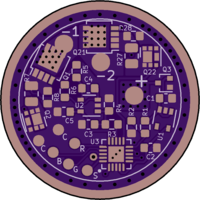
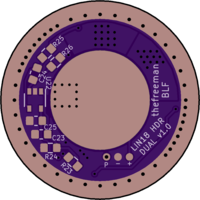
The 0603 sized components on the back (C6, R10, D1) can be hand soldered, I solder SMD components down to 0402 (never tried smaller) like shown in this video , for just 3 components it would probably take a longer time to use hot air anyway.
The most difficult part is the Attiny1616, I reuse a stencil to apply paste just for that part, as buying a new stencils for each drivers would be a bit expensive for me since I do a lot of prototyping.
For the rest of the components I dispense the paste manually.
For manual dispensing I highly recommend to not use big syringe the paste usually comes in, the control is very bad (not enough/too much pressure) instead I use a 1mL syringe with a 25 gauge (red) plastic tip (less resistance than metal tips)
You can buy stencils from OSH stencil after completing the OSH Park order.
It is also possible to reflow the components without using paste and stencils by pre-tinning the pads with solder, clean, re-apply flux, place the components, then reflow on a hot plate. A few pads might not wet properly but that is solved by poking the components a bit during reflow. I used this technique one time with 0402s, SC-70 and a small QFN.
I did reflow two times a 1616 by manually dispensing paste, the first time I put a bit too much paste and couldn’t see if it was properly centered, had to reflow a second time to center it properly, and then clean the solder bridges by draging the iron tip along the pads ( like this ). The second time I put less paste but still had to correct solder bridges. I’m using BiSnAg though and with SnPb it might work better because it flows much better. Only pasting the thermal pad and manually soldering the side pads could also be a solution.
Here is a more technical explanation of the driver and what causes the flash.
To use a car analogy, 1st gear is slow speed, 2nd gear is high speed.
Speed at max throttle on 1st gear = speed at min throttle on 2nd gear.
So you get a nice big speed range by pushing the throttle on the first gear, then instantly throttling down and changing to the 2nd gear, then progressively throttling up again up to max speed.
Except, your brain might tell your foot to throttle down when going to the 2nd gear, but your foot can’t do it instantly (PWM RC filter), so for a moment (~5ms), you’re at full throttle and already on second gear, which on a car would mean a stall, but on the flashlight it goes full output, and that’s quite undesirable.
It only does that when ramping up, when ramping down the throttle is already at minimum before switching to the 1st gear.
A solution is to wait a bit to change gear (HDR FET delay, either hardware with the back components, or software, which I don’t have the skills to implement). Another one is to turn off the transmission for a moment, like a clutch does. (mid ramp blink function, but that only works in smooth ramp mode)
To clarify, there is only one channel, this is different to the multi power channel drivers that use 7135/linear FET and DD FET channels. Again kind of like a car, there is only one engine, the whole speed range is achieved with multiple gears. On a linear driver like this one I could have used multiple channels, on a boost or buck driver through that would be much more complicated and the one engine/multiple gears solution makes much more sense. Here I applied it to a linear driver because IMO it still is a slightly better solution even in that case.


