Deprecated, next version will use the DAC for lower component count.
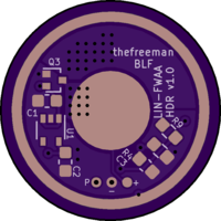
LIN14_HDR & LIN18_HDR linear constant current drivers capable of very low moonlight levels


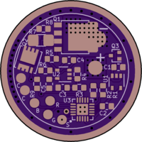
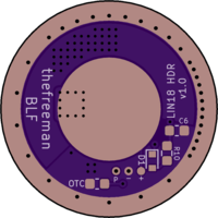
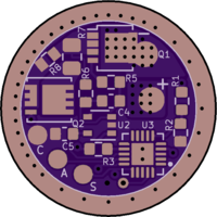
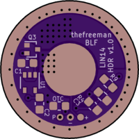
Here are two linear drivers (with super original names) with building instructions, like all the drivers I’m developing they use two current sense resistors to achieve super low moonlight. There is a small one with 14mm clearance and a bigger one with 18mm clearance that can be declined in various final diameters.
I hadn’t planned at first to make linear based drivers but they do have some advantages compared to switching topologies, they require less components, are less costly, can be made more compact and more power dense, easier to build and are guaranteed to be completely silent. Their major downside is the lower efficiency but it is still better than FET direct drive and 7135 PWM drivers.
List of features :
- 14 and 18mm clearance diameter
- Li-ion 3.7V 1S to 1S LED, or 2S to 2S LEDs
- Constant current regulation
- HDR : 1 000 000:1 max dimming range
- Reverse polarity protection
- E-switch Anduril 2
- Attiny1616 : 3 wires flashing, factory calibrated temperature sensor
- 3 AUX LEDs (LIN18), 1 AUX LED (LIN14)
- 10.5mm (LIN18) and 6.5mm (LIN14) spring solder pad
- 0603 passives, one sided(1) (LIN18), double sided (LIN14)
Oshpark links : https://oshpark.com/profiles/thefreeman
Ask if you need other sizes based of those two.
LIN-FWAA_HDR (based on Sunnysunsun measurements)
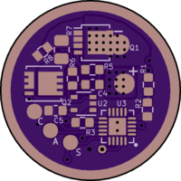
BOM
Capacitors : 0603 X7R or X5R, >10V
Resistors except R7 : 0603, 1%
R7 (LIN14) : 0805, 1%, with sufficient wattage
R7 (LIN18) : 1206 (preferred) or 0805, 1%, with sufficient wattage
Mouser cart : https://www.mouser.fr/ProjectManager/ProjectDetail.aspx?AccessID=8d5e6750d8
(Contains both 0805 (LIN14) and 1206(LIN18) for R7, both R8 values for minimum PWM levels of 1/1023 and 2/1023, both LFPAK33 (LIN14) and LFPAK56 (LIN18) NFET, no OTC)
Configured for 5A:5uA max:min
R1/R2 : 100k, or more, Vbatt voltage divider, internal VREF is modified in fsm-adc.c to 2.5V (1.1V default) to allow R1=R2.
(R1/R2 for 2S : 280k/100k)
R3 : 169k, top R of Vsence voltage divider, Vsense = VCC*R4/(R4+R3), VCC = 2.8V, here Vsence = 53.6mV.
R4 : 3.3k, bottom R of Vsense voltage divider, R part of the RC filter for the PWM signal.
R5 : 3.3k, part of the compensator network for the op-amp.
R6 : 1k, part of the compensator network for the op-amp.
R7 : 8mR, part of HI-Rsense : high current (low value) Rsense, other part is Q2 RDS(ON) (≈2mR) and some stray resistance (~0.5mR).
R8 : 10.7R, LI-Rsence : low current (high value) Rsense.
R9 : 100k, HDR FET gate resistor, R part of the RC delay for the HDR FET, if software delay, replace with 47R-1k
R10 : 100R, C6 discharge current limiter to protect the MCU’s pin, if software delay leave unpopulated.
C1/C2 : 1uF, input and output C for the LDO.
C3 : 470nF, C part of the RC filter for the PWM signal.
C4 : 1nF, compensator for the op-amp.
C5 : 100nF, decoupling for the op-amp.
C6 : 100nF, C part of the RC delay for the HDR FET, if software delay leave unpopulated.
OTC : 1uF, OTC for clicky switch, for e-switch (Anduril) leave unpopulated.
U1 : MIC5365-2.8YC5-TR/MIC5366-2.8YC5-TR , 2.8V LDO, SC-70, 5366 has an additional (irrelevant) function and cost slightly more, choose it if 5365 is out of stock.
(U1 for 2S : NCP502SQ28T2G)
U2 : OPA333AIDCK/TLV333IDCK or MCP6V66UT-E/LTY (untested) , Op-Amp, SC-70, TLV333 is identical to OPA333 but cheaper. (DCKR and DCKT refer quantity per reel, choose the cheapest available)
U3 : ATTINY1616-M , MCU, VQFN-20. (MNR and MFR refer to the temperature range, both are suitable)
Q1 (LIN14) : PSMN2R0-25MLDX, linear NFET, LFPAK33 (3.3x3.3mm)
Q1 (LIN18) : PSMN0R925YLC, LFPAK56 (5x6mm)
Q2 : DMN22M5UFG , HDR NFET, PowerDI3333 (3.3x3.3mm)
Q2 alternatives if DMN22M5UFG is out of stock : SISS80DN (≈2.5mR) or DMN1004UFV (≈3.5~4mR), R7 needs to be decreased by 0.5 or 2mR (see how to configure my current section), both are untested.
Q3 : RE1C001ZPTL, reverse polarity protection PFET, SOT-416/SC-75, can fit SC-89, SOT-523, SOT-723.
(Q3 for 2S input must have Vgs < -10V)
D1 : RB501SM-30FHT2R, Schottky diode, SOD-523, fast discharge path for C6, if software delay leave unpopulated.
Edit : changed R6 to 1k (from 10k)
Notes
Components availability is... pretty bad, the three critical components are the Attiny1616, the Op-Amp and the HDR FET.
- Mouser expects new 1616s in November, Digikey in September and October
- For the Op-Qmp it’s not better, the OPA333 is out of stock until 2022, Mouser has a small amount of TLV333 in stock which won't last long, a few days probably, with a few more coming in November. Mouser had 2000 MCP6V66 a few days ago but they’re gone...
- Mouser was supposed to receive new DMN22M5UFG-7s a few days ago, status is ”pending” not sure what that means.
Because there isn’t full Anduril support for the dual sense resistor circuit, I added components to delay the HDR FET, this delay is needed to prevent a flash when ramping up at the transition of the low and high current ranges. This flash can be hidden by the mid ramp blink but since it blinks only in smooth ramping that doesn’t work for the stepped ramp.
(1)LIN18_HDR is one sided… sort of, only when there is full Anduril support and the back components can be omitted.
LIN14_HDR doesn't have these components so until full Anduril support it is only usable in smooth ramping with the blink.
I haven’t tested 2S operation.
The board I tested was a previous version, 18-22m with a LFPAK33 FET for Q1, with 4 LEDs, high input voltage and in open air (pretty bad conditions), the FET was quite hot so I decided to use a bigger package for the LIN18 version, which should have better thermal transfer to the PCB.
I added a PFET for reverse polarity protection and that’s pretty much it for the differences.

How to configure the maximum current
(hardware, the current can always be lowered in software afterwards)
The max current is configured with a combination of Vsense and HI-Rsense (high current Rsense) :
I = Vsense/HI-Rsense
Vsense is set by the R3/R4 voltage divider, R4 is tied to C3 for smoothing the PWM signal into an analog voltage so it is preferable to adjust R3.
R3 = R4*(VCC-Vsense)/Vsense
With VCC = 2.8V (LDO output voltage)
HI-Rsense = R7 + Q2RDS(ON) + stray resistance
Q2RDS(ON) ≈ 2mR, stray resistance ≈ 0.5mR (traces resistance ≈ 0.2mR, sense resistors measuring a little higher than rated, at least the 0805 ones I have ≈ +0.3mR, hopefully will be lower with 1206 sense resistors)
In general 50mV Vsense is a good value to use
For HI-Rsense I recommend staying above 6mR, this is because Q2RdsON is not as consistent as a resistor, there is some variation between parts and it increases more with temperature.
Example for 6A :
Starting with Vsense = 50mV
HI-Rsense = 50/6 = 8.33mR, let’s chose R7 = 6mR, giving HI-Rsense ≈ 6+2+0.5 ≈ 8.5mR
Now Vsense = 8.5*6 = 51mV
R3 = 3.3k*(2.8-0.051)/0.051 = 177.9k , closest E96 value under that : 174k.
Max power in R7 : 6*6^2 = 216mW
Alternatively we can keep the R7 proposed value for 5A (8mR) and bump the Vsense voltage to (8+2+0.5)*6 = 63mV by using R3 = 140k (Vsense = 64.5mV)
Example for 12A :
R7 = 4mR, HI-Rsense ≈ 4+2+0.5 ≈ 6.5mR
Vsense = 12A * 6.5mR = 78mV
R3 = 3.3k*(2.8-0.078)/0.078=115.2k , closest E96 value under that : 115k
Max power in R7 : 4*12^2= 576mW, use a 1W 1206 resistor.
How to calculate R8 (low current Rsense)
R8 is tied to HI-Rsense and the lowest PWM value used in the HI-range, R8 must be so that the top of the LI-range and the bottom of the HI-range have the same current.
If we use the 1/1023 PWM level, then R8 = HI-Rsense * 1023/1
If we use 2/1023 as the min PWM level, R8 = HI-Rsense * 1023/2… etc.
The reason to not use the lowest PWM level is that in some cases, with a 50mV full scale Vsense, the 1/1023 PWM level can slightly flicker, from the drivers I’ve built it’s not common but I have seen it a couple of times.
So, if the maximum dimming range of 1 000 000 : 1 is preferred, use the lowest PWM level (1/1023), at worst if it is unstable, the bottom of the LI-range PWM level can be configured to 2/1023, while the bottom of the HI-Range stays at 1/1023, giving 500 000 : 1.
If 250 000 : 1 is enough then set the minimum at 2/1023 on both ranges, with R8 = HI-Rsense * 1023/2.
How much current ?
The power dissipated in Q1 is heavily dependent on the Vf of the LED(s) (more LEDs = lower Vf) and input voltage.
The LFPAK56 version should handle any current with 4 LEDs, LFPAK33 any current with one LED, further tests needed to confirm with 4 LEDs.

Assuming a total resistance minus Q1 of 50mΩ (25m cell, 10m springs, 10m HI-Rsense, 5m wires)
