I was pulling 4.73A and had been for some time when I changed my lights layout from 2 18650’s with an extension tube back to the original L2P host with 2 18350’s. The smaller cells would rattle so I knew something was amiss. The spring was partially collapsed and discolored from heat. When I was running the 2 18650’s I was using Panasonic PD’s, they were a bit short so I was using a spacer that compressed the spring…burned or not it was still making contact. The driver end spring is bypassed.
I have 6 lights with McClicky’s, as well as a favorite that I haven’t run with a switch at all as it pulls 11.88A in my preferred configuration. Hedging bets? Neither of you actually has a switch to offer at this time. I’m just wanting my M8 to run at 4000+ Lumens reliably so I can play with it! Matt’s switch should easily handle what I have set up, and then some. Yours is still a question. No reason I can’t set up lights with both is there? I have a light to build for a friend that would employ a triple xp-g2 direct drive on an aw imr18350 for some 7.50A, a little much for the McClicky, a bit too little for the heavy duty smart switch. Yours is perfect for this, and I actually need to build that light twice as my Aunt want’s one as well.
We have Ford, Dodge, Buick and Chevrolet at this house, no loyalty oaths have been taken.
Not an either/or proposition, more of an “and”. BeUTful ain’t it! lol
They have a shunt disk but they wired the spring to the shunt with a connection through the spring.
By maintaining the shunt but routing the contacts on the two fixed tabs, you bypass the center a pole.
It will be interesting to see how your contact scheme will work through extended cycling with a high load.
I like the straight forward approach of the automotive solenoids…
As for patterns files for machining… whatever kind, The manufacturer normally adjusts for kerf allowance if needed.
The only thing you want to watch out for with laser is slag. This can be easily knocked down of a flat sheet. In that sense, water-jet is a superior process at the cost of a rougher edge. Chem etching rules them all except cost.
For forming, a hint that might help; put a hole where you want the bends. Old sheet-metal trick when you don’t have a break handy.
The planned price will be $25 i'm afraid but that will include world wide shipping and each additional switch in the same order will be $20 due to combined shipping. Also the first 5 to 7 switches available will be sold to testers for $20 in exchange for constructive feedback. This will be decided by the first posters in this thread getting first refusal.
It's not a particularly good price but for the first 70 switches, this is as cheap as i can make them.
That's quite a bit over the 3A rating, impressive that the switch was still working.
I was just messing around about hedging bets. I'm certainly not partisan as i'm actually working with Matt on the Smart Switch, and of course both switches are designed to fulfill different requirements. I have to say that i think everybody is going to be really impressed with the Smart Switch.
I haven't worked with those switches, i'll certainly try to avoid such things. I very briefly thought about using the internal spring as one of the connections as i was considering ways of keeping the switches height and complexity down, but quickly discounted it as an option for the obvious reasons.
I'll have to have a look at automotive solenoids, i must have some lying around somewhere. It makes good sense to study something that is used in the same environment of high current and lowish DC voltages.
The water-jet place i'm using have an OMAX system which as far as i researched is about as good as water-jet cutters get so i'm hoping for some good results.
Thanks for the bending hint, if my bending jigs don't give the desired effect i'll give it a go.
I think $25 bucks is a good price. For the scale of production that you are discussing and the niche market for Flashaholics with high amp needs, that price is in the higher end of a price your market will bear. I don’t know how many you would have to pump out to get them into the $10 range but I would wager its a lot. Maybe when it is dialed in you could sell the license to the design to a company like solarforce and gain a nice profit. Keep up the great work.
LOL! OK, that’s a good point, Pulsar. Maybe a survey to get a feel for number of switches that might be purchased at various price points and produce that number so you don’t have to sit on a bunch of switches while waiting to recoup your investment. Your endeavor is neat to watch as it parallels a dream of mine involving lights. (You just demonstrate greater resolve, intellect and creativity) So I’m curious to see how you go about it so I can learn while you work.
Thanks Scott, $25 will be the price for the first 70 at least as that's how many Judco switches and lead parts i've already bought. The donor switches cost about a dollar each and bigger savings can be made from price breaks, the more switches i order. The copper leads could be bought in cheaper, again through quantity or finding a more suitable manufacturing process. It's the printed bodies that are the expensive part and due to their complex shape, i can't see other manufacturing processes like injection molding being suitable as the molds would have to be in more than two pieces with separating thread formers and such, these would cost many thousands of dollars if they could be made at all. Other 3D printers may be able to give a cheaper deal but at the moment Shapeways seems to be the cheapest. I've just order a few more plastic bodies so i should have 10 beta switches for testers to have a go at. After feedback has been received and hopefully when it's positive i will start proper sales threads here and on CrochetPatternFixers and see what the response is like.
The McClicky switch retails at a quite reasonable $7 and i'm interested in how many have been sold over the years so i worked out how many McClicky switches i own and it's over 20. If fewer than 10,000 McClicky's have been made i'd be surprised.
I'm afraid what Pulsar says is most likely true, i saw my first Chinese Tec-Accessories knock-off on ebay recently; a titanium glow fob for about half the price of the legitimate version. With the quality of Chinese products having improved so much it's really going to have to be up to the customers to make a moral judgement on such matters.
Update:
I just received the first batch of the new switch bodies which hopefully will solve all the issues with the first set. The copper leads should be turning up some time this week but until then i can't really say whether on not the switch will actually work properly.
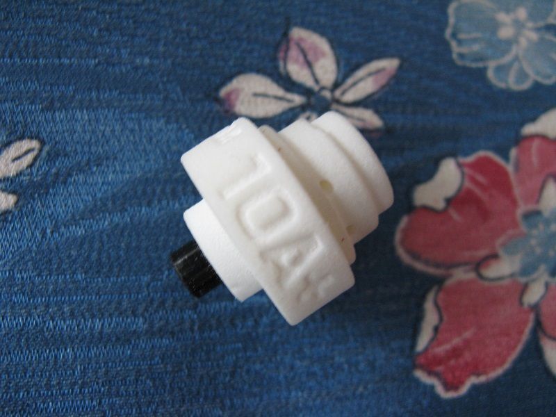
Again though the click mechanism works well and i'm confident enough to add the '+'to the '10A' text as current handling should be higher than the original Judco.
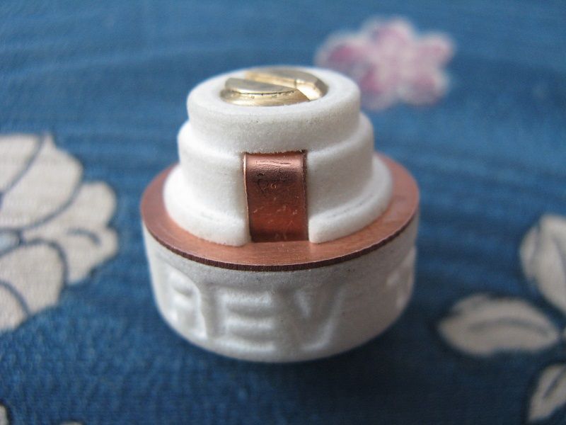
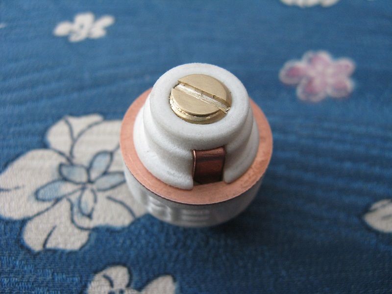
Now the two switch parts screw together giving improved access to the switches internals. The two holes in the top section are to hold the central plunger in a fully raised position so as not to disrupt the placement of the leads during installation.
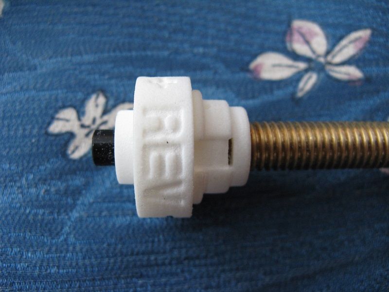
Instead of a spring i'm using a threaded brass rod that screws into the top of the switch. The length of the rod can be adjusted to ensure the correct level of compression to the spring on the drop-in module.
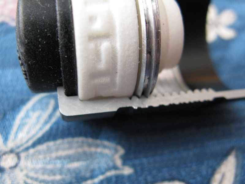
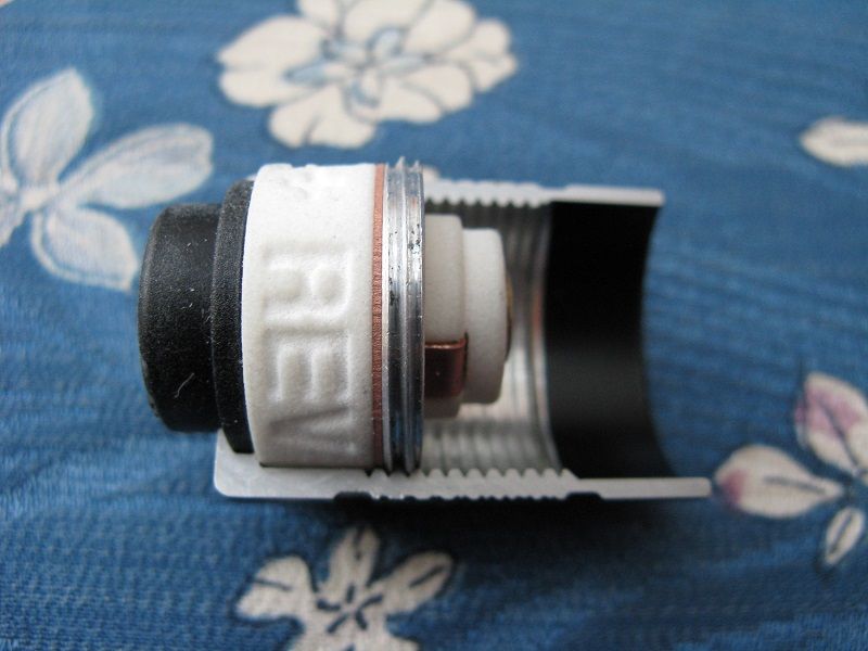
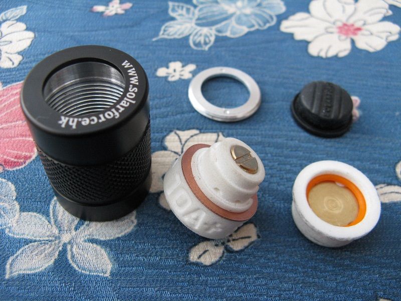
The switch shown resting on the shoulder in the bottom of a Solarforce S1 tailcap so as not to over-compress the rubber boot and potentially cut it. This is very important for the QTC application i have planned for the switch.
Hopefully i should have an even more positive update to post in a couple of days, showing the switch operating correctly.
Mark II will hopefully be the smaller McClicky sized version, a more universal format.
Update:
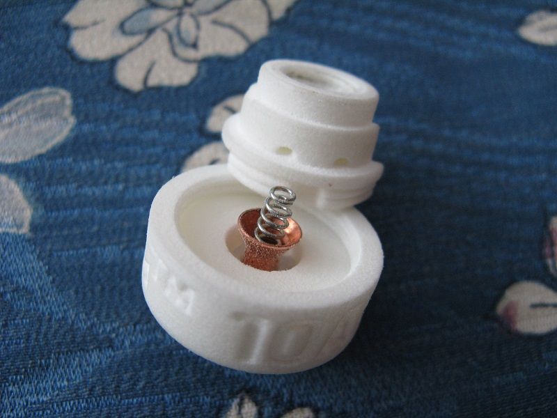
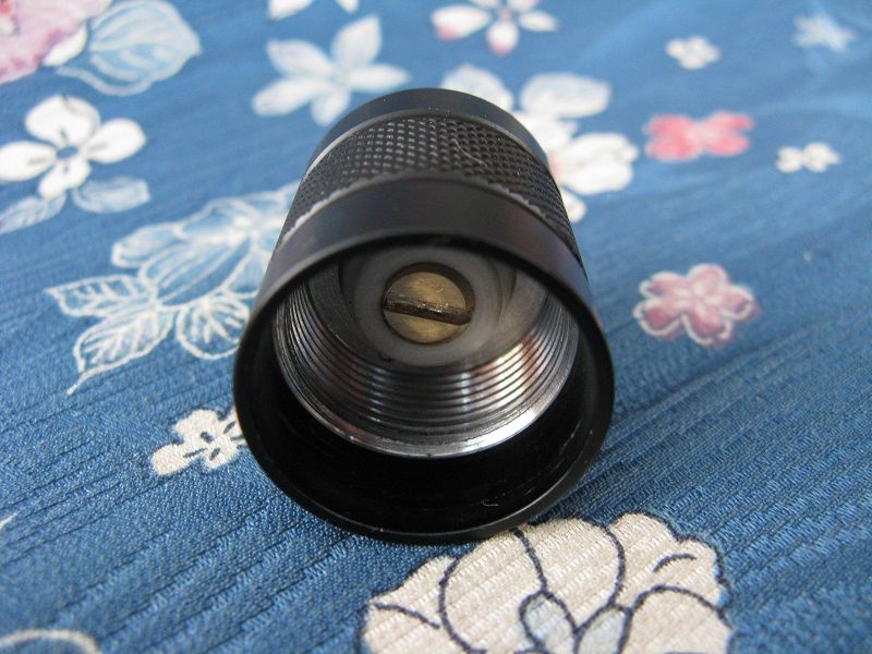
Funnily enough just after i finished typing out the last update i found the leads had already been delivered. I set about fully assembling the switch and just bent the leads into shape with pliers, which seemed to work well enough, but most importantly the switch works exactly as it should.
The brass central contact post shown in the pictures is shorter than it would be for usual direct battery contact by about 3mm, this is because i've sized it for use with my QTC puck, which allows variable electrical resistance and therefore output under different levels of compression. These QTC pucks will be making an appearance soon enough but for now i'm mainly focusing on the switches themselves.
In the next few days i'll work out how best to sort out the beta test list for the first 10 switches (probably by contacting those who have already posted in this thread) and when that's all done and feedback has been collected and assessed i will start a proper sales thread.
Thanks guys,i can't pretend this was easy but it went a lot smoother than i expected it to, i suspected the bottom part of the latch mechanism couldn't be printed but it turned out to be really quite impressive.
Thanks Scott, The QTC material in the little puck shaped thing, shown in the picture above, is simply compressed by twisting the tailcap. The clicky switch operates separately so the light can be turned off while the QTC is still compressed, allowing instant return to an earlier output level rather than trying to find it all over again like most other QTC systems.
Whoa! Wait a minute! You mean the light can be direct drive, no driver, and still be controlled through the tail cap with a Qtc pill in the switch you’ve built? Tighten for brightness desired then use clicky to turn off if so desired? Or leave clicky on, tighten for on off level control? Oh man, this is gonna be nice! Dial your level, enjoy. click, off. Click, back to the previously scheduled program!
Rich! The ultimate tailcap. Can hardly wait to see how this works in hand.
Tofty, with the QTC in the switch- would a driver be needed, or can this be used to direct drive and adjust output by turning the tailcap? I keep reading this thread over and over… it just sounds too good to be true. I’m really looking forward to you getting full production going. My wife wishes you hadn’t done this- I guess 10amps and QTC are only fascinating to some of us.
I really really really like the qtc potential here. you don’t fancy giving us a shot at beta testing that do you? I already have an mtg2 host in mind for that one.
cant wait as I’ve been itching to have a play with qtc since I first read about it.
Thanks Dale that was a better description than i gave, yep it should work exactly as you say. The one major thing i don't like about other QTC lights is they operate just like the Mini-Maglite which for an interface is crap. I can deal with twistys as it's just on and off but the maglite had to be twisted to turn on then focused to find the best focus.....every time. Same with the QTC lights twist on then twist some more, then a bit less and just a tad more for the preferred output. I like to think my solution cures this problem somewhat.
Direct drive or single mode driver are preferable (modes just make it far too confusing). I've been running my first generation QTC system with a Malkoff M61 and it seems to work fine. The one thing i'm not sure of is the resistance of the QTC under full compression and what reduction in output is seen when on full. The puck can be tailored for this though with different amounts of QTC material able to be installed into the puck to give balance between sensitivity and resistance.
You're obviously not mentioning it enough, she'll come around to it eventually.
I have been looking over a few of my tail caps lately. I noticed that the Malkoff tailcaps are similar to the Solarforce tail caps in length and circumference. Have you tried the switch in any Malkoff tail caps yet?