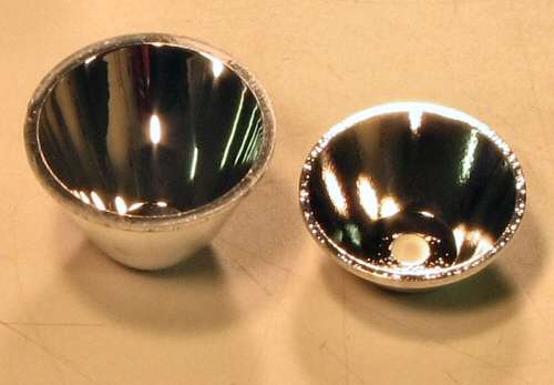
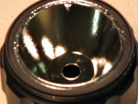
I got a couple hours to work on this today, so here is the info and pics. I decided to start with the reflector. The original plastic one was 46mm Dia. and I had ordered a smaller diameter one, not knowing the size.
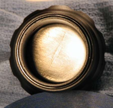
I will make do. I have to make a ring that will fit tight around the new reflector, so that it fits in the head. I first thought about using the old reflector, but it's too brittle to work with. I finally decided on a cap off a spray can. It's Polyethylene and it's easier to work with. I cut the center out with an exacto knife and used emery cloth to get it to the final inner diameter. I made it so it would snap over the edge of the reflector like this.
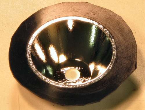
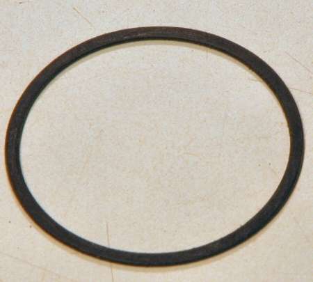
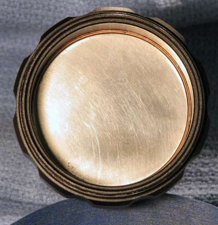
Now I have to get the 46mm OD, so I used a pair of scissors and then the emery cloth to shape the OD. Here's the final ring, ready to go.
Now I put it all together and see how it works.
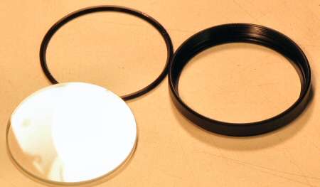
I also decided to do the lens too. I removed the lens (camera filter) from the housing by unscrewing the locking ring and lifting the lens out.
and here is the finished head with all the components in it.

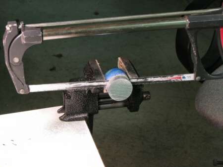
Since I still had a little time, I decided to tackle the heat sink. The stock one is tiny and I am replacing it. I used a shallow reflector to give me some more room for a heat sink. Now I have to cut it. It's 1-5/8" Aluminum rod stock and I sure don't want to do this again. I need a young guy to "assist".
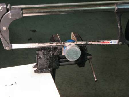
I'm already tired!
10 minutes later... Seroiusly?? I'm so glad it's not steel!
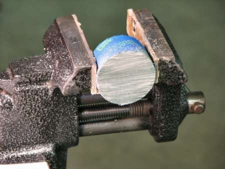
About 20 minutes with breaks to slow the heart rate down and to breathe.
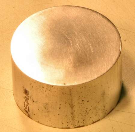
I still have to cut the step in it, but not today! I need to go rest...
More coming later...
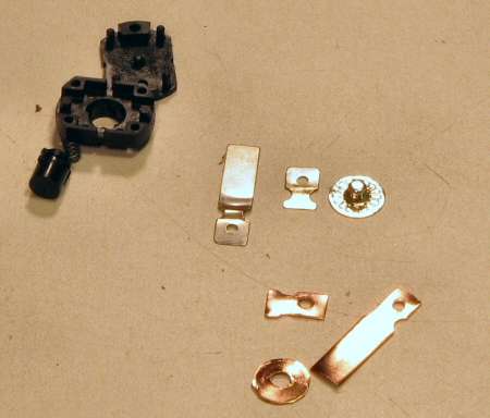
After a little rest, I did the tailcap mod this morning. The stock clicky switch is rated at 1amp @ 250VAC, which means 2amp @ 125VAC and "DC rule of thumb" says it would be 2amp at 12vdc. Well I will be at 3amp @ 3vdc, so it might not work.
Once I opened up the switch and saw the parts, I would say it would take 3amp with no problem, especially in a light like this with a short run time.
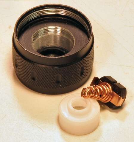
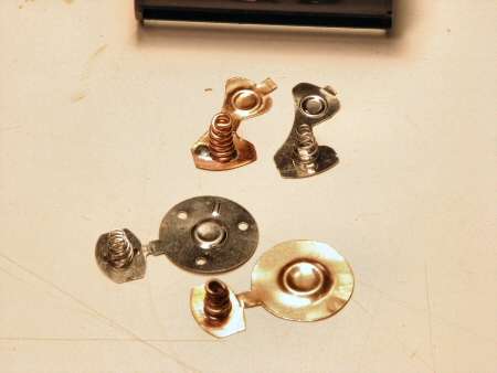
But... I have it apart now, so I might as well put copper parts back in . The photo shows the stock parts and the copper replacements.
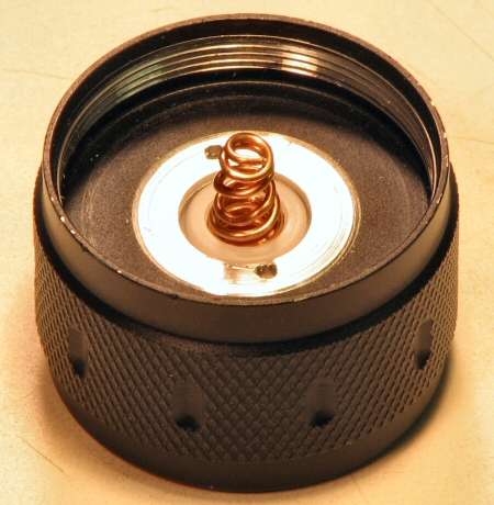
Here's the switch put back together with the copper replacement spring I made.
and here's the finished tailcap.
We are going to have a "Cold Snap" here in TX, temps below freezing for the next few days. (So the weather people say)
 . If that happens, I probably will not finish the build till it warms up. Garages in TX aren't insulated!
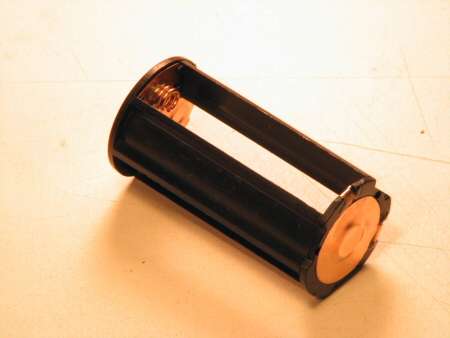
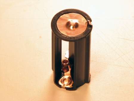
As the cold front comes in I decided to get the battery holder "copperized". I just took out the stock metal parts and copied them in copper, springs included.
and here is the finished holder.
Have Fun, I'll be back sooner or later...
Heat Sink Time!
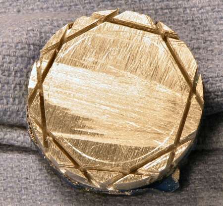
As you have seen already, heatsinks will kill me sooner or later. Now that this one has been chopped off to length, I have to put a step in it, so that it clears the inner body ID.
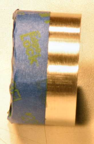
I have scribed the ID on the heatsink and I have taped off how far down I need to go.
At first I was foolish enough to think I could use a file. - Wrong! I had to break out the Hacksaw  again. Oh man, I was hoping I wouldn't have to do this!
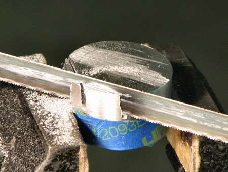
I ended up making 8 cuts around the center ring
and then I cut around the side till the pieces all came off.
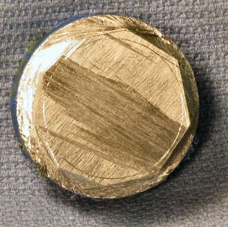
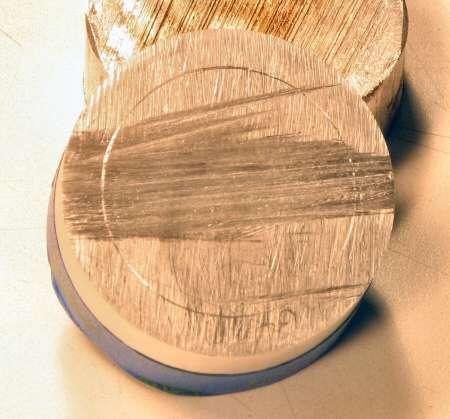
Now I can do pretty good by eye, when shaping something into a round, but I cheated here and I will show you.
Using magic marker helps a lot when taking material off. You can see what you have removed and need to still remove. I did this more than once as I rounded the heatsink.
Here is the final shape
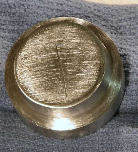
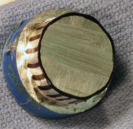
and a couple shots of the heatsink in place.
This is at the battery end and it does not touch inside, because I need to be able to take the body off once in a while.
Here's the business end and I have used a copper shim around the heatsink to make the fit tight. It's tight enough that I have to tap it in with a hammer.
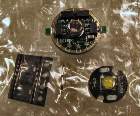
Next time is making the cavity fot the board and attaching the emitter.
Another day, Another Video
The video shows putting the T6 emitter on, wiring it and checking to get proper reflector height for a good beam.
Tomorrow is painting day.
Ok, I have painted and clearcoated the light. I have a photo of the finished light and I will describe the paint I used.
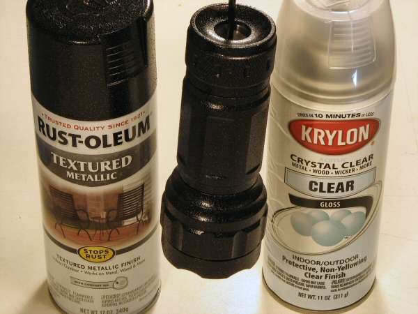
The paint is Rustoleum Textured Metallic paint and it has Copper flecks in it. It leaves the finish textured and the black with copper in it is fantastic looking!
The Clear is Krylon Crystal Clear. It's the best clearcoat paint I have ever used. I use it for doing an OP finish on reflectors and as a top coat on just about everything, from flashlights to knife scales. It's a great paint.
Here's a closeup of the finish.
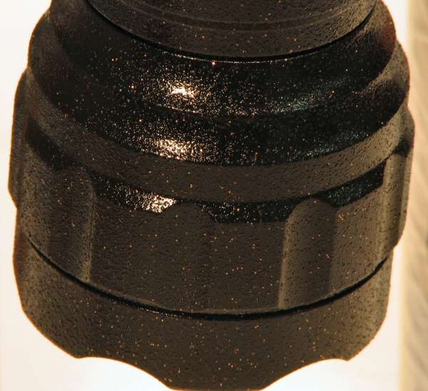
The photo does not do it justice. The light feels good in the hands now, like you could never drop it and the copper in it just looks great!
Hopefully this week-end I can do the final assembly and beam shots.