It’s press fit on mine. Push on the button boot… hard.
Thanks relic for the info. Did you ever get around to changing the sense resistor?
.
I got this one on the way to try out in the defiant with XML-2. Looking for different options with a buck driver.
I do not recall, but if I didn’t update the mod thread, probably not. I just checked the tailcap current at 8V and I get 1.4A (11W). That tells me it’s still right around the specified 2.8A to the emitter.
It’s on my to-do list to upgrade the emitter and driver output.
That lck-led driver looks nice. At 5A, you’ll want a nice copper mattress for the emitter to sleep on. ![]()
Hi,
Thanks, that did it, but you weren’t kidding about the “hard” part :(… my thumb is still a little sore :)….
I found this display in a local HD (Bradford):

I’m curious as to how well they’ll sell in Toronto.
They aren’t moving many in here in Maine HDs.
Hi,
I am planning/hoping to direct-drive one of my DSTs, with a (rather large) power resistor inside the DST pill in series with the + or - side, so I pulled off the press-fit contact board, but it looks like there’s an IC plus some resistors on that board. Can anyone tell me what those are. Also, I’d prefer to have a “clean” contact board, so would it work if I just remove that IC?
I removed all of the components to use it as a contact board. You can do that and add the resistor for a very simple current limiter.
relic,
Thanks!
I currently have some 1 ohm/3w resistors, but they barely just fit into the DST pill, so I’m awaiting some (hopefully) smaller ones. I’m looking to put an MT-G2 emitter on a Noctigon, with 2x16340 batteries, so I think that I’ll need to drop about 1.8 volts across the resistor, so:
- 1 ohm => 1.8 amps / 3.24W
0.5 ohm => 3.9 amps / 7.02W
0.65 ohm => 2.7 amps / 4.86W
The MT-G2 is spec’ed with forward current of 3 amps, max, so is it correct that the 1 ohm would be under-driving it and the 0.5 ohm would be over-driving it?
Also, in your all’s experience (bad grammar, sorry) what’s the best way, mechanically, to actually install the resistor?
- Solder one end of resistor to + or - contact on contact board, and solder a wire to the emitter on the other end of resistor?
- Solder wires to each end of resistor?
While I’m ok with understanding the concepts, I seem to be a kind of klutz when it comes to actually “building” anything, so simplest is best for me…
that lck led 5a driver is the one I used for my mt-g2 build, its a really nice driver with good mode spread. It’s certainly the one I’ll be trying to fit on any other 5a build.
Gords,
Maybe I’m being stubborn, but I really want to try the DD first. I may switch to a driver like the above later, but I want to try the DD first.
So, still looking for recos re. best/simplest way to add the resistor in-line inside the pill.
Also, I would still like to know why they had components on the stock driver? What do those do? Is the stock driver current regulated or something?
I’d go with the 0.5 Ohm or smaller, since there is resistance elsewhere in the light. With two 16340 cells, you might want to avoid the resistor, since they aren’t exactly going to deliver tons of current.
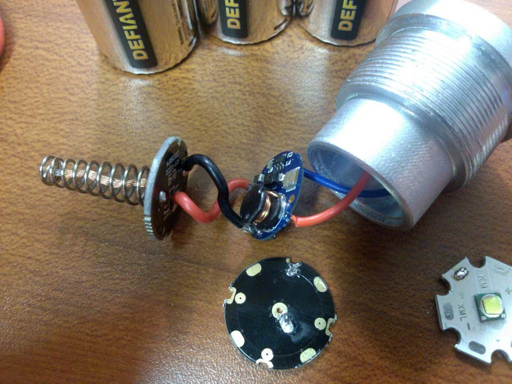
If you decide on the resistor, you can solder one end onto wherever positive comes through the board. Here’s a pic from my mod, bad angle but you can see it’s somewhere in the middle.
relic,
Thanks! I forgot that I wasn’t taking the other impedances into consideration… too much theory :(…
I’m still waiting for the 0.5 ohms to get here, and I guess that I feel “safer” with having some resistance that I purposely put in, esp. with the cost of the emitter :).
I’m not sure if I was clear about the two choices that I mentioned earlier, but for the 1st choice, what I meant was to solder one of the leads off of the resistor directly to the pad on the contact board, to minimize # of solder joints. But, having thought about it more, I’ll probably go with what you showed, soldering a wire to each resistor lead, because I’ve had occasion before where I pulled the pad off of a PCB, and I’d like to avoid that.
Thanks again, will post some pics when the parts get here, and IF I get it working :)…
Later,
Jim
I was thinking you could solder the resistor lead right on, but adding a wire will give a little more flexibility. I think the pad will be fine either way.
Definitely safer to start with some resistance there, and once you find out if it sucks you can remove it ![]()
i ended up selling mine to mrsdnf
garry cursed me with this light though as i now have a 5.7amp xml2 one coming from OL
i tried to get rid of it but it came back!
Thanks. FYI, I’ve already tested an MT-G2 emitter with the 1 ohm resistor, direct to 2x18350 IMRs, i.e., so no additional resistance, and it was fine, at least for the brief time I tried. I measured 1.78 amps with that setup.
I’ll do the same test with the 0.5 ohm resistor when it gets here, and also 2x1.3 ohms in parallel (to get the 0.65 ohms).
Later,
Jim
Yes I do have jmpaul’s light. I’ll finish it when I’m able bodied again. Soon I hope. I thank you again for the light. I’m excited about what it’s evolved into so far and if it was not for members like you I would miss out. You’ll love your new ‘’Old’’ Lumens light coming to you.
im glad it ended up in a good home… i broke the 5 amp driver i was going to put into it and just had it sitting in a foam case until i worked up my confidence again lol
I foolishly ordered a 17mm driver for my defiant…what I did was use a p60 brass piece…then just grinded down the threads until it press fit easily but securely…now I have a 3 mode defiant which reads 2.5a or so with 3C alkalines…may get ni MH to get a little more current but so far it’s great!

Hi,
Nice! It’s kind of hard (for me) to see, but did you solder the original DST spring onto the spring of your driver board? Is that what you did?