What did you mod today?

I changed the lens in 2 Convoys this evening.

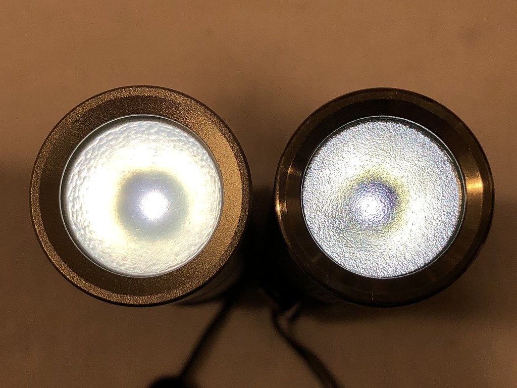
First was my S3. It has a CREE XM-L2 4250-4500K LED and an AR lens. The beam was not the best with lots of artifacts and a greenish ring. I didn’t use it much, except for outside. I tried switching to a non-AR lens and a different reflector, but the beam was not much better. Then I decided to make a diffused lens from some acrylic spacers that I kept from a storage container:
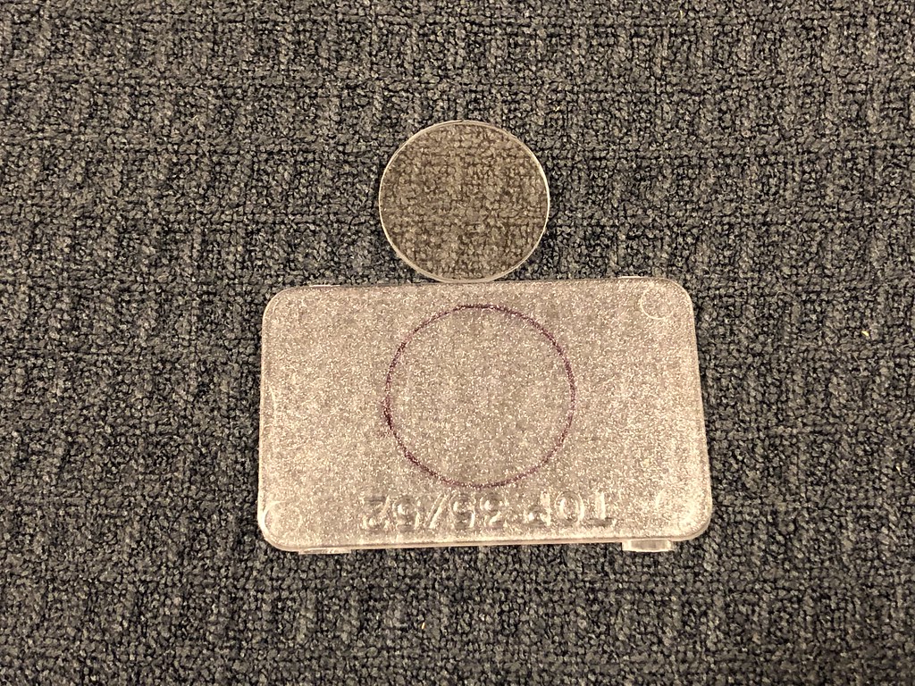
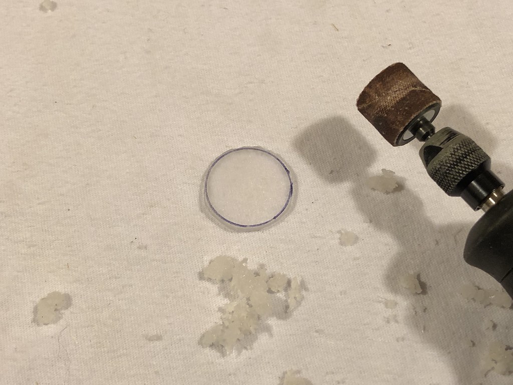
What a huge difference that made! No artifacts and I even see some rosiness now.

Second was my S2+ clear (silver) with a Samsung LH351D 4000K 90+ CRI LED. I’ve worked on it before to clean up the beam with a different reflector, but it still had some artifacts. So I replaced the non-AR lens with the same acrylic lens and it made a big improvement, but made the beam too diffused. So I took the AR lens from the S3 and sanded one side with 60 grit sandpaper. That turned out to be perfect - no artifacts, but still had some throw.

Left S2+, right S3:
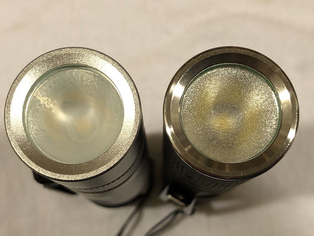
Sure I know I’ve lost some lumens doing to this, but it’s worth it to me to have great beams! And after all, these are EDCs, so the emphasis on beams is more important than lumens.

I made a PD charger deliver 5vdc through a c-to-c cable to a device previously only able to be charged a-to-c. I know what you’re thinking. You wish you could solder like me!

Nice job :+1:

I really wish manufacturers just did it right to begin with. Seriously… it’s two resistors. Is that too much to ask?

Spooky…

Yeah so I started here and dropped two 5.1k ohm resistors to ground and got 5vdc at the vbus just to test the theory. Other resistor is on the reverse. So a resistor from each cc pin to ground does release 5vdc from the PD charger. Check.

Then I got out my exacto and cut up this:

Now question for you… you can see that the two cc pins are actually attached here to vbus. I cut them off vbus, isolated them and then grounded them through the resistors. So questions: A) why were they tied into vbus to begin with? And B) does my design do something dangerous? I went through a charge cycle and it seems to work. And……

YES it seems to be that simple or close to it.

(The lit led here is from a type-a charger)

Can’t answer your questions Prplxt, it is not my expertise I’m afraid.

Not today but yesterday I checked the 5700K 90CRI Samsung LH351D leds that I got from Kaidomain in a Nightseeker NSX3. The reflector holes in this flashlight are an unusual 7.5mm and Nightseeker did not bother with fitting centerpieces, they used standard 7mm ones that do not center the leds very well. But with the big die of the LH351D this is not problematic for the beam.

I did not like the stock user interface (always starting on a blinding turbo :confounded: )so I replaced the driver with a good old BLF-A6 driver (from Banggood) soldered into a 17mm->22mm brass adapter (from the Convoy store).

As you may notice in the picture, I did the voltage-spike fix suggested by DEL, even though this driver (unlike the related X5/X6 driver) does not suffer from the drop out of turbo problem.

Even though I did the usual resistance reduction measures, spring bypasses and shortened led wires, the current draw and output on the maximum setting (that is basically direct drive) were a bit less than hoped: 12.5A and 2900 lumen, there was not much difference between a 40T and 30T battery. Apparently the voltage of this led is relatively high.
But I’m happy with the 2900 high CRI lumen in this mod, makes for a pretty nice flashlight.

The beam is nice, a floody hotspot that gradually dims into the spill without obvious tint changes (the reflectors are light OP).

The tint is an attractive cool white, close enough to the BBL, also at low current, and colour reproduction is as expected very good. In the hotspot at 350mA: CRI=92.7,R9=55,CCT=5330,duv=+0.0031, at max 12.5A: CRI=90.6,R9=45,CCT=5750,duv=+0.0040. The lime-coloured AR-coating on the front glass may have had an influence on the tint.

Some really nice mods and info being posted up. Thanks guys. Not doing a lot myself but always interesting to see what others are up to.

Got bored today and decided to freshen up an old Energizer headlamp with a 219C 4000K from Mountain Electronics.

Wow, that thing actually had an LED on a star? Color me impressed.

Nice soldering job djozz!

Yeah same, I took it apart out of curiosity and figured I might as well swap it since it was on a star. Now I just need some high CRI 5mm’s to complete the light :smiley:

Here ya go

Very nice ” djozz ” I really like the BLF D80V2 you modded. :+1:
Thank you for the detailed explanation. I would love to copy your mod one day. :smiley:

I’ve had my eye on that thread but haven’t really had a reason to order any. Guess I do now!

I am currently putting BluswordM’s 3rd Gen springs in everything I can. Helps me with soldering skills also. Hot Air station is getting a workout also.

Thanks, I’ve done this particular “tombstone” job many times and became handy with it :slight_smile:

djozz, may I ask what purpose the “tombstone” serves on an A6 driver?

It isn’t necessary there as the Attiny13 doesn’t have the glitch we see on the X6 Bistro driver with Attiny25. I have always used the A6 driver for high powered lights, built from scratch of course with top components, and have run lights over 30A on the A6 driver many times with no issues. The A6 driver has been my go-to glitch free set-up for years. I’ve seen copper traces vaporize off contact boards running this driver, sheer output power more than a thin trace could carry.

So yeah, I’m wondering what purpose is served doing the Bistro mod to an A6. ( have built several hundred of these drivers with excellent result, wondering what I’m missing)

You are not missing anything, and your description of the BLF-A6 driver proves that. There are two very insignificant reasons that I did the fix that is not fixing anything:

*DEL once remarked that he was surprised that the Atiny13 worked at all with the voltage spikes it receives in the standard FET driver. So my thought is: it can’t hurt to reduce those spikes

*I enjoy doing the little solder trick

The low pass filter cant hurt anything it’s a good measure to increase stability even if not needed
who knows if the chip may get long time damage from those spikes

Ah, ok, I see. I’ve been using a pair of 200 Ohm resistors for a 100 Ohm value… didn’t have the 100’s but had a tape of 200’s for Zener mods. I’ve also used 1206 100’s sideways out of a notebook of resistors, tricky and challenging getting those to clear. Lol

I quit doing the lean together thing, simply stand the three up then bridge with solder. :wink: