What did you mod today?

They’re well worth it, even in plastics or normal steel and soft metals. If you ever get the whim, check out Edge of Arlington (eoasaw.com I think)….they’re a distributor and if they don’t have it on the site they’ll order it quickly at no extra charge. They seem to have the best prices on most items (for what you can find online). I got a set of the acrylic 60° bits from them after considering it for…years and years…and they were great to deal with. I can usually get better prices from a local supplier so it might pay to makes some calls if you have anyone reasonably nearby. Like I just picked up a set of screw machine length bits for about half through this supplier vs. what I was seeing anywhere online.

Those Vortex bits are pretty awesome. I’ve talked to two shops (auto body and sheet fab) and they both said they love them and haven’t torn them up yet. One is using them only in 18v drills so they’re getting some abuse, but looking at a few of the worn/used ones they looked really good. Interesting grind on them. I doubt I’ll buy any for myself but I can see these being fantastic for sheet and thin plate - better than pilot point types like the box store brands have been pushing for awhile (those have their place, though). I’m curious who invented that Vortex step tip design…probably not Norseman but maybe. They’re still plugging along at their factory but I was sad to learn that some years back they had to start sourcing their M7 steel from China…still cut, ground, and finished here, though. Comparing to some older ones I got in the 90s, these new china-steel ones seem to be every bit as good, so that’s a relief. The devastation of the North American steel industry is just incredible, affected so many things. I’m not sure where the other US bit makers get their steel but most of them seem to only do M2 or M3 standard stuff. The M7 moly has always been kind of exclusive to CTD I think, and it’s not sooooo much better, but for hand work it does excel. In a press, not a big deal really, and not better than cobalt for where cobalt shines.

Nice work, Don! ….can you fix the bezel with a helicoil? :slight_smile:

There are enough threads on both pieces that it tightens up okay. The light is probably 1.5 to 2 mm shorter now. Helicoil would be impractical given the dimensions (thickness-thinness) of the materials.

Where the threads were cut for the bezel to thread on the head material seems to be slimmer than some other lights. That threaded area on the T2 measures 0.5mm to 0.8mm thinner than the same spot on an Emisar and a Sofirn light I had handy. That thin section fractured when I rapped the head with bezel removed. Assembled it is probably just fine. Thrunite doesn’t want anyone taking their lights apart for any reason.

I was kidding…not sure they even make helicoils that large even if the thread could be matched. :slight_smile: That’s pretty…impressive?…that the threads split like that so readily. It’s possible that - assembled - it could still break like that although with more metal supporting the load (plus the absorption of the loctite) it might not. But you showed the light who’s boss!

Often I take what I read as completely serious. :person_facepalming: That has embarrassed me before.
:beer:

:beer:

Just a small mod - I added a lighted switch to my copper T3. I decided not to use the clear rubber boot that came with it since it blocked more light than the ones I got from KD. Which meant I needed to lengthen the switch button like I did with my T2 mod.

I had a hard time removing the switch retaining ring until I realized it loosens counter clockwise (like it should) as opposed to the S2/S2+/S3/S8/C8 etc.

I was planning on slicing the 3000K 519A dome down to 1mm to bring it to 2600K, but it was already nice and rosy so I left it as is.

I repositioned the Omten switch since it was not centered and increased the resistance to 15K since it was way too bright stock. I made a clear washer from a plastic container that I cut out with a Dremel. The green lighted switch draws 0.11mA at 4.1v, so 1.1+ years on the 14500 battery.

1 Thank

Very simple mods. The lamp has a dedomed 519 2700k and the Swiss light has a dedomed 519 3500k. Just some good, clean fun.

The little Star Tracky one with the red/green buttons is the “Swiss light”?

Kewl… never saw nor heard of that one before. Cute! :laughing:

^ What he said!

That Swiss light looks great! Assuming this was an old incandescent bulb originally, how did you get a thermal path with the LED?

Indeed! I just mounted a 16mm mcpcb on top of the existing threaded bulb mount. Then I wired it to a 2AA pack. I had to remove the existing reflector so things would fit (or maybe I was too lazy for further modifications…) so I added some DC Fix to the lens for an improved yet still poor beam.

It has a really nice red tint between the red film and the warm 519 emitter. I keep it next to the bed in the momentary switch mode for late night snack trips.

Fireflies E07 2020 Upgrade… 2021 driver, new switch with cool leds and transparent rubber switch, Anduril 2
Cheers :beer:


Designed and built an 18650 to 2x D Cell adapter with a field swappable 18650, integrated charging and protection for my Maglite.

Pics here: 18650 to 2x D cell adapter with TP4056 Charging - Album on Imgur

If anyone wants to print their own, it’s available here: https://www.tinkercad.com/things/lSpcdjz28YZ on TinkerCAD

Fits the common TP4056 charging module you can get for under $1 almost anywhere.

IMPORTANT NOTE:
The higher voltage will burn out a regular 2-Cell incandescent bulb. You need to update your flashlight bulb to something that can accept the higher voltage. Anything that is designed to work with 3 cell (C or D battery) flashlights will likely be fine or an LED module like LITT or Nitecore have built-in regulation to accept a wide voltage range.

ASSEMBLY:
Parts: 3D printer (or access to use one). Brass washer, Brass screw, TP4056 charger, some wire (20-22 AWG), battery contacts, super glue, and be able to do some very simple soldering.

3D Print the adapter linked above

Measure needed lengths of wire and cut to size. There are holes through the print to feed wires to each end of the battery chamber and to each end of the adapter overall.

Solder the wires onto the battery contacts. (I went to the dollar store and bought a toy that took AA batteries to steal from instead of ordering a large quantity online.).

Feed the wires from the contacts into the appropriate holes, apply super glue to the back of them, and then insert an 18650 to hold them in place while it dries. (Beware some glue may get on your battery.)

Make sure the screw you use fits the positive hole in the print. This hole curves to meet the charging board so use a short screw, 1/2” or so. Solder a wire to the bottom of the screw. Feed that wire down the top of the adapter and then a little super glue to hold the screw in place.

Solder the negative wire to the brass washer. Super glue washer to the bottom of the adapter with the solder spot hidden under so it doesn’t get rubbed on and broken in use.

The 4 wire ends all meet at the back of the charging board, battery plus and minus, output plus and minus. Solder them all carefully to the correct pads on the TP4056. Then super glue the TP4056 into place with the USB port facing up toward the positive terminal but make sure it’s not sticking out past the top, you don’t want it to touch anything inside the flashlight while in use.

Dab a little superglue on the wires along the channel so they stay tucked in neatly and don’t get caught on anything.

Voila! You now have an 18650 adapter for your 2x D cell flashlight that has onboard recharging, low voltage protection, and you can hot-swap in a fresh 18650 when needed also!

If you are rougher and the 18650 seems to shake loose at all from its contacts, add a piece of sponge over the 18650 to support it. A piece of “magic eraser” type sponge from the dollar store works great for this.

Nice mod!

Nice Gd.ritter! Welcome to the forum. Yea, I need to get me a 3d printer. I have a few things I’d like to try.

Nice work, that’s a fiddly job! I forgot about those tiny pots on the board, such a nice feature.

Thank you! Yes tiny useful pots but the aux works strange and can’t use 2 levels but only one, blink and off. Maybe the old aux pcb don’t work well with new driver

It’s because the aux board is powered directly from battery and not the MCU. So LVP and resistors/pots, etc all present on the board to function independently of driver.

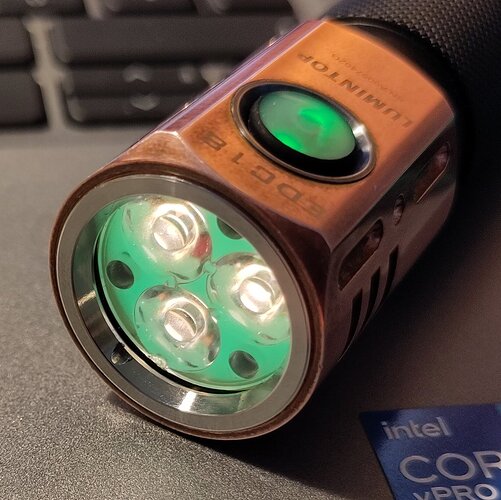
EDC18 copper, now with Nichia 519A 2700K :


2 Thanks