Yeah! That’s what BLF members do!
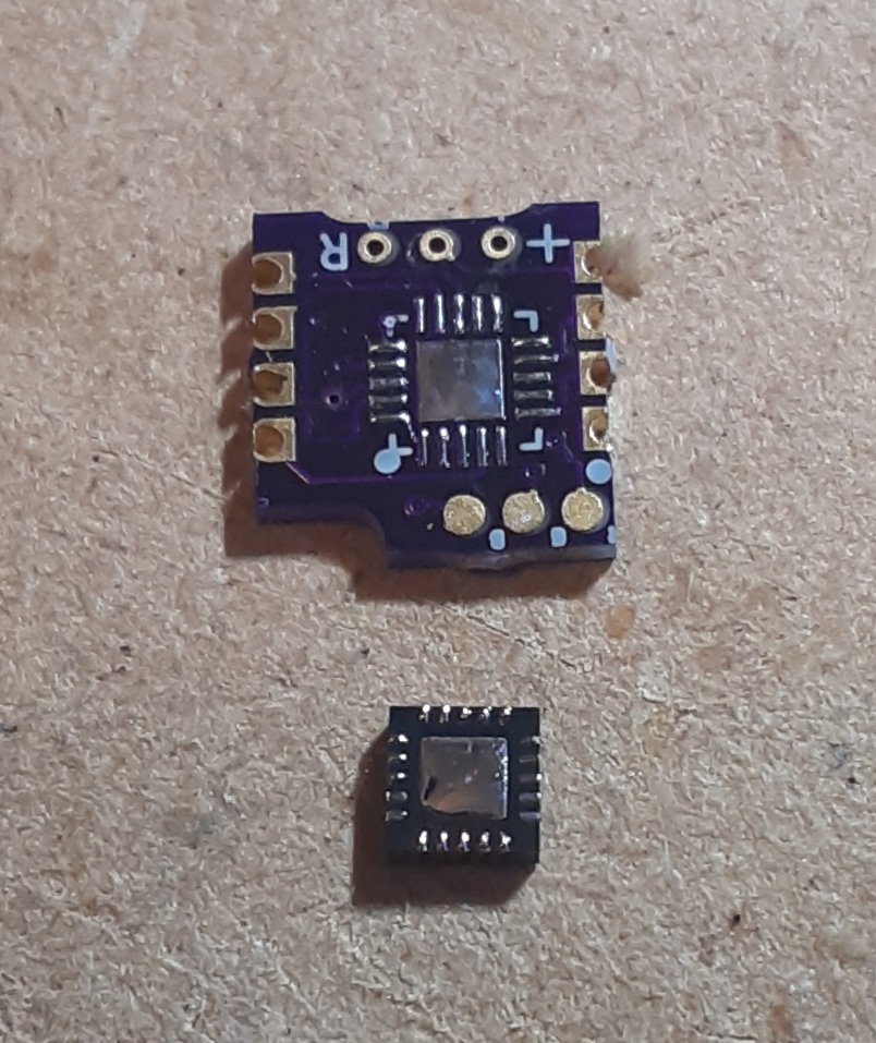
I ordered more or less one of every sfn/sfq/sf-whatever emitter kaidomain had, about a month ago, all as bare emitters. I’m in the process now of reflowing them all to various boards. Every single one Ive seen so far has that exact same notched corner on the one electrode, I still test it to make sure, and every single time thats been the cathode. So far it’s been true for all of them.
There’s a few on kaidomain now that weren’t there when I ordered a month ago. But ya, so far every one has been like this. So there ya go ![]()
And they’ll all been successful except that first one
2 Thanks
I just wish they had any kind of indicator on the top side
Flipping the emitter countless times made me annoyed yesterday ![]()
I can’t check my six leds because they are in the ec06 and I don’t make a picture😩
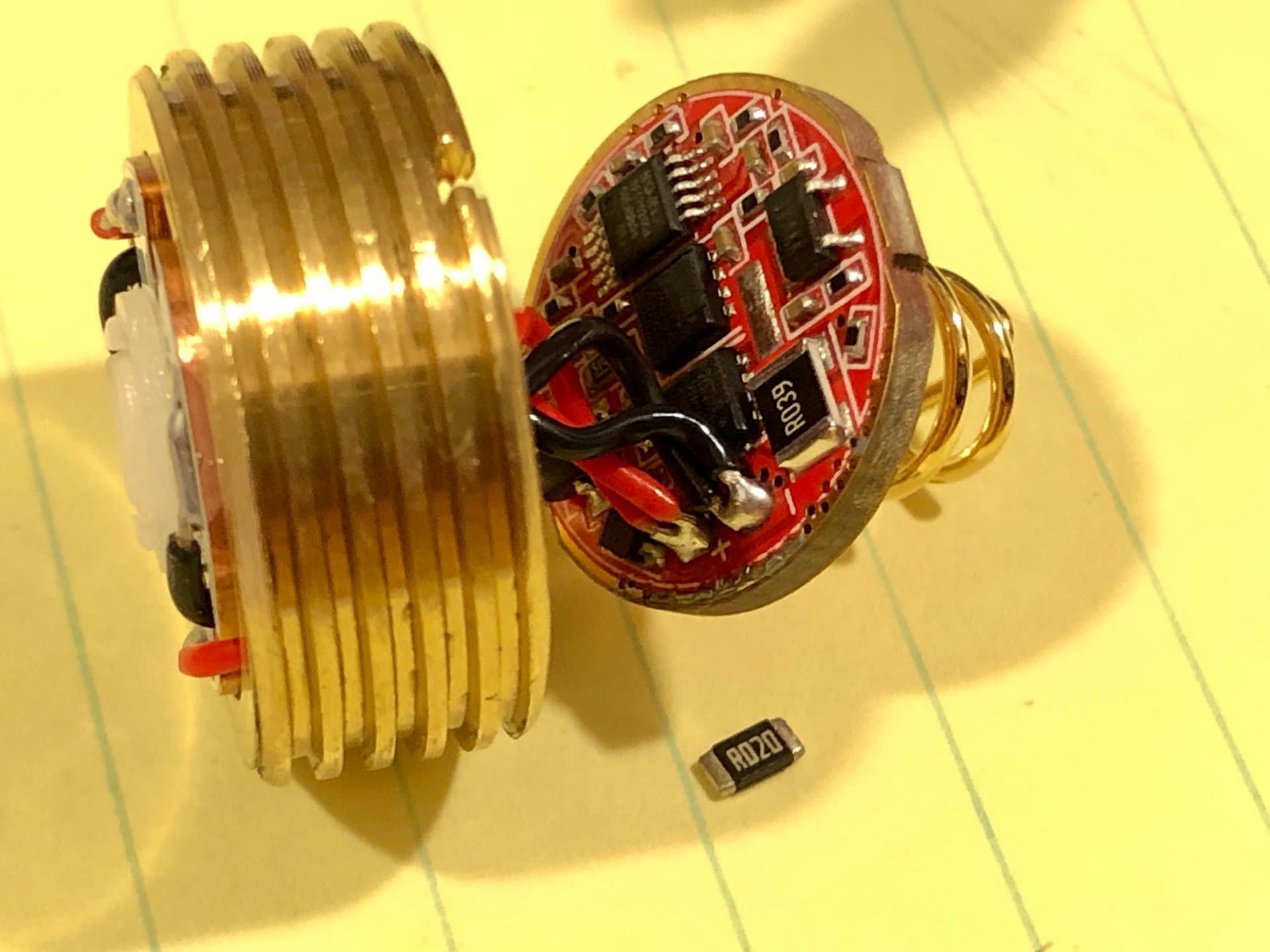
I replaced the sense resistors in all my Convoy “SST40” drivers that are used with my quad E17A flashlights. I was using a 50% max mode in order to keep the current to less than 4 amps, but didn’t like only having 4 modes vs 5. So I doubled the resistance in order to reduce the current by 50%.
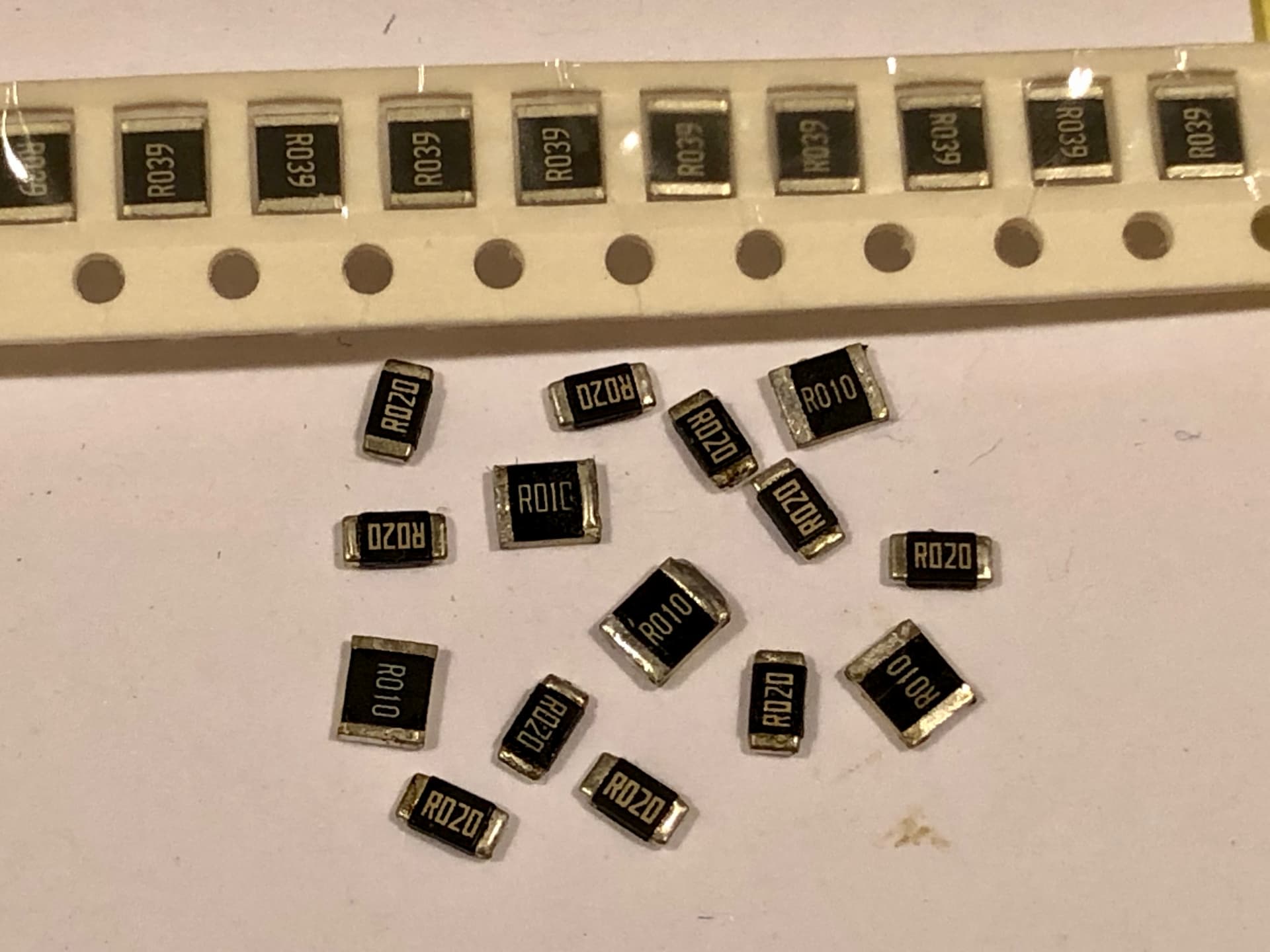
I got these 0.039 ohm resistors from AE: 50pcs 1210 SMD Resistor 1% 0.5W
Most of the sense resistors were R020 and I replaced them with R039, but some were R010 so I stacked 2 of the resistors (parallel) to make them 0.02 ohms.
Having the extra mode was definitely worth the effort!
2 Thanks
Newbie question time. All else being equal, what effect does this have on battery consumption?
A. Consumption is the same because current is converted to heat via added resistance.
B. Consumption is roughly halved due to less current draw.
C. A bit of both.
Do you really have 15 convoys with quad e17a? Wow
Anwer is B
I should’ve double checked my photo before posting it. ![]()
I actually have 12 quad E17A flashlights, from 1800K all the way up to 6500K. I only have the warm/cool white versions, none of the colored ones. They are quite special LEDs and mixing them to get the tint/CCT you want is pretty neat.
I was also modding some lower powered flashlights so those sense resistors got in the photo too.
Not so big difference)
I think I got your idea. Someone buys 1 flashlight with tint ramping but because in the s2+ it’s quite difficult to do tint ramping, then you have to have a set of ready-made s2+ with a temperature step of 400k.
It’s good that you didn’t need a set of temperatures in 100k or 50k step)
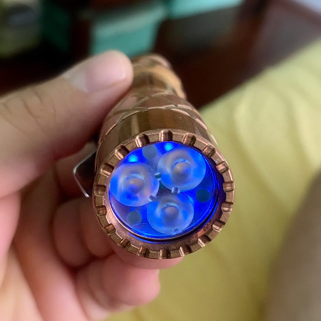
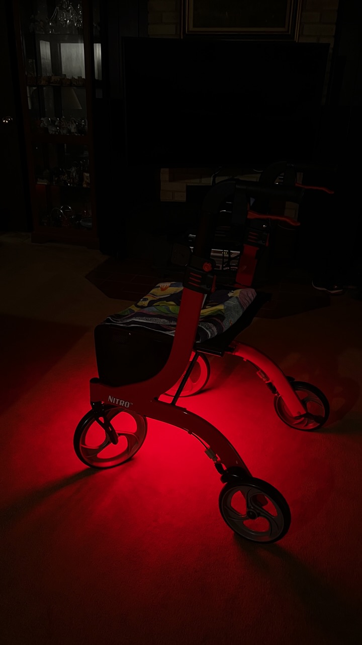
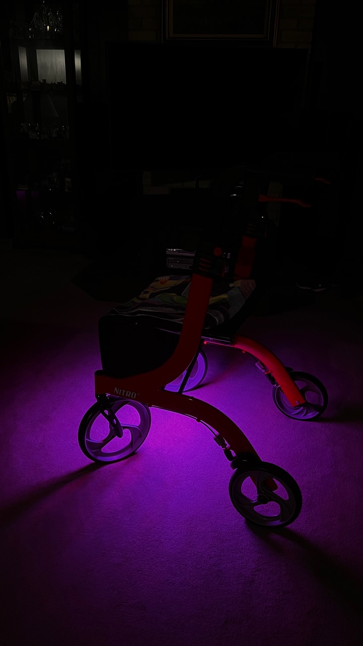
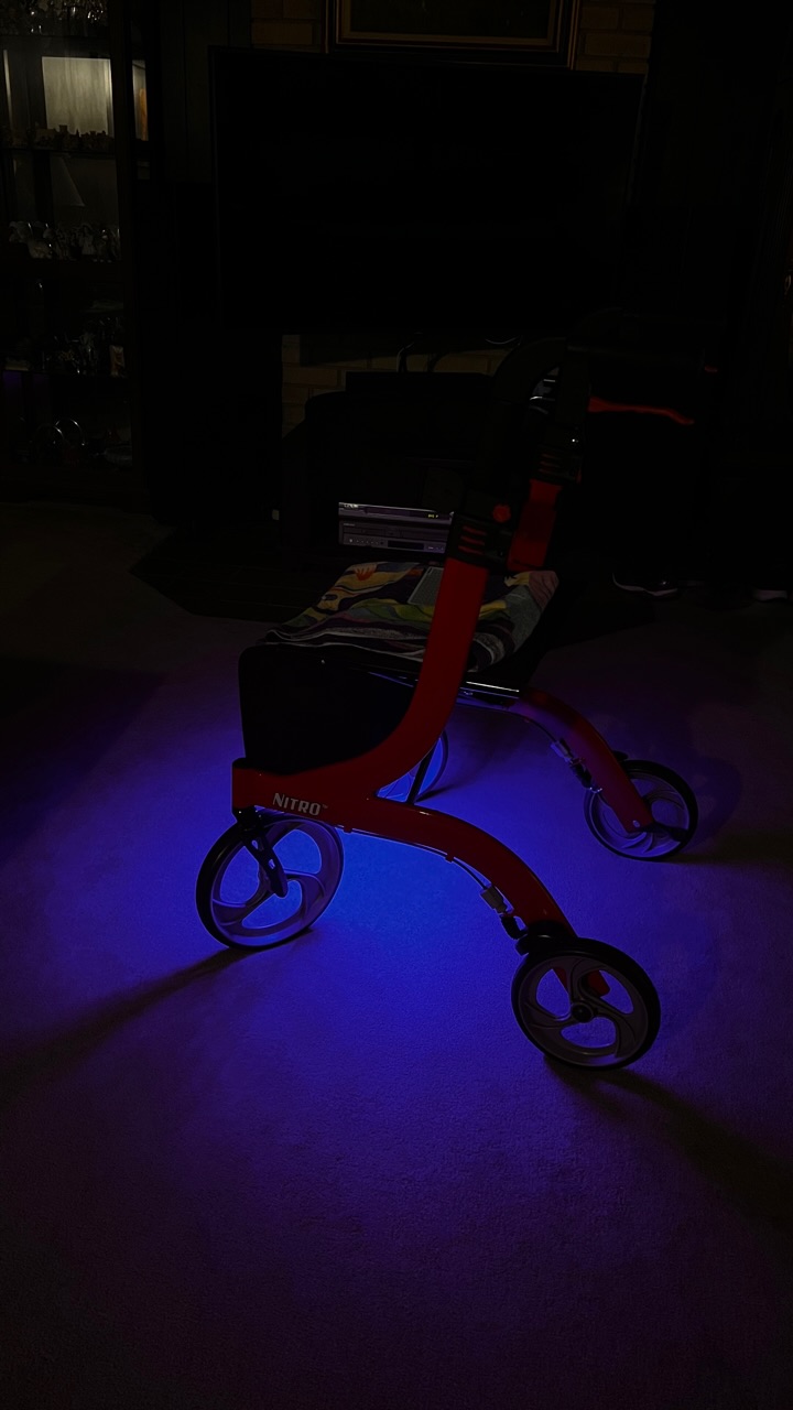
I added a separate bank of 72 blue emitters under my Nitro (rollator) so I can now choose between that lush red glow and a vivid blue glow, or use both for a bright purple effect!
3 Thanks
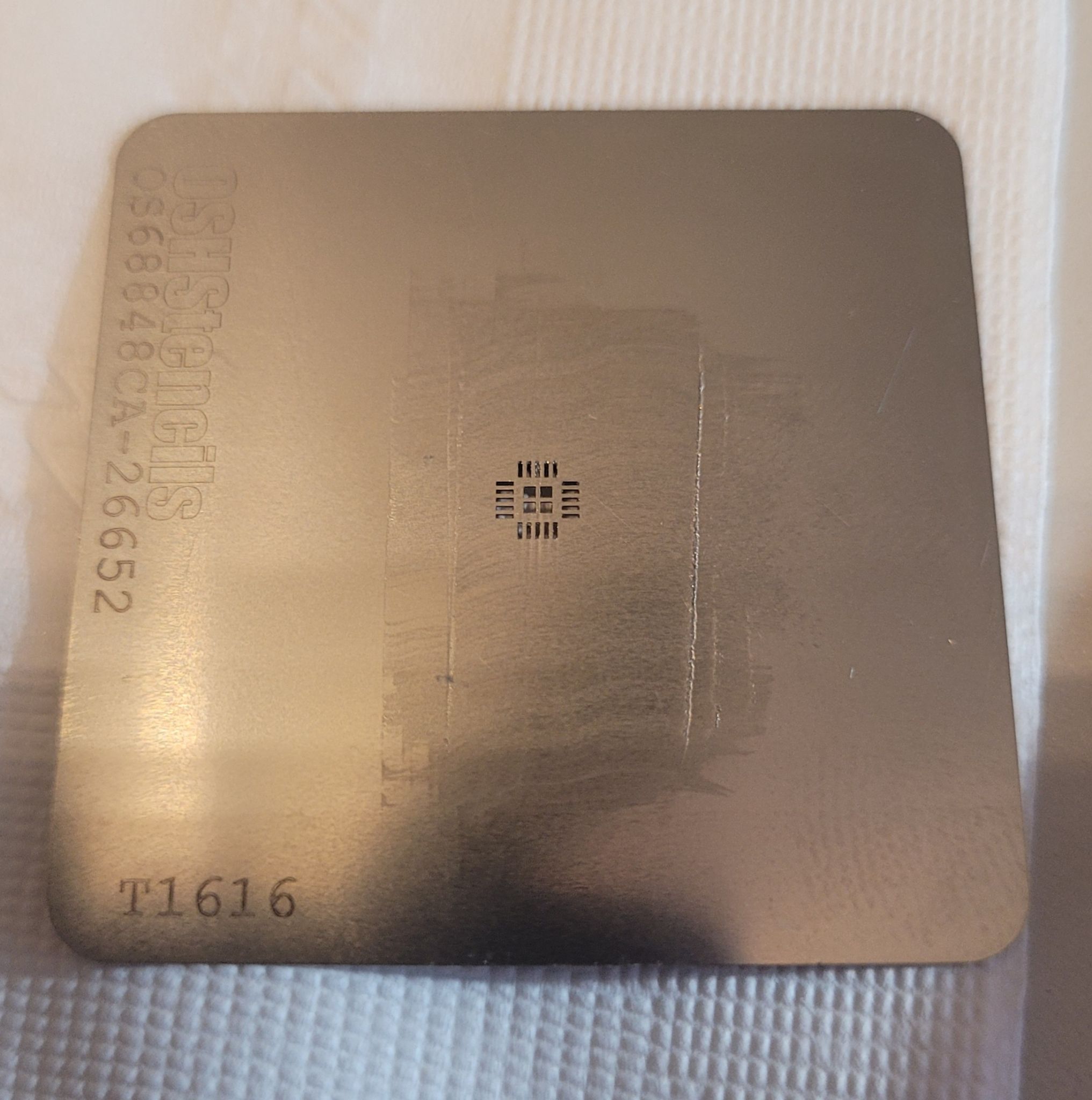
Did you use a stencil? If so which thickness?
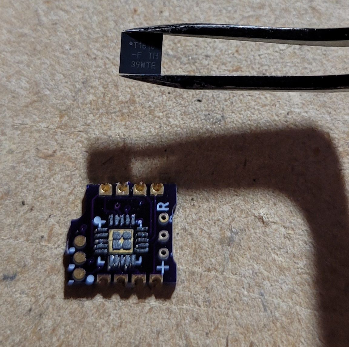
I feel that 4mil is too thick and the T1616 floats on a Sea of solder.
Yeah that Red looks Sweet!
Are they 660nm?
That looks great!
What clip is that?
1 Thank
its a Lumintop E05C clip.
2 Thanks
Personalized. I like that. what power source? driver?
Nope, nothing stencil.
I bought all soldered from JLCPCB
1 Thank
I got the 12” strips from Amazon, four strips of 18 5050 sized emitters. No indication of wavelengths.
No driver, there are resistors at each emitter or each set of three, with solder contacts … cuttable in sections of three emitters.
I’m presently using a Nitecore SCL10 light panel/battery bank (10,000mAh) to power these, with a type C USB out to 12V plug. Supposed to be getting an Anker 24,000 mAh battery bank today with multiple outlets. Just have to look for PD outlets that can supply 12V output.
The four red strips pull 6.6 watts (about .51A) and the Blue set pulls 5 watts (about .43A) So, together… 8 strips and 144 emitters… these pull about 1A at 12V.
1 Thank
A .1mm (.004") thick stencil is supposed to be fine for .3mm pitch leads and 0402. The 1616 MCU has a .4mm pitch.
1 Thank
This is the first stencil I’ve ever used, do you recommend a different thickness for the T1616?