Just a humble advice.
When the gasket fits too tight to put it in with little force I usually trim the internal edges of the gasket (e.g. with a hobby knife) to make them more round. This should solve the problem in most cases. It appears there are some slight dimmensions deviations among standard dimensions.
That’s a great tip, thank you! I will do this with my next XHP50.3hi.
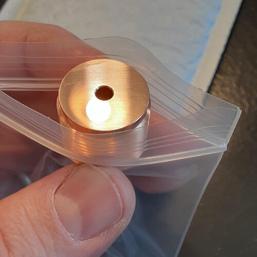
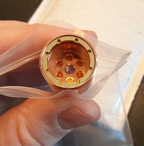
In this case it would likely not have helped, as this was an odd gasket that overlaps with the emitter itself due to the 7mm reflector opening being more narrow than the emitter diameter.
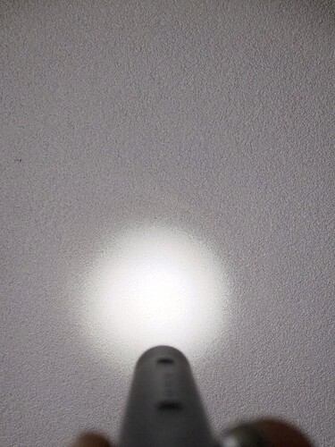
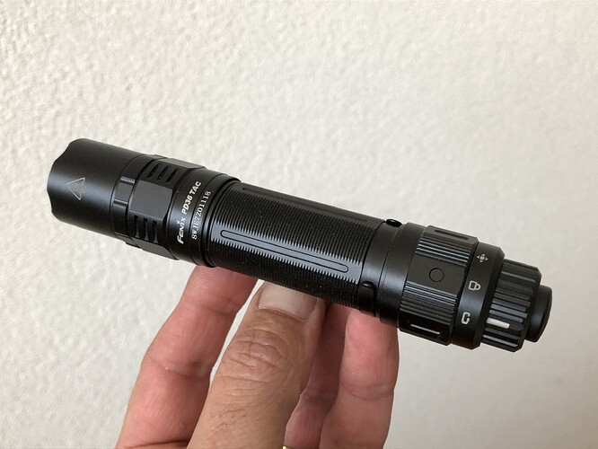
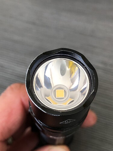
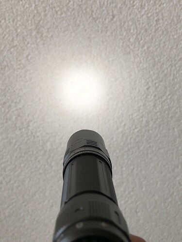
SwPped emitters on 47 Bolt and Fenix PD36TAC.
47 now has Yinding 6000K 98CRI emitter.
Fenix, since it’s underdriven, got Nichia B35 6500K 98CRI
I’ve posted about this issue in the past: Convoy S2+ Pill Issue - Shelf Not Flat
Since then, I always check the pill shelf to make sure it’s flat, along with the MCPCB.
I haven’t had an issue for years, so I’m surprised to see this again. ![]()
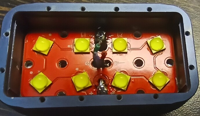
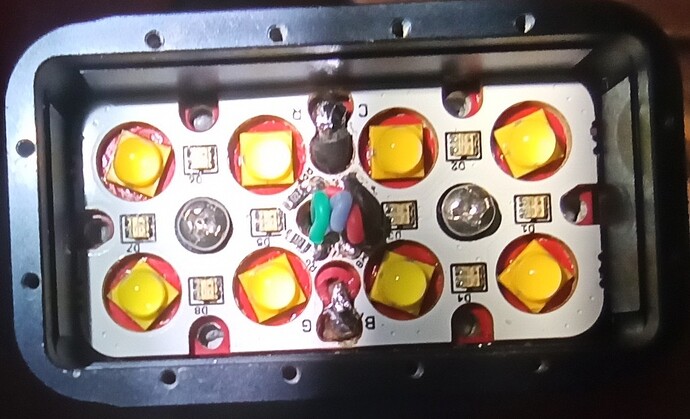
I’ve had Luxeon V’s in my storage box for a while. 4000K’s and 5700K’s. Today I decided to mod my Emisar DT8K with them. Goal was to test the maximum turbo output.
Reflowing them wasn’t easy on 3535 board, but I managed to do it anyway. I went with 4x4000K and 4x5700K. I also modded the host by adding additional hole for aux wires. That allowed me to use 18awg led wires in place of the stock 22awg ones.
It made the assembly much easier, aux wires had plenty of room. One leg needed to be cut from each optic.
Turbo peaked at bit over 40A with fresh battery. This is third turbo run startup.
Beam is very floody, as expected, but it still has hotspot. CCT is rosy and ~4500K.
Nice mod. I hadn’t realised how close to the inner edge those holes are for the bezel!
After modding a copper FW3C with a lume1 driver and single-colour green AUX LEDs (here), I still had another lume1 driver with damaged RGB AUX connector pads. I planned to use this one for another mod with single-colour AUX LEDs.
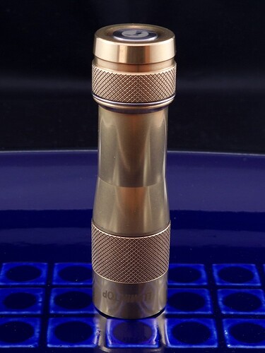
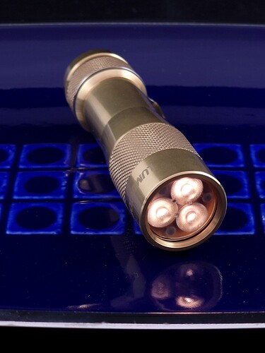
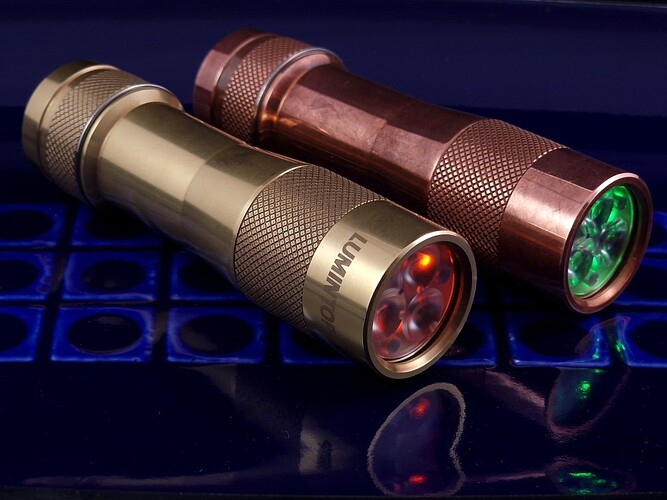
Some time ago, I got hold of a brass FW3A and planned to mod it with warm emitters and orange AUX LEDs. My other brass lights also have orange AUX and in my opinion it’s the nicest AUX colour for brass lights. In the weeks the light has been waiting for the parts to arrive, it’s developed a nice, smooth patina, which I like better than the polished shininess it had out of the box:
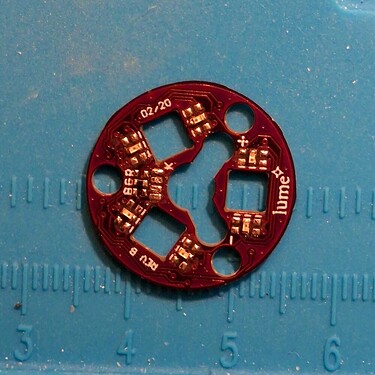
For this one, I didn’t want a not-quite-orange yellow colour from mixing red and green channels on an RGB AUX board, so I sourced some orange LEDs and a lume Tri-LED AUX board to mount them on.
This was a very slow piece of work, those LEDs are tiny and the resistor even more so.
I swapped out the original 6500K XPL-Hi emitters with 2700K SST-20 emitters to give the light a nice, warm beam to match my other brass lights and put in the Carclo 10508 frosted, medium spot optic to give a floodier beam.
Finally, as for the copper light, I’m using my custom Anduril 2 build for the lume1 driver, with UI modified for single-colour AUX LEDs.
It’s turned out as well as I’d hoped it would…
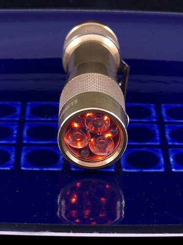
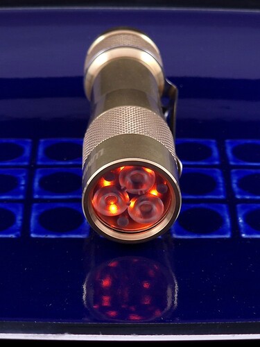
The orange AUX are lovely, either behind the default or the frosted optic:
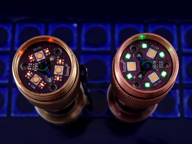
The positioning of the AUX is different with the Tri-LED AUX board (left), compared to the RGB AUX board (right):
Together with the FW3C, this makes a wonderful pair of lights:
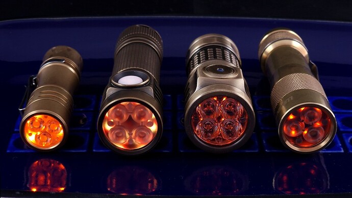
This picture shows the difference between using real orange AUX LEDs rather than relying on the mixed Red and Green of RGB AUX:
The left-middle light is my brass D4V2 with RGB AUX set to yellow/orange, the right-middle is a PL09 Quad with orange AUX LEDs and the right-hand light is the new brass FW3A mod. On the left is a brass TS10, on which the high AUX LED setting is far too bright.
Agreed, those sure are some tiny orange LEDs!
I’m curious to know how many milliamps you set them to.
Wow that is quite a lot of current. What battery was it?
I’m curious how it might compare to using the flip-chip XP-L HI that Convoy has stocked.
I did struggle with working out what mA value to aim for and as a result what resistor to use. I couldn’t find any definitive information on how to work this out, until I stumbled upon a thread here in BLF: click.
I used that as the starting point for a rough first estimate. A D4V2 has 8 AUX LEDs per colour, so from that I could estimate the current per individual AUX LED for the D4V2.
The Tri-LED AUX board for the FW3A has 6 LEDs per colour, so I could estimate the equivalent current for an FW3A. Here’s the result:
| Colour | D4V2 high (mA) | per AUX LED | FW3A high (mA, estimate) |
|---|---|---|---|
| Red | 3.00 | 0.38 | 2.25 |
| Green | 1.26 | 0.16 | 0.95 |
| Blue | 1.35 | 0.17 | 1.01 |
Note that the mixed colours have higher current due to the mixing of multiple RGB LEDs, so only the values for R, G, B can be used further calculations (hence the strike-throughs).
That doesn’t include orange, so I made a guess that, since orange is close to red on the visible light spectrum, I should choose a current value close to, but less than, red.
Hence, I chose 2.20mA as the estimate for my calculations for orange, which lead to a resistor estimate of ~180Ω (Vfwd for the LEDs I sourced is 2.1V). Since personally I think the D4V2 AUX brightness is a little too bright, I chose a 220Ω resistor as the starting point for my FW3A.
Since the above is not exactly precise, I was expecting that 220Ω would be the starting point and I’d be trying different values above and below that to find the best value. However, I was so pleased with the result with a 220Ω resistor, I stopped with that. So either the above method is genius (in which case, pat myself on the back), or it was a complete coincidence that 220Ω happened to be a good value (in which case, shhh, and don’t mention that 220Ω is the value for red AUX after shuffling the resistors for the Lume1 driver, so 220Ω working well for orange isn’t really a surprise, is it?).
Yeah, would be interesting to see those tested. I did small and fast VF test for them few years back, but I don’t have equipment for lumen measurements.
Are you gonna be selling these?
Thanks for the info.
For my red and orange lighted tailcaps, I run around 0.45mA. They certainly are more power hungry than the blues, whites, pinks, warm whites, greens, etc.
For me, it’s just a trial and error to get to the brightness I want. I like to have all my tailcaps at a similar brightness. And the resistance needed not only depends on the LED or combination of LEDs, it also depends on the driver.
And even the same color can be different depending on who manufactured them. I have greens and blues that are distinctly different from each other.
I thought you would’ve just used a DMM to measure the current. Maybe that’s hard to do with the FW3A?
Wow, they definitely are amazing! ![]()
On Anduril lights the MCU makes a big difference.
The T1634(Hank[pre D3AA] and Lume) uses way different resistors than a T85 or T1616.
On Mechanical switch lights the bleeder resistor value plays a big role.
If there’s a complicated way of doing something, that’s the one I usually think of first. So the DMM idea didn’t even cross my mind. ![]()
With a DMM I measure the following on a couple of FW3As.
FW3A with lume1 and RGB AUX board, after the resistor shuffle
- Red AUX: 2.71mA
- Green AUX: 0.75mA
- Blue AUX: 0.42mA
FW3C with lume1 and RGB AUX board, after the resistor shuffle
- Green AUX: 0.77mA
Brass FW3A with lume1 and Tri-LED AUX board
- Orange AUX: 2,64mA
Edit: I also measured the current for the 16 orange AUX LEDs on my PL09 Quad (also shown in the photo above): 5,37mA
I’ll be putting some in a DT8K at some point, I’ll compare it against W2 when it is ready.
