Have a nice time here, BlackWolf!

1 Thank
I’m in for one if this is still the place to get them. PM sent
Received mine yesterday.
PM envoyé et bienvenu sur BLF!
No such luck here. Found my old 3.3V adapter (same writings on the back as in your picture) but can’t even read the firmware from my D3AA w/ 519A 5700K dedomed.
I’m going to try that mod, as I can’t do #1 right now (no access to a soldering iron). What capacitor value did you use? All I can see in the picture is “680uF”, but the first digit is not clear and I think I may have missed more digits before it.
@thefreeman, what value do you recommend for that capacitor, for my specific case?
TIA!
No, you‘re absolutely right. It’s a 680uF/ 16V capacitor, there are no digits missing.
3 Thanks
Thanks! Will try and procure one tomorrow at a nearby electronics shop.
2 Thanks
I’m interested in knowing if that works for you. Keep us posted.
1 Thank
Will do! Just managed to buy two of these capacitors (only one should be needed, but costing less than 20 cents each, I thought it best to buy 2 and save one as a spare), will know whether it works momentarily.
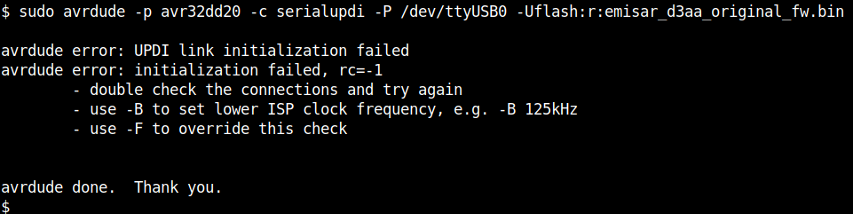
EDIT: no such luck. The adapter’s behavior on my light definitely changed (no more turning off and then back on of its LED when connecting to the D3AA), but I tried to read its firmware a dozen times and except once, this was the result:
The exception was this time, when it almost worked:
The ^C after the error message was me interrupting the program about 1 minute after the “page load” error message with no updates.
Here’s how I rigged it:
Next thing I’m gonna try is to use both capacitors in parallel (I bought 2 after all) in the hopes that twice the capacitance is enough to bump things over into working.
Any further suggestions welcome.
1 Thank
Sorry for not replying sooner but increasing the output capacitance is not super reliable, it’s just easy to try if one has a capacitor lying around
2 Thanks
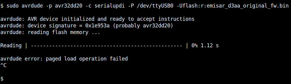
Unfortunately the same error with double capacitors. Here’s how it looked:
I know the double capacitors are correctly connected because the on-board LED now takes longer (many seconds, about twice than with a single capacitor) to turn off when I disconnect the adapter from the computer’s USB port (ie, it’s serving its function of ‘current reserve’). But that’s apparently not enough… :-/
Also, I’m pretty sure there are no shorts etc because the rigged adapter still works with my TS10 with no issues.
Only now you tell me ![]()
Seriously, no problem and thanks for your input.
One question: is connecting +5V instead of 3.3V (ie, mod #1 as per your post), more reliable than the capacitor thing? If so I will try and procure a soldering iron, solder and a wire to try it next.
Yes, no problem when the driver is powered with 5V
1 Thank
I tried and unfortunately the only kind of soldering iron I can find locally is blunt-tipped, no way I can solder the wire at the U2 pin with it.
Looks like I’m gonna have to wait for my new 4.5V adapters to arrive… ![]() not really thrilled at my chances, this being Brazil and me without a tracking number. But anyway I tried everything else, so all that’s left is the wait
not really thrilled at my chances, this being Brazil and me without a tracking number. But anyway I tried everything else, so all that’s left is the wait ![]()
1 Thank
I didn’t see any bashing. He was just trying to make an adapter work until he does get the 4.5V models that he ordered…
Which would be apparent if you had read the entire story…
Besides why do you take offense when thefreeman doesn’t seem to? I am sure he could defend himself and his product if he felt it was required.
Relax… please.
BTW, I was interested in his results as I have some of the older 3.0 V units. I was curious to see if doing the capacitor mod may make them work as well as the newer ones.
3 Thanks
Today I woke up with an idea: to try and get someone else to do the mod for me. In fact, there are cellphone repair shops practically in every street corner around here, and these shops deal with much more minute/delicate electronics (the ones inside cellphones) so I was confident that they could do the job. Then I selected a nearby shop with good reputation from GoogleMaps and headed there.
The good news is, in the end IT WORKED! YAY! Finally I can backup my original firmware and config, and update my D3AA! ![]()
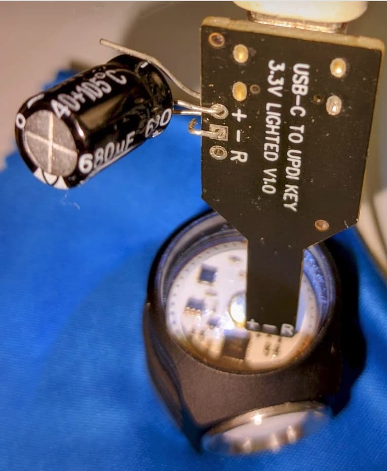
The not so good news is, it demanded a LOT of effort. The guy at the shop was very knowledgeable and had all the right tools, but I did not notice that the picture @thefreeman originally posted has the “+” and “R” pins reversed in relation to the ones in my adapter ![]() so initially he did the mod to the wrong pin (the “R” one) instead of the correct “+” pin)…
so initially he did the mod to the wrong pin (the “R” one) instead of the correct “+” pin)…
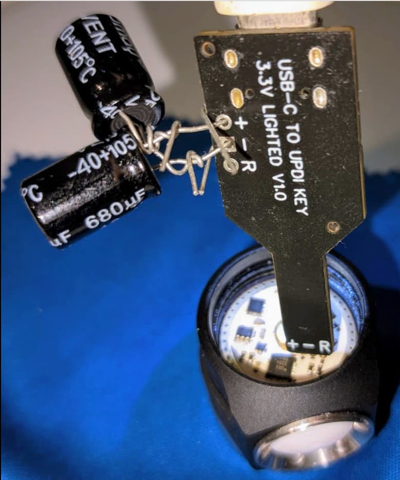
Also, when he cut the copper trace connecting the “+” pin to the rest of the circuit, the onboard PWR LED would no longer light up… turned out that the LED is powered from that copper trace too, so if you don’t want it to go off permanently, you have to cut the trace very close to the “+” pin.
Fortunately the cellphone repair guy was not only knowledgeable but also very patient, and so he undid the mod to the wrong pin, then did it to the right pin, and then (when the PWR LED refused to turn on) traced the board with a DMM and diagnosed and fixed the issue (by reconnecting the trace where he first cut it, and then cutting it again at the point I indicate below).
For easy reference, here’s @TheFreeman’s picture, along with a photo from my adapter, depicting both issues:
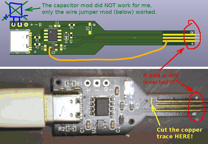
I hope this helps other people avoid these pitfalls… ![]()
EDIT: changed the picture to try and make it clear that in the end what worked was the wire jumper mod alone – no capacitors in my final setup.
2 Thanks
Just want to clarify - did the addition of the capacitor WITHOUT the addition of the wire jumper work? Or did you incorporate both changes at the same time? Thanks for sharing.
1 Thank
Nope – absolutely no go with the capacitor, in my case.
What worked – once the two caveats I pointed to were taken care of – was the wire jumper.
Or did you incorporate both changes at the same time?
I followed @thefreeman’s direction and did not try both – and it wasn’t necessary, just the wire jumper (done correctly) was enough to get it to work.
Thanks for sharing.
No problem, I’m glad to be of help ![]()
EDIT: I’ve just changed the picture in my post above to try and make that more clear, thanks for pointing the possible confusion to me.
congrats on getting your TS10 flashing adapter, adapted to work w your D3AA
Will a D3AA adapted adapter still work on a TS10? ![]()
My TS10 flashing adapter does not work on my D3AA, so earlier today I ordered a new one from gchart.
He had asked if my adapter had holes in it, so I could try the capacitor trick… but, no, my adapter does not look like yours, nor do I have any capacitors.
Could my TS10 adapter be modified to work on my D3AA by adding a wire like you did? and if so, can you markup this pic with the correct changes? Do I also have to cut a trace?
1 Thank