Wuben kindly sent the E7 for review.
There’s an optional headband, optional sensor for handsfree operation, and an optional 18650 extension tube.
It’s a bit like the Wuben X0 but there are some big differences.
Here is my review:
Wuben kindly sent the E7 for review.
There’s an optional headband, optional sensor for handsfree operation, and an optional 18650 extension tube.
It’s a bit like the Wuben X0 but there are some big differences.
Here is my review:
Great review, thank you for sharing.
I do have a question for you. Are the two optics individual pieces are all in one? Also, how tall are they? They seem to be very flat/thin.
Thanks
The optic is one big piece. I’ll measure it tonight.
Of the similar headlamps you have tested would you recommend this ot another for garage work? It looks really nice from that review but it has so short runtime that I would be using it with a 18650 extension so thst brings size up to all the other headlamps
Armytek Wizard C2 Pro Nichia is pretty good. Floody nice beam. Strong magnet. Excellent regulated output.
I haven’t done a full review of this Nichia model but I prefer it over the WR due to the floodier beam.
The TIR optic is 3.76mm thick. The two feet extend the thickness to 4.56mm.
16.25mm * 31.24mm * (3.76mm to 4.56mm).
Height * Length * Thickness.
Thank you!
I am impressed as to how incredibly shallow the optic is compared to your typical reflector or TIR.
Are there any artifacts or tint shift in the beam?
No noticeable tint shift with these cool white emitters.
There are artifacts like the X3 but the two emitters cancel it out.
With the X3 there’s a square pattern in the middle due to the shallow optic and due to having one white and one red emitter.
The E7 has two white emitters so the spill of each overlaps the square pattern and this results in a smooth oval shaped beam.
Thanks again for all of the great info. Does the X0 have any artifacts or tint shift?
The X0 doesn’t really have any artifacts or tint shift. The reflector is a bit bigger. It is throwier but the beam is smooth.
Wuben kindly sent the neutral white version of the E7.
The CCT of the Wuben E7 Neutral White is around 4917K. The CRI is around 69.
The Delta u, v is positive (green).
| Mode | CCT (K) | CRI (Ra) | x | y | Duv |
|---|---|---|---|---|---|
| Low | 4818 | 69.1 | 0.3516 | 0.3661 | 0.0046 |
| Med | 4912 | 69.3 | 0.3487 | 0.3648 | 0.0051 |
| High | 4925 | 69.2 | 0.3483 | 0.3641 | 0.0049 |
| Turbo | 5015 | 69.7 | 0.3454 | 0.3599 | 0.0040 |
The CCT of the Wuben E7 Cool White is around 6600K. The CRI is around 73.
The Delta u, v is slightly positive (green) on lower modes and close to pure white on Turbo.
The beam has a smooth white oval-shaped hotspot with a slightly green corona and a spill that fades outward.
| Mode | CCT (K) | CRI (Ra) | x | y | Duv |
|---|---|---|---|---|---|
| Low | 6293 | 71.7 | 0.3163 | 0.3326 | 0.0033 |
| Med | 6584 | 74.0 | 0.3117 | 0.3257 | 0.0020 |
| High | 6616 | 74.0 | 0.3113 | 0.3249 | 0.0018 |
| Turbo | 6921 | 74.9 | 0.3072 | 0.3185 | 0.0006 |
An unprotected cell may be shorted if a battery is inserted in reverse. This will damage the driver and it could cause a fire.
The included protected 18350 cell works as expected and did not get warm or damage the driver.
I inserted an unprotected 18650 cell in reverse, screwed the tailcap on, and the torch started to smoke! The driver has been burnt and no longer works.
While reviewing the Wuben E7, I noticed the tailcap spark when I tried to put the tailcap on with an 18350 cell inserted in reverse but nothing else happened. I asked a few community members and they weren’t able to reproduce this issue.
Wuben sent a second Wuben E7 (neutral white). This time I tried to insert an unprotected 18650 cell in reverse and the driver started smoking. The torch became warm to touch and it no longer works.

Wuben recommends using a protected 18350 or 18650 cell.
Wow, this seems like a big oversight. I know it’s not a huge deal to use protected cells, but its hard to imagine a modern light without reverse voltage protection.
At this stage of the game, 2024… no flashlight maker should be producing flashlights without polarity checks built in. Cell inserted incorrectly should simply refuse to work, protecting the circuitry and the cell. Really a shame on you, Wuben. You should know better!
It looks like reverse polarity protection works on the updated version. The driver has R7-B3 on it near the spring.
I bought this E7 on sale to check RPP.

Where did you buy the updated version from?
I just placed an order on Amazon AU from the “Newlight AU” seller (which seems to only sell Wuben, so maybe their Amazon AU storefront?)
Will post here if they have shipped the updated driver.
Currently 44% off (main light only, extras still full price)
I ordered from the same store a few weeks ago when it was on sale.
received today, all have the updated E7-B3 PCB with reverse polarity protection (also checked for function)
S/N:
E73722729 - tan 6500K
E73722754 - tan 6500K
E736317253 - black 5000K
E736317269 - black 5000K
(not a typo)
going to attempt an emitter swap with 519a and post comparison beamshots.
Just bought one of these. I really like the form factor and build quality, but not the UI so I decided to look into making a custom driver for it. I’ve taken it completely apart and thought I’d share some details.
There are two PCBs, held together by 4 pins. The front PCB can be removed by desoldering the 4 pins and the LED connections. The back PCB is then held in by a threaded pill in the battery tube.
Back PCB:
The ICs at the bottom are the reverse polarity protection MOSFETs. This board is marked E7-B5.
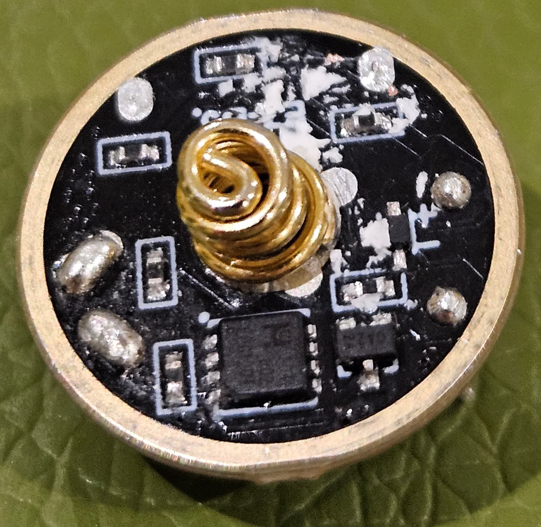
On the other side is a boost converter:
Turns out I’m not yet allowed more than one image per post, so other images posted here: Index of /images/wuben-e7
It took me a while to figure this one out, but the boost converter is to provide a 5V supply on the USB-C port for the sensor accessory. I can’t find any details on the IC, but it appears to be a combined charge controller and boost regulator. When you supply 5V on what is normally the 5V output, it starts charging at up to 1A, and pin 3 shows the charge status (low = not charging, alternating = charging, high = fully charged).
Interestingly, this boost regulator is on all the time and accounts for pretty much all of the 0.1mA standby current. I presume this IC has a low-voltage cut-off, but i think it’s an interesting compromise to have an extra boost converter and a relatively high standby current to support an accessory which I suspect most people won’t use.
The boost converter means you can actually use the flashlight as a power bank for some devices - they have to be stupid devices that ignore the signal on the CC pins that indicates that the device is a current sink only.
The signal from the external sensor appears to be on the D+/D- pins, which are shorted together, so I’m guessing it’s a very simple high/low signal rather than any digital protocol.
The four pins that rise to the other PCB are GND, Battery +ve, charge status and sensor signal.
The front PCB is more straightforward. The front has an FMD microcontroller, switch, and 2 color LED. I’ve not identified the top left IC - possibly an op-amp?
The back has the driver. The IC is marked EABGdA, but I can’t find any info on it.
The inductors on the two boards are a tight fit once the boards are together.
I’m planning to make a custom driver to replace the top board. I might do the other one too to get rid of the silly standby current, but I’ve not been able to find a source for the USB C ports.