You are right, for some reason I thought that it use the same MCU…
Anyway I have A17-DD driver with attiny25, so at least swapping it for 85 should be easy ![]()
I don’t know if this is right topic for my questions, but it seems like, so here they are.
1) I got D4V2 with KR4 CC 5A driver (LED - Nichia 219c) and have noticed that it seems like main channel and FET are active together when FET is active (config file - cfg-noctigon-kr4-219.h) - why it is like that? I may be wrong, but shouldn't it be like FET only?
// don't turn off first channel at turbo level
#undef PWM1_LEVELS
#define PWM1_LEVELS 0, ... ,1023
2) I have compared config files for kr4 (cfg-noctigon-kr4.h) and original driver d4v2 (cfg-emisar-d4sv2.h) and found those difference, which makes me question why it's like this (exept differences in configs that I can undestand, like AUX LED in button, soft reset with button and so on - wich root cause are hosts possibilities)
D4V2:
// stop panicking at ~30% power or ~1200 lm
#define THERM_FASTER_LEVEL 105
KR4:
// stop panicking at ~25% power or ~1000 lm
#define THERM_FASTER_LEVEL 100
#define MIN_THERM_STEPDOWN DEFAULT_LEVEL
#define THERM_NEXT_WARNING_THRESHOLD 16 // accumulate less error before adjusting
#define THERM_RESPONSE_MAGNITUDE 128 // bigger adjustments
So, I see different thermal settings and the question is - this difference due to bigger kr4 thermal mass, or the driver itself? In other words, should I change them for my light like in original d4 config (remove them, so ones from fsm will be taken)?
Why 51 for 100/150?
Because 1 is 150.
For 1), this is a totally different driver than a FET+1 - the main LED PWM is not PWM'ing output directly, like it does on 7135's. The very last level has both turned ON probably for a good reason that TK would know best.
For 2), I assume she custom tweaked the settings for the KR4, as she did for the Emisars. Driver and light are both important
If it was me, my best guess would be for your setup of a KR4 driver in a D4V2, I'd go with the KR4 settings.
Thank you for your answer!
For 1 - I tried it myself (disable 1st channel when turbo on and get very weak turbo - so that’s the reason
For 2 - I’ll tried both config entryes and see no difference, so I continue with KR4 config
Hi, i have not found another place for my question. If it’s wrong place i am so sorry, please move. So…
(Fireflies E07)
I measured my room temperature with Fluke… 21C°
I want to calibrate temperature so 21 clicks in current temperature mode.
I left the light overnight.
Next day i want to measure temperature and this is happen…
The first cycle of blinks are 21C° , the second cycle are 16… between the first cycle and second i do not shut off the light… the room temperature is 21
(FW3A)
Now I have set the temperature to 18 (room is 18C°)
Shut off the light…3 clicks than temperature mod… 21 blinks ![]()
Why?
is correct?
The thermal sensor must give me the room temperature or the light temperature?
I don’t understand so ask to community
Thank you
Before you set room temp in the flashlight, you must do your best to get the flashlight at room temp - that means leaving it sit off for maybe an hour or 2 before setting the temp, and even when you do be sure the light never accidentally goes to a hi mode. What I do is to be sure to press&hold to turn it on at the lowest, ramp up very slightly - turn it off. This assures a lo output when doing the 3 clicks to get into voltage display, then 2C's from there.
Also the first blink of temp is not accurate - thought TK fixed this in a more recent Anduril, maybe just in Anduril2? Not sure. Let it blink out temp 2 times to get a good reading.
I leave overnight… maybe 8H
Why?
Not mine I think
The sequence you described was leaving it over night "after" it was calibrated - you need to stabilize the flashlight temp before calibrated.
Yes, because I have already calibrate one time before i write the first post
I am so sorry for my English… I will try another time and upload thread.
When I was calibrating my SC31pro, just holding it in my hand had the temp increase (on blinkout) 1° and then 2° in just a minute or two, so you need to do it fast. And keep the light overnight right next to a thermometer so you can see at a glance the temperature and let both equilibrate.
Next day or however long, go immediately to the temp blinkout and verify what it tells you vs the thermometer temp. If too different, then again, immediately do the calibration, and another temp blinkout to verify that it stuck.
21°C, holding it in a 37°C hand, it’ll warm up a few degrees very quickly.
Ahh, ok. I forgot the details but I think the first reading was perhaps a bug.
As LB said, it's very sensitive. All these calibration issues go away with the Atmel 1-series (1616, 3216) since they are factory calibrated.
Hi! Could you tell me, https://bazaar.launchpad.net/~toykeeper/flashlight-firmware/fsm/view/head:/ToyKeeper/spaghetti-monster/anduril/cfg-ff-rot66g2.h applied for any ROT66 II on factory (with any Leds?)
And please, could you tell me config for EDC18 and Astrolux HL01
Thank you!
Damn God.
In ~toykeeper/flashlight-firmware/trunk : contents of PRODUCTS at revision 249 HL01 should be Anduril / cfg-mateminco-mt07.h
BUT in ~toykeeper/flashlight-firmware/trunk : files for revision 247 no such cfg file
So, is there any way to discover settings for Astrolux HL01?
Sorry, don't own a HL01, if I did, you'd have the info you want. Dunno if anyone did a tear down to provide details on the driver. Once we know the driver, could probably get the proper Anduril build for it. Unfortunately, Astrolux hasn't communicated well back the the community so TK probably isn't aware of the HL01's Anduril setup.
For the EDC18, I'm sure I have, or could make an Anduril cfg file for it. Just checked - back in April 2019 I did a custom config for Anduril 1.1 on the EDC18, adding support for the AUX/switch LED. I rewired the switch LED so Anduril controls it.
Thank you for your answer. Is this modding reviewed anywhere here in detail?
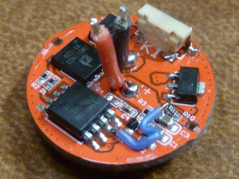
Hhhmmm, good Q. Here's my EDC018 pic album: https://app.photobucket.com/u/TomE2012/a/a12dfc4e-d6a7-4530-8520-0dbfc3591a50
It shows the mod.
you just add this wire to 1 leg of controller?
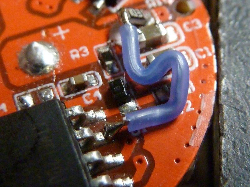
Sorry, was at work - home now. Reviewed and trying to recall (at my age, that can take a while...). This is what I did:
- Removed R4 - was connected to pin #7 and does nothing anyway (from TK's experimenting with detecting input from the main LED)
- Removed R10 - original hard wired resistor for the switch LED
- solder in a 10K resistor, tomb-stoned -- be sure there's no contact to the "+" pad
- solder a 30 AWG wire from pin#7 to the 10K
So, the end result, as shown, is I got a switch surface mount LED connected to MCU pin #7, with a 10K resistor in between, as shown:
Now Anduril has to be tweaked to support this hardware configuration. So this is the Anduril hwdef file I used, hwdef-EDC18.h:
#ifndef HWDEF_EDC18_H
#define HWDEF_EDC18_H
/* BLF/TLF EDC18 driver layout
*
* The Lumintop EDC18 is basically the same driver as used in the FW3A, but has the e-switch mounted on the driver PCB.
* For my custom EDC18, I removed the resistor off of PIN #7 for the "optic nerve" and wired a jumper to the switch LED
* resistor - using 10K for now, and had to tombstone the resistor to break the connection to Batt+. This will allow
* Anduril to control the switch LED from pin #7
* ----
* Reset -|1 8|- VCC
* eswitch -|2 7|- switch LED (0402 under the switch with 10K 0603 resistor, removed (20K 0402)
* FET -|3 6|- 7x7135
* GND -|4 5|- 1x7135
* ----
*/
#define PWM_CHANNELS 3
// ... the modded EDC18 has aux switch LED on pin 7
#ifndef AUXLED_PIN
#define AUXLED_PIN PB2 // pin 7
#endif
#ifndef SWITCH_PIN
#define SWITCH_PIN PB3 // pin 2
#define SWITCH_PCINT PCINT3 // pin 2 pin change interrupt
#endif
#ifndef PWM1_PIN
#define PWM1_PIN PB0 // pin 5, 1x7135 PWM
#define PWM1_LVL OCR0A // OCR0A is the output compare register for PB0
#endif
#ifndef PWM2_PIN
#define PWM2_PIN PB1 // pin 6, 7x7135 PWM
#define PWM2_LVL OCR0B // OCR0B is the output compare register for PB1
#endif
#ifndef PWM3_PIN
#define PWM3_PIN PB4 // pin 3, FET PWM
#define PWM3_LVL OCR1B // OCR1B is the output compare register for PB4
#endif
#define ADC_PRSCL 0x06 // clk/64
// average drop across diode on this hardware
#ifndef VOLTAGE_FUDGE_FACTOR
#define VOLTAGE_FUDGE_FACTOR 7 // add 0.25V
#endif
//#define TEMP_DIDR ADC4D
#define TEMP_CHANNEL 0b00001111
#define FAST 0xA3 // fast PWM both channels
#define PHASE 0xA1 // phase-correct PWM both channels
#define LAYOUT_DEFINED
#endif
This is the Anduril cfg file I used:
// EDC18 config options for Anduril
#include "hwdef-EDC18.h"
// the button lights up
#define USE_INDICATOR_LED
// the button is visible while main LEDs are on (2020-02-09 TE: enable this!!)
#define USE_INDICATOR_LED_WHILE_RAMPING
// enable blinking indicator LED while off
#define TICK_DURING_STANDBY
#define STANDBY_TICK_SPEED 3 // every 0.128 s
#define USE_FANCIER_BLINKING_INDICATOR
// off mode: low (1)
// lockout: blinking (3)
#define INDICATOR_LED_DEFAULT_MODE ((3<<2) + 1)
// ../../bin/level_calc.py 1 65 7135 1 0.8 150
// ... mixed with this:
// ../../../bin/level_calc.py 3 150 7135 1 0.33 150 7135 1 1 850 FET 1 10 1500
#define RAMP_LENGTH 150
#define PWM1_LEVELS 1,1,2,2,3,3,4,4,5,6,7,8,9,10,12,13,14,15,17,19,20,22,24,26,29,31,34,36,39,42,45,48,51,55,59,62,66,70,75,79,84,89,93,99,104,110,115,121,127,134,140,147,154,161,168,176,184,192,200,209,217,226,236,245,255,255,255,255,255,255,255,255,255,255,255,255,255,255,255,255,255,255,255,255,255,255,255,255,255,255,255,255,255,255,255,255,255,255,255,255,255,255,255,255,255,255,255,255,255,255,255,255,255,255,255,255,255,255,255,255,255,255,255,255,255,255,255,255,255,255,255,255,255,255,255,255,255,255,255,255,255,255,255,255,255,255,255,255,255,0
#define PWM2_LEVELS 0,0,0,0,0,0,0,0,0,0,0,0,0,0,0,0,0,0,0,0,0,0,0,0,0,0,0,0,0,0,0,0,0,0,0,0,0,0,0,0,0,0,0,0,0,0,0,0,0,0,0,0,0,0,0,0,0,0,0,0,0,0,0,0,0,2,4,6,8,10,13,15,17,19,22,24,26,29,31,34,37,39,42,45,48,51,54,57,60,64,67,70,74,77,81,85,88,92,96,100,104,108,112,116,121,125,130,134,139,143,148,153,158,163,168,173,179,184,189,195,201,206,212,218,224,230,236,243,249,255,255,255,255,255,255,255,255,255,255,255,255,255,255,255,255,255,255,255,255,0
#define PWM3_LEVELS 0,0,0,0,0,0,0,0,0,0,0,0,0,0,0,0,0,0,0,0,0,0,0,0,0,0,0,0,0,0,0,0,0,0,0,0,0,0,0,0,0,0,0,0,0,0,0,0,0,0,0,0,0,0,0,0,0,0,0,0,0,0,0,0,0,0,0,0,0,0,0,0,0,0,0,0,0,0,0,0,0,0,0,0,0,0,0,0,0,0,0,0,0,0,0,0,0,0,0,0,0,0,0,0,0,0,0,0,0,0,0,0,0,0,0,0,0,0,0,0,0,0,0,0,0,0,0,0,0,0,8,19,31,43,55,67,79,91,104,117,130,143,157,170,184,198,212,226,240,255
#define MAX_1x7135 65
#define MAX_Nx7135 130
#define HALFSPEED_LEVEL 14
#define QUARTERSPEED_LEVEL 5
//-----------------------------------------------------------------------------
// Thermal Settings
//-----------------------------------------------------------------------------
// optional, makes initial turbo step-down faster so first peak isn't as hot
// the D4 runs very very hot, so be extra careful
//#define THERM_HARD_TURBO_DROP
// stop panicking at about 3A or ~1100 lm, this light is a hotrod
#define THERM_FASTER_LEVEL MAX_Nx7135
// respond to thermal changes faster
#define THERMAL_WARNING_SECONDS 3
#define THERMAL_UPDATE_SPEED 1
#define THERM_PREDICTION_STRENGTH 4
//-----------------------------------------------------------------------------
// Set it much higher than the default of 70C
#define MAX_THERM_CEIL 80
I'll probably convert this over to work with Anduril 2. Also I got two more EDC18's to make this mod to.