I had to check this and flashed the version you’ve linked above onto my D4S. Result: Exact same behavior as intended and shown in my video. Turns on after a short delay and absolutely no flashes.
What ever happened to the optic nerve programming idea on the FW3A? Last I heard of it, they deemed it unreliable to use the LED as a photo receiver but does that mean 2 pin programming is a possibility? Could we adapt it to program a attiny1634 with 2 pins?
A mystery.
Here I first started from off, showing the flashes, then I blinked out the version number:

I have not compiled the hex myself, I’m not even able to. Also, I have no other source for hex files.
As far as I can see you have the delay as well. The flashes you are seeing are not the “flashes” from the legacy button timing, they look different. Your driver might have issues regulating low levels, maybe one of your 7135 doesn’t like the short pulses. Or the ramping table in the flash memory got corrupted (you could try to download the hex again, but it should contain checksums and the normal programming validates the flash as well).
Maybe. Likely? As I said, wenn I stop in the middle of those flashes, the light can go below floor level. I cannot explain this with a defect 7135.
At 1, I see actually nothing, then it comes on but is unstable. At 3, the light is stable and extremly dim.
Ok, so I should flash it again :weary:
Tried all floor levels up to 18, where the ramp started to become linear with a low enough floor level. Actually looks normal now, so I’ll leave it as it is. Thanks for your help and sorry for being such a noob. Need to learn much more about these things.
Is there a status page about the Andùril 2 project?
Sorry i haven’t followed this whole thread and i’m a bit confused. Is it done and available on some newer lights? What’s the feedback about it?
Just looking at some recent UI charts i got a headache…
I don’t know how accurate it is, but in the first post TK wrote this:
Granted, A2 has more commits on BZR since then, but AFAIK no new releases.
IMO it’s a nice progression from vanilla Anduril, but I like a few things changed from the stock A2 configuration.
I haven’t heard much about it in a long time. Another concern was speed: programming that way was time consuming, IIRC.
With the AVR 1-Series whose support recently made it into the main branch of Anduril2, you only need 3 pins: Power, Ground, and UPDI/Reset. That’s a lot closer to your “2 pin” programming.
I tried to disable Simple UI in my cfg-*.h:
#ifdef USE_SIMPLE_UI
#undef USE_SIMPLE_UI
#endif
But I was getting an error while running make due to some references to Simple UI in ramp-mode.c:
ramp-mode.c: In function ‘ramp_config_save’:
ramp-mode.c:425:26: error: ‘simple_ui_config_state’ undeclared (first use in this function)
     if (current_state == simple_ui_config_state)  style = 2;
                          ^
ramp-mode.c:425:26: note: each undeclared identifier is reported only once for each function it appears in
ramp-mode.c: In function ‘nearest_level’:
ramp-mode.c:480:41: error: ‘simple_ui_active’ undeclared (first use in this function)
     uint8_t num_steps = ramp_stepss[1 + simple_ui_active];
                                         ^
ramp-mode.c: In function ‘ramp_update_config’:
ramp-mode.c:508:9: error: ‘simple_ui_active’ undeclared (first use in this function)
     if (simple_ui_active) { which = 2; }
I fixed it by adding some conditions:
=== modified file 'ToyKeeper/spaghetti-monster/anduril/ramp-mode.c'
--- old/ToyKeeper/spaghetti-monster/anduril/ramp-mode.c 2020-10-17 02:45:24 +0000
+++ new/ToyKeeper/spaghetti-monster/anduril/ramp-mode.c 2021-04-19 00:31:52 +0000
@@ -422,7 +422,9 @@
// 0 = smooth ramp, 1 = stepped ramp, 2 = simple UI's ramp
uint8_t style = ramp_style;
-
#ifdef USE_SIMPLE_UI
if (current_state == simple_ui_config_state) style = 2;
-
#endif
// save adjusted value to the correct slot
if (value) {
@@ -477,7 +479,11 @@
// bounds check
uint8_t mode_min = ramp_floor;
uint8_t mode_max = ramp_ceil;
- uint8_t num_steps = ramp_stepss[1 + simple_ui_active];
-
uint8_t num_steps = ramp_stepss[1
-
#ifdef USE_SIMPLE_UI
-
+ simple_ui_active -
#endif
-
];
// special case for 1-step ramp… use halfway point between floor and ceiling
if (ramp_style && (1 == num_steps)) {
uint8_t mid = (mode_max + mode_min) >> 1;
@@ -505,7 +511,9 @@
// ensure ramp globals are correct
void ramp_update_config() {
uint8_t which = ramp_style; -
#ifdef USE_SIMPLE_UI
if (simple_ui_active) { which = 2; } -
#endif
ramp_floor = ramp_floors[which];

ramp_ceil = ramp_ceils[which];
Revision: 586
https://bugs.launchpad.net/flashlight-firmware/+bug/1925009
Guys I have a Anduril2 question for a D4v2 with KR4 driver (E21 emitters with a 7.5A driver) about PWM setting.
The default PWM in the Anduril2 code is set to 10-bit (total 1023 levels). When I set RAMP_SMOOTH_FLOOR to 1, I find the brightness difference of level 2 and 3 too huge (corresponds to PWM level 0 and 1 in kr4-nofet config). Per my understanding this suggests that the 10-bit PWM resolution to the analog constant driver may not be small enough. Hence I modified the code so that I’m now using 12-bit PWM with total 4095 levels. By the way I recalculate the PWM levels to have 250 ramp length to fit my needs (slower ramping) but level 2 and 3 are still mapped to PWM level 0 and 1. I tried this and now I got a much more satisfying brightness gap between level 2 and 3.
I even made a change such that in candle mode, the PWM further raises to 14-bit, hence finer resolutions in each brightness levels. The result is the brightness change in candle mode is much smoother when used in lower brightness setting. This made the candle mode much more pleasant in pitch dark room. The drawback is the highest brightness level in candle mode dropped as expected but it doesn’t matter per my use.
My question is: what is the drawback of having a higher resolution PWM for a constant current driver on D4v2, since it is constant current? According to this post Toykeeper mentioned the analog constant current driver has arbitrary resolution, that’s why I made this change. Do I lose anything? I’m not sure if I actually see “the ripple effect” with my ageing eyes.
The only downside I’m aware of is the change in PWM speed. At a fixed clock rate of 8 MHz, 8-bit phase correct PWM runs around 15.6 KHz. 10-bit would be 3.9 KHz. 12-bit would be 977 Hz. 14-bit would be 244 Hz.
I’m not super-familiar with the KR4 driver, but if it’s sending the PWM output at a constant voltage to an RC filter that gets used as input to an op-amp controlled linear FET setup… I’m not really sure. I think the RC smoothing might decrease a little bit (the “ripple effect” you mentioned). Changing the resistor and capacitor of the RC filter could alleviate that, but if you’re not seeing it, then I wouldn’t worry about it.
On the KR4/D4v2.5 driver the RC filter values are 3.3K and 1uF, imput that into a calculator (That one for example) with the frequencies given by Gchart to see the ripple.
Edit : you might indeed not visually see it, personally I probably wouldn’t either at that frequency, but I get headaches and visual discomfort, especially on monitors with PWM.
Like Gchart mentionned a way to reduce that ripple is to increase the capacitor value, the downside is that it slows down the response, with 10uF for example for it takes 0.1s to rise to ~95% of the desired output, not really a problem for turn on/off, but for strobes/candle it might be.
That’s all great info thanks! I know nothing about hardware and circuit design but I did try to put the parameter in that calculator and what I got is a big ripple I guess. Anyway it’s still invisible to my eyes so I guess I will keep using the 12bit PWM setting.
[deleted] I realized my questions were about modifications to cfg files for specific devices and it was off-topic. It’s a D4v2 with W1-yellows (KY CSLNM1.FY) and an LED side-switch.
Still: are there any obvious traps for beginners when editing anduril2 device-cfg files?
Not really, just check your syntax before compiling and don’t flash full FET firmware on lights that can’t handle it. On another note, I tried to modify the AUX battery voltage settings, but for some reason the purple level (4.0v+) doesn’t work.
Forgive my text here, I don't know how to keep the spacing correct with code blocks. Upper section is my alteration.
 #if defined(USE_AUX_RGB_LEDS) && defined(TICK_DURING_STANDBY)
uint8_t voltage_to_rgb() {
 static const uint8_t levels[] = {
 // voltage, color
 0, 0, // 0, R
 34, 1, // 1, R+G
 36, 2, // 2, G
// 37, 3, // 3, G+B no Cyan
 38, 4, // 4, B
 40, 5, // 5, R + B
// 44, 6, // 6, R+G+B // skip; looks too similar to G+B
 255, 6, // 7, R+G+B
 };
// static const uint8_t levels[] = { //stock fancy
 // voltage, color
// 0, 0, // 0, R
// 33, 1, // 1, R+G
// 35, 2, // 2, G
// 37, 3, // 3, G+B
// 39, 4, // 4, B
// 41, 5, // 5, R + B
// 44, 6, // 6, R+G+B // skip; looks too similar to G+B
// 255, 6, // 7, R+G+B
 // };
 uint8_t volts = voltage;
 if (volts < 29) return 0;
uint8_t i;

for (i = 0; volts >= levels[i]; i += 2) {}

uint8_t color_num = levels[(i - 2) + 1];

return pgm_read_byte(rgb_led_colors + color_num);

}
I do worry about it even if I cant see it.
some people get “undesireable biological effects” from overexposure to PWM for extended periods of time…
my rule of thumb is to avoid PWM or CC Ripple, below 3.2KHz
Does stock Anduril have invisible PWM or CC Ripple, that causes headaches and visual discomfort?
I do not understand how to use the calculator
could you please post a photo of the results, or tell me the Ripple HZ?
Not sure I understand the question but initially Anduril was made to be used with FETs or 7135s, the MCU outputs a PWM signal to turn them on/off , usually at 16~20kHz, not visible and personally I don’t feel any discomfort either.
The constant current linear driver is different though, it’s basically a voltage to current circuit and in the case of the KR4 5A driver 50mV=5A, but we only have a PWM signal not an analog voltage so it is smoothed into a voltage first by an RC filter, there is always a ripple this way though, and the voltage/current takes some time to reach the desired value, depending on the PWM frequency and the resistor and capacitor values. This is what the calculator shows you.
FPWM is the PWM frequency, 244Hz for an extreme example (frequency at 14bit as gchart mentionned)
Duty step : output in %
VL= 0, VH = 5 (for 5A, or 100 if you want a percentage of max output)
R and C value : 3.3K and 1u
Which gives this at 10% :

The output oscillates between ~0.3 and ~0.8A at 244Hz, personally I had a monitor with 200Hz PWM, it was terrible. Here it’s not a on/off PWM though, just a very large ripple, still I would expect it would not be confortable for me.
With 10uF the ripple would be significantly reduced :
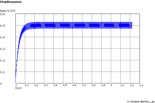
But it takes about 0.2s to reach the desired output.
> Not sure I understand the question
probably because I dont fully understand PWM and Ripple, but I appreciate your answer, and it does help me
I share your concern that slow pulsed lighting, whether pulsed by PWM or by Ripple, can have biological effects.
> FPWM is the PWM frequency, 244Hz for an extreme example
very helpful, and thanks for the charts too
how fast is the Ripple in a stock D4V2?
Which driver? 4-16 kHz PWM in the classic driver, 4 kHz “not sure how much ripple” in the linear driver.
Thank you for trying to help. Im a bit lost.