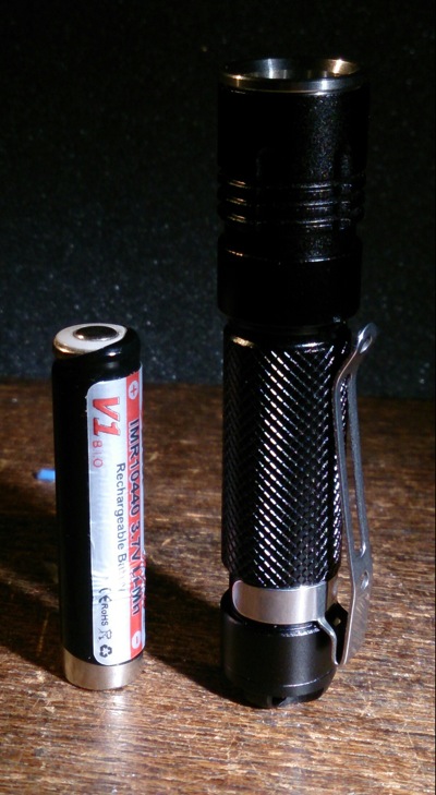
Not long ago I did a direct drive mod with this small AAA-size light. (details on the host can be found there, and in a thread about this light)

Everything very well connected, XM-L2 on copper, Efest 10440, it did over 500 lumens for 3 minutes (that is a significant part of total battery runtime already, 10 minutes at what I guess is 2+ amps). But, even tiny as the light is, 500 lumens is not always practical, especially since the beam pattern of such a small light with an xml favors close-up work (luxury problems, I know..  ), and 10 minutes total runtime on a battery gives it a limited use.
So, thanks to a few projects going on here at BLF, I was able to do a new mod on this light. It owes a lot to the work of Rufusbduck and Mattaus for their development of the tiny10 driver (all components of a nanjg105C on a tiny board), and the very persistent empirical work of comfychair for his testing of numerous types of FET's on just about everything, including on the nanjg105c driver. Richard (member RMM) was so kind to sell me some FET's cheap while he normally even doesn't ship overseas  .
.
The idea was to combine things, the tiny10 needs a lot of space to stack enough 7135-chips to get anywhere near 2A, and a FET works well with the nanjg105C. So I build up a tiny10 (well, actually a tiny12, Mattaus also made a 12mm version with a thicker minus-ring) with a FET on top:
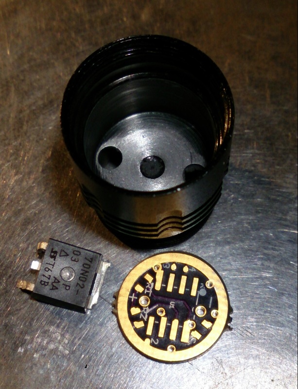
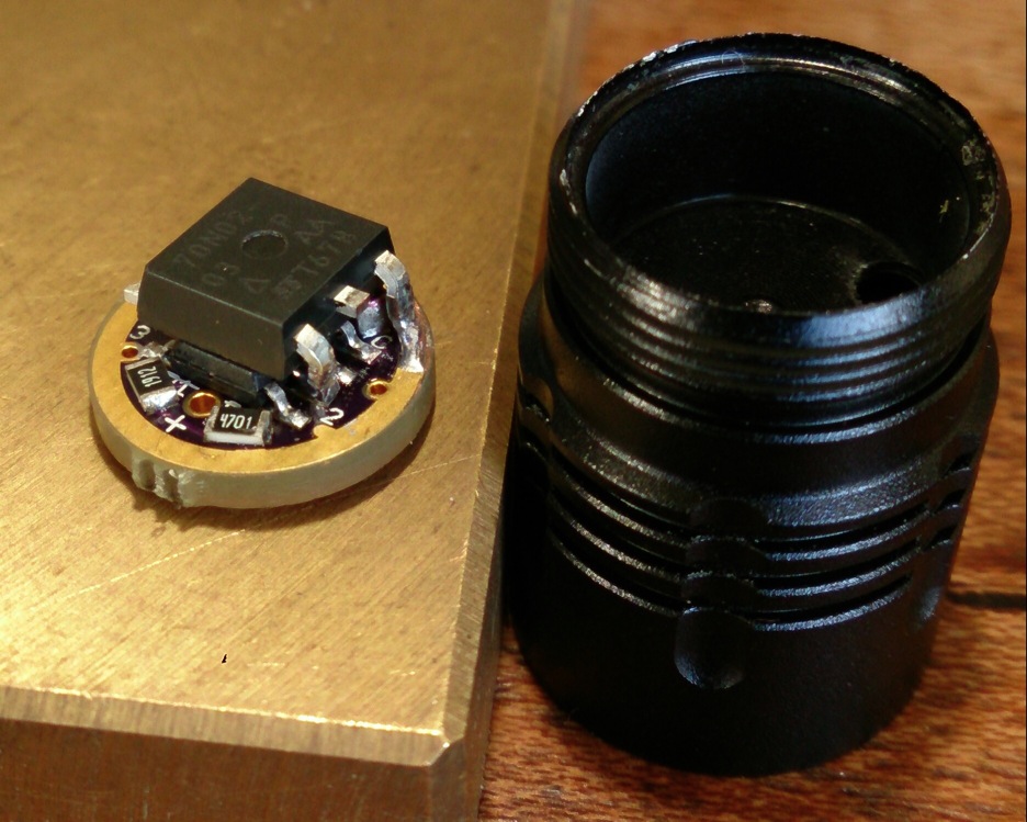
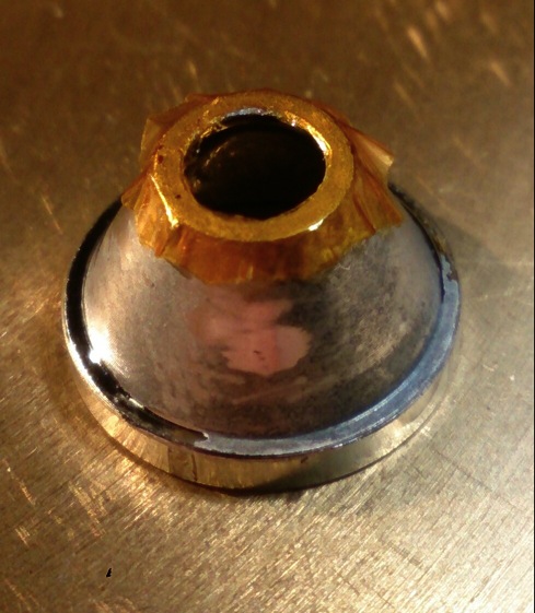
the tiny12 board, the FET, and the head of the LZZ-06 with the ano sanded off and flattened inside (1 hour fiddling with tiny pieces of sanding paper) for good contact with the to be used Sinkpad.
 (stereo picture)
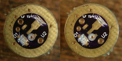
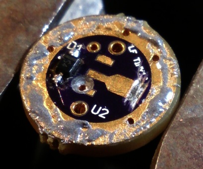
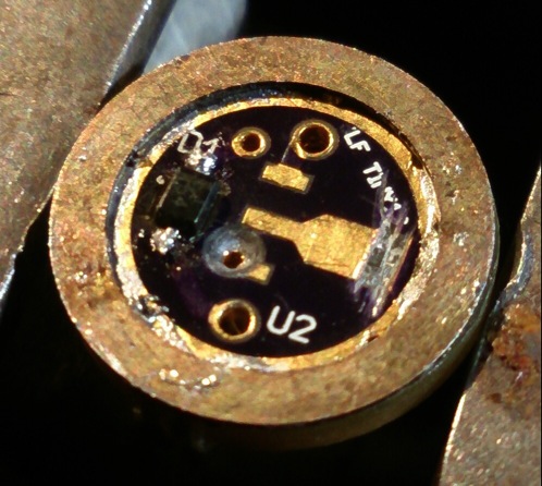
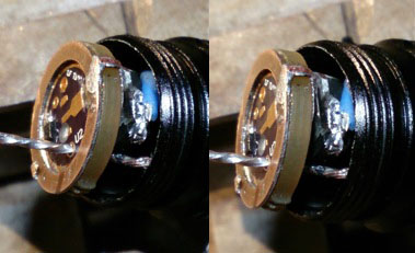
Preparation of the battery side of the board, the FET will be on the other side, this side must support the contact with the battery. The middle trace for the 7135 was cut through, the via to the MCU was disengaged by drilling it out a bit, the diode is going to be sinked a bit in a cut-out hole (scalpel work :glasses: ) . The led+ wire is going through the board and bend and soldered to the middle of the board and will serve as battery+ contact.
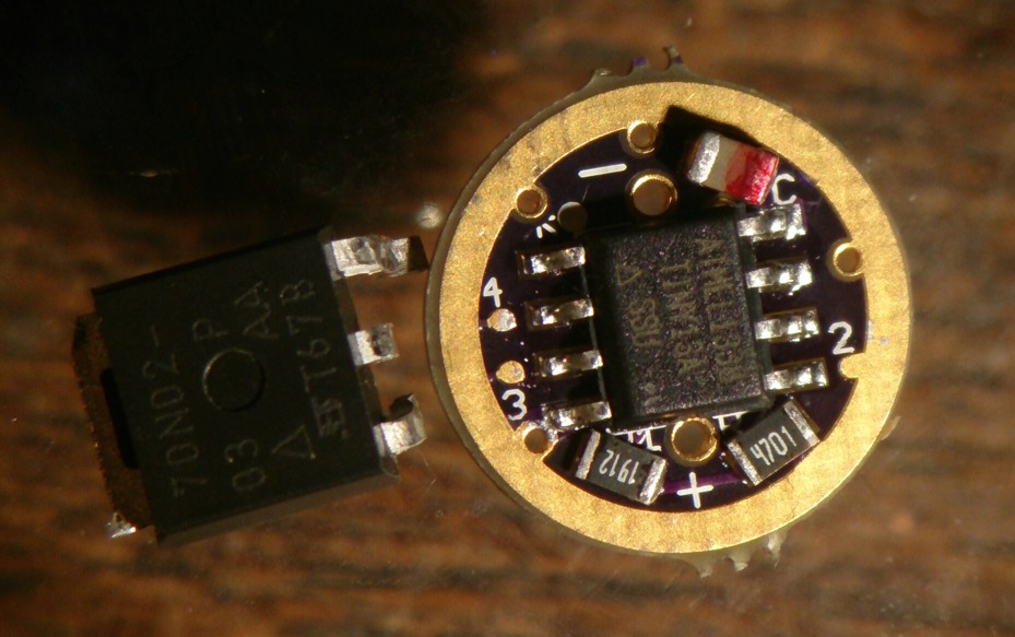
Now the components were reflowed on the board. the donor was a traditional Nanjg105C (in case you wonder: I labeled the +side of the capacitor with a red marker):
On the other side of the board, the diode was soldered into its new home ;-) :
 (stereo picture)
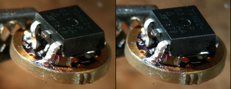
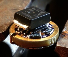
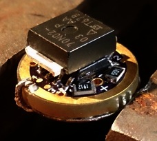
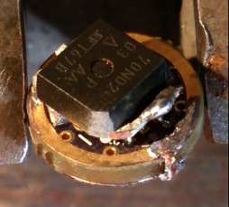
The FET was now placed on top of the MCU and the legs soldered to the correct pin of the MCU and to the ground (minus) ring. Some solder on the edge was filed away to make room for the rim on the flashlight head.
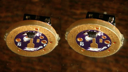
 (stereo picture)
As you can see there's just enough clearance for the capacitor, (there's even a tiny gap on top of the cap).
Here's the driver next to its destination. As you can see, it will almost completely fill the driver cavity. From this side you can also see that the led+ connection via still has clearance for the led- wire.
Now the driver could be tested, and it worked! I had an old XML on a Sinkpad, it did 2A on high , made a short video of that, (the kid chatting away is my son :-) ).

Next was getting rid of the blinking modes by closing solder bridge #3 . I thought it was a fine solder job, but the disco modes persisted, very annoying. Checked the soldering over and over again, it was really well done. Then it struck me: would it be?... I checked the low mode, and yes, 5 seconds later there was the flash for mode group change  , I used a different 105C donor than I thought. Nice enough, but it costed me half an hour.
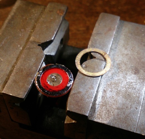
Some more work on the driver; on the stock driver is soldered a thin brass ring. Since a twisty causes some wear on the driver board I am going to re-use the ring. Also, two wires were soldered along the edge of the board because 12mm is a bit too small, the driver size should have been 13mm, and it is press-fit. I rely heavily on the quality of the anodisation for this; when it is damaged, there's electrical contact between driver minus and body, then the light will always be switched on. The original board had no driver traces touching the side of the flashlight head (which was nice and robust by the way)
 the grey stuff is solder paste:

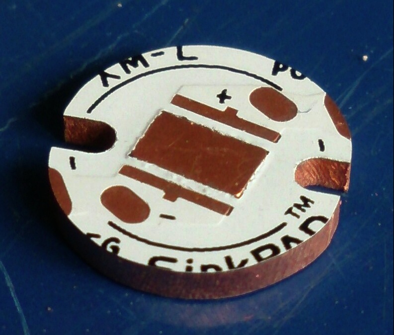
Ok, driver as good as finished, now the led board was sanded to fit the head (diameter ~13mm):
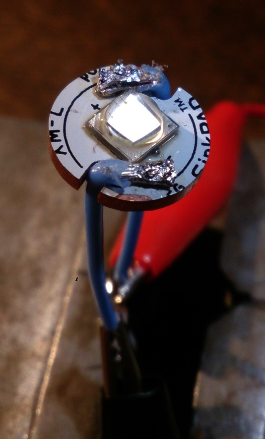
Led was reflowed, and led-wires were soldered. My 15W solder iron really struggles with soldering led wires on copper boards as you can see.
This mod could do with a bit thinner led wires by the way, they caused a lot of difficulties with the assembly. Because the aim was try to get as much as possible out of this flashlight I decided to go thick, but I doubt that thinner wires would make much difference.
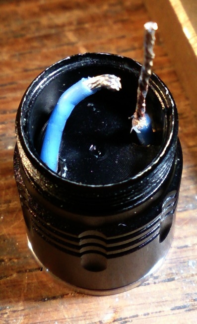
A little Arctic Silver was applied under the board and the board was pushed into the head. A nice feature of this host is that at this point you can close the entire front end of the flashlight head: reflector, lens, o-ring, and bezel can be screwed in tight, and the led board is fixed in place. Two layers of Kapton tape were sticked on the reflector to clear the solder blobs, the hole in the tape was made with a scalpel.
The led wires sticking out on the other side of the head were cut to size. the led- wire was bended to match the position of the FET-tab, the led+ wire was thinned (strands removed) and tinned with a little solder to be able to get them through the led+ via on the driver board.
Now the driver was slid over the led+ wire and with just a small hole left under the driver, the led- wire was soldered to the FET-tab.
Unfortunately the thick wire was in the way of the FET when the driver was pushed in. I had to unsolder the led- again and file some material off the FET (I needed not to be half as daring as comfychair ;-) )
Then after quite some more fumbling on the cubic mm (dutch saying  ) , the led wire was soldered to the FET-tab and the driver closed. Now the led+ was bended into position and soldered into the via:
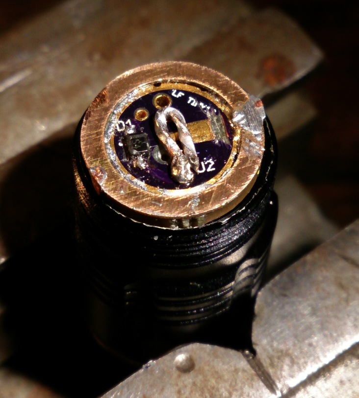
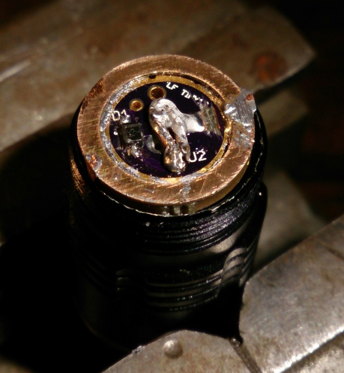
also soldered to the central (ex 7135-) pad:
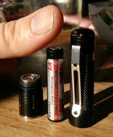
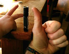
A picture with my thumb to get some perspective how small it all is:
The light could be tested for the first time now. And it appeared that the driver minus was indeed in electrical contact with the body of the light . so now I could luckily lift up the driver board a bit and file away the wires that I had soldered on the side of the board (no pictures of this frustrating bit of work  ). Then I pushed the board in the head again and luckily the short was gone. the driver board was not fixed in place as tight as planned, but it was tight enough to work well, it looked like it could handle the multiple twisting of the tail part against it.
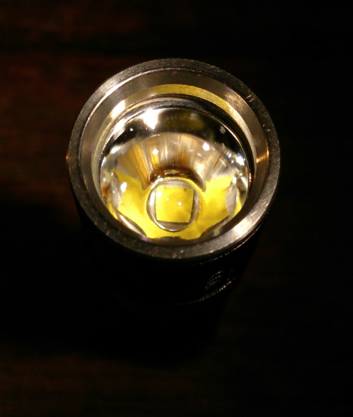
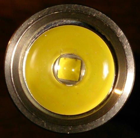
Glam pics:
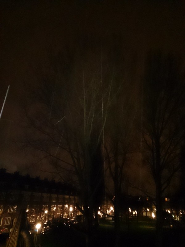
Beamshot at my trusty test tree @ 25 meter (it is raining today):
And now the output was tested. I did a runtime test for 5 minutes with my standard set-up, the light tailstanding next to the luxmeter, both facing the ceiling. I made a boring video of that, (it is still uploading now, I will insert it when it is done, EDIT: uploading is done), the lux-values should be multiplied by 1.22 to get OTF lumen values of the flashlight. At the end of the video there's my reference light (my SWM D40A).
http://www.youtube.com/embed/F9jnB1paMFs
The shrinkwrap of the battery did not like the 5 minute test very much  :
:
After the runtime test I let the light cool down (it was literally blistering hot after five minutes), and put a fresh Efest 10440 in the light to test if any damage was done to the light by the runtime abuse. It gave even better values (nothing spectacular, 15 lumen more), so no damage was done and this new battery was just a bit better than the one of the test.
The runtime test in a graph:
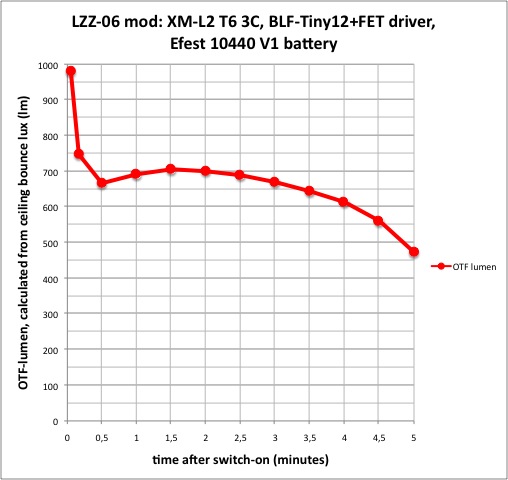
That is very nice, the output is even better than the true direct drive mod I did before: same shape of the curve, but close to 700 lumen for minutes now (980 lumen at 3 seconds, probably well over 1000 in the first second ). Reason is probably mainly the use of a T6 binned led instead of a T4 in the other mod. but I could also have been lucky with this particular led (or a bit unlucky with the 5D2 led of the other mod).
And on top of that, all the goodness of the Nanjg-driver: reverse polarity protection, low battery warning+shut-off, and best of all: low modes, in this case 5%, 30%, 100% (and because I used the wrong donor driver: hidden disco). This makes the light much much more useful.
LOL: the 5% low mode I measure at a steady 65 lumen, this is the output of a very ok unmodded AAA led flashlight .
EDIT24/3: I was curious about the lower modes because the 5%PWM low has an output that is not 5%, but 10% of the high output. On high the main output-drop happens within 10 seconds, so that drop has everything to do with sagging of the battery, at 5%PWM such a battery sag doesn't happen. So I did also a output/runtime test in medium and low mode. On medium the light still got too hot to hold after a few minutes, but not 'skinburning hot' like on high. Shortly after 9 minutes the low voltage warning of the driver kicked in (slow flashes of dim light: 13 lumen) Here also the shrinkwrap of the battery had become smaller. On low, the light was only luke-warm, low voltage warning after 77 minutes. Graph:
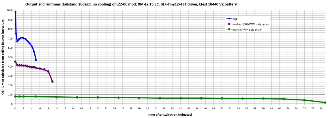
END EDIT24/3
I think this was my most labor-intensive mod sofar (but still nothing compared to the work that many others on BLF do for the hobby). As usual not everything went so smooth as the story&pictures suggest, but it was fun to use the stuff and knowledge that has recently been developed on BLF, fun to do the mod, and fun to report it. (and it is also quite nice that everytime a mod is done, I am left with a new fun flashlight :-) )
Thanks for reading!


")
