i have built several ZY-t13 with red xp-e’s and a resistor mods to get the amperage where it needs to be for the red xpe. during the testing of Vf on one of them i shorted the the test lead against the flashlight housing frying the driver.
i don’t know of or don’t trust any of the cheap buck drivers and wanted to retain the the side switch function on the ZY-t13. After doing the research i decided on the TaskLED Lflex driver(not cheap). this driver has a momentary switch for mode selection function,it has a user selectable current selection, user selectable UI, and user selectable TEMP protection settings, and many other features that i have not fully taken advantage of yet.
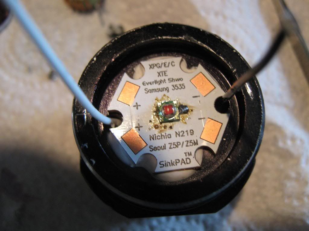
since this is a 2X18650 light and a red xp-e with Vf around 2.6-2.7v at 1.5A the driver will have to buck off alot of watts(heat) so a custom copper heatsink was in order. the emitter selected is an XP-E red P3 bin flowed to copper SinkPad mounted in the light body with AAepoxy on edges of MCPCB and AS5 grease in the center. there is very little room between the MCPCB and reflector when the light head is screwed to the body so screwing down the star wasn’t really an option for this build.
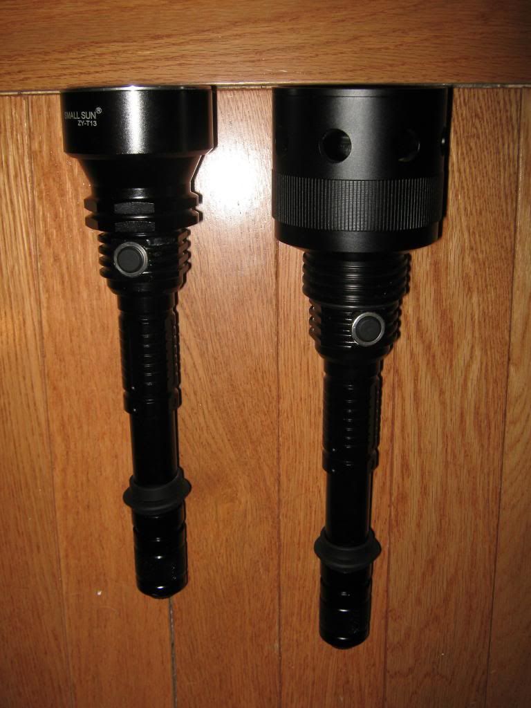
original small sun ZY-T13 and ZY-T13 with crelant aspheric head(notice 1.5 inX.137 oring between aspheric head and light body)
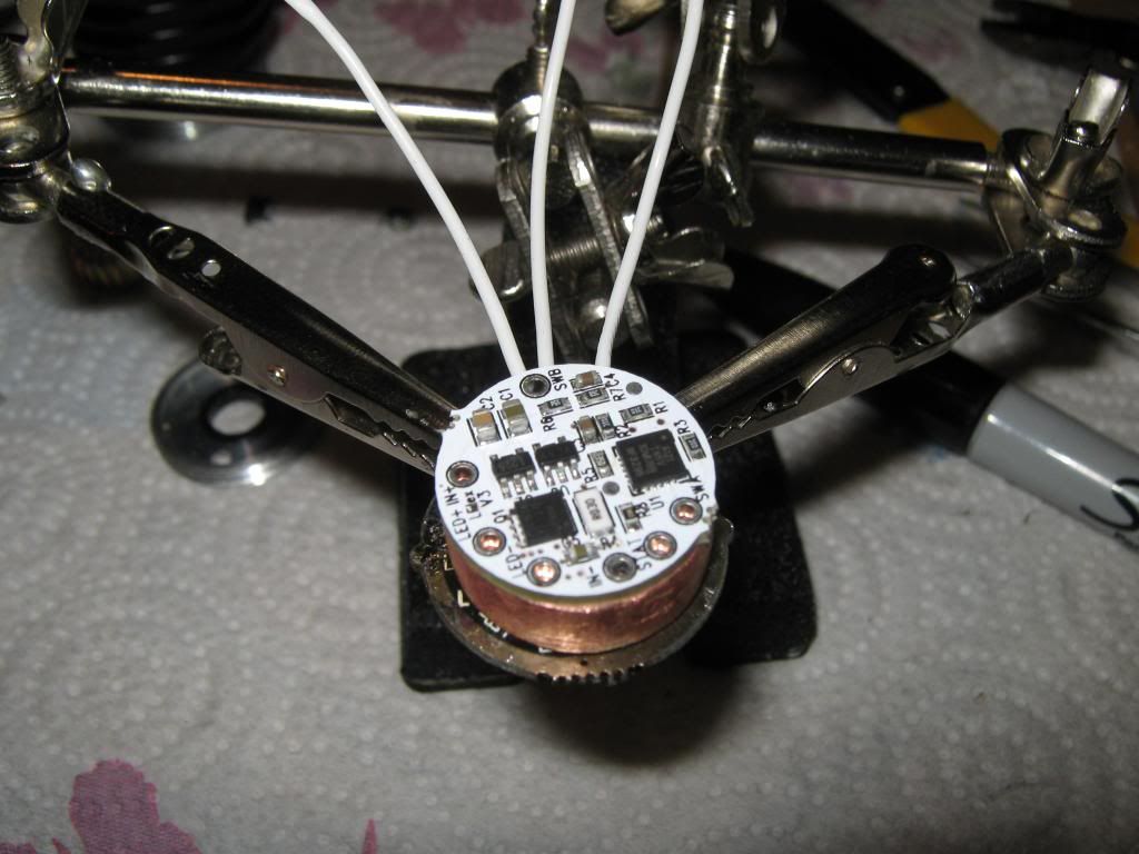
driver/emitter housing, Lflex driver,original driver with original momentary switch and battery+ contact spring, copper heatsink and driver retaining ring.
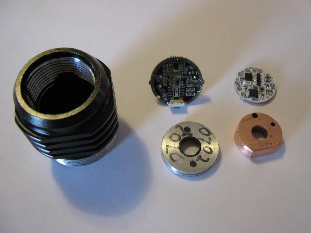
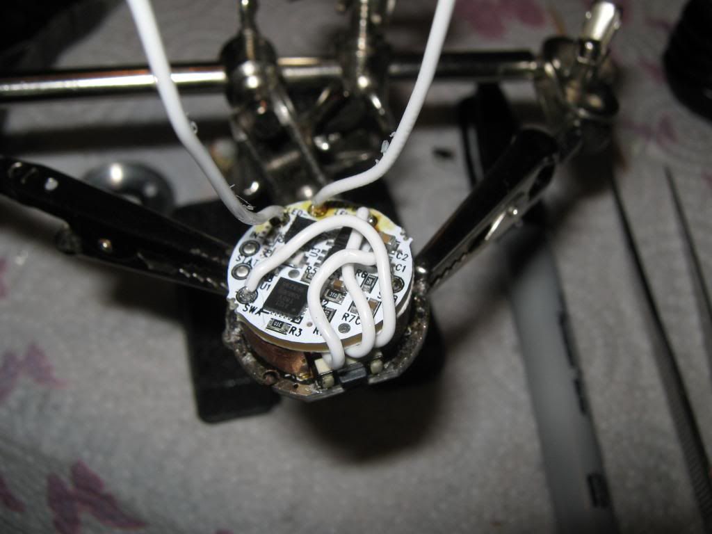
original driver with all components removed and pigtail wires for momentary switch and driver+ soldered on
top view copper heatsink, heatsink made by using one inch holesaw and .250 in thick copper plate. notches hand filed.
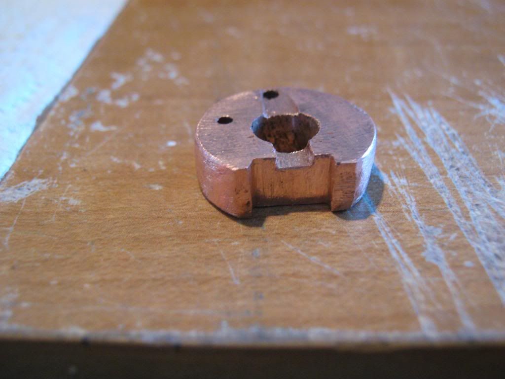
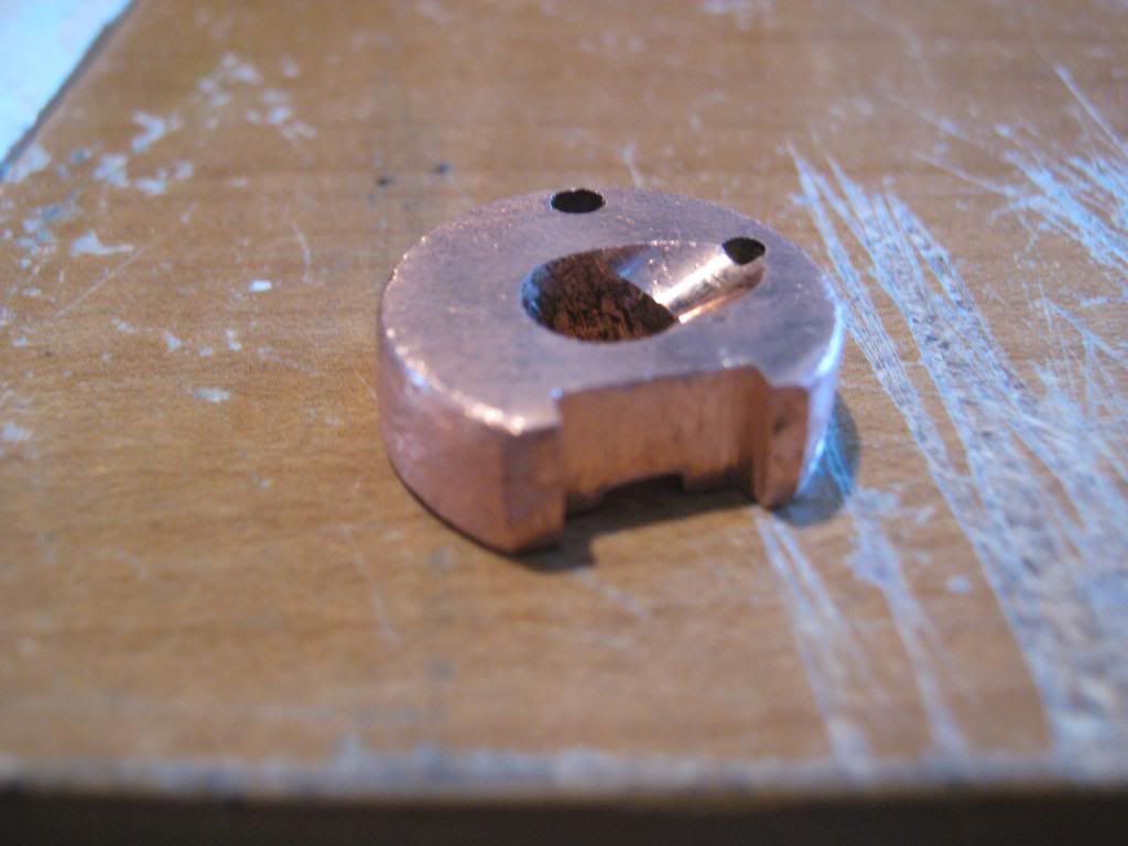
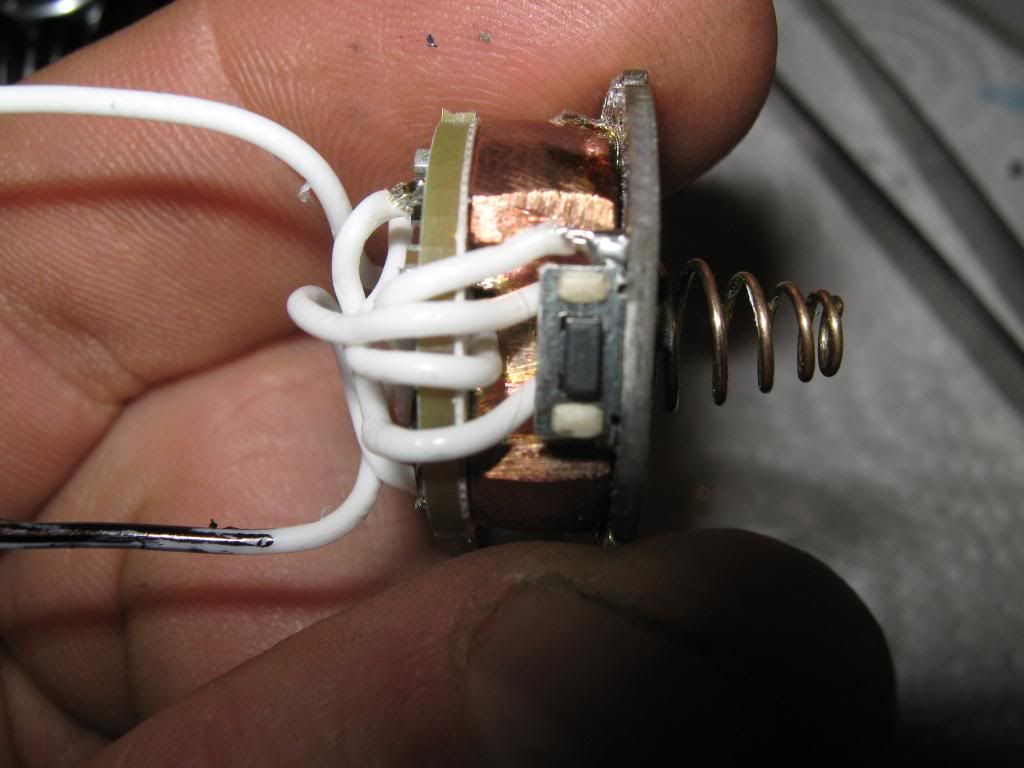
bottom view with notch for +battery wire clearance.
driver on top of heat sink mock up, notice notch for +battery wire pass through.
mock up of driver, heatsink,contact board
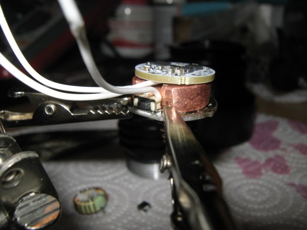
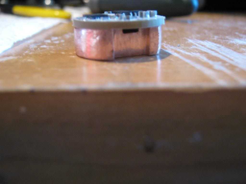
copper heatsink soldered to contact board supplying thermal pathway to light body
driver attached to heatsink with thermal pad supplied by Taskled
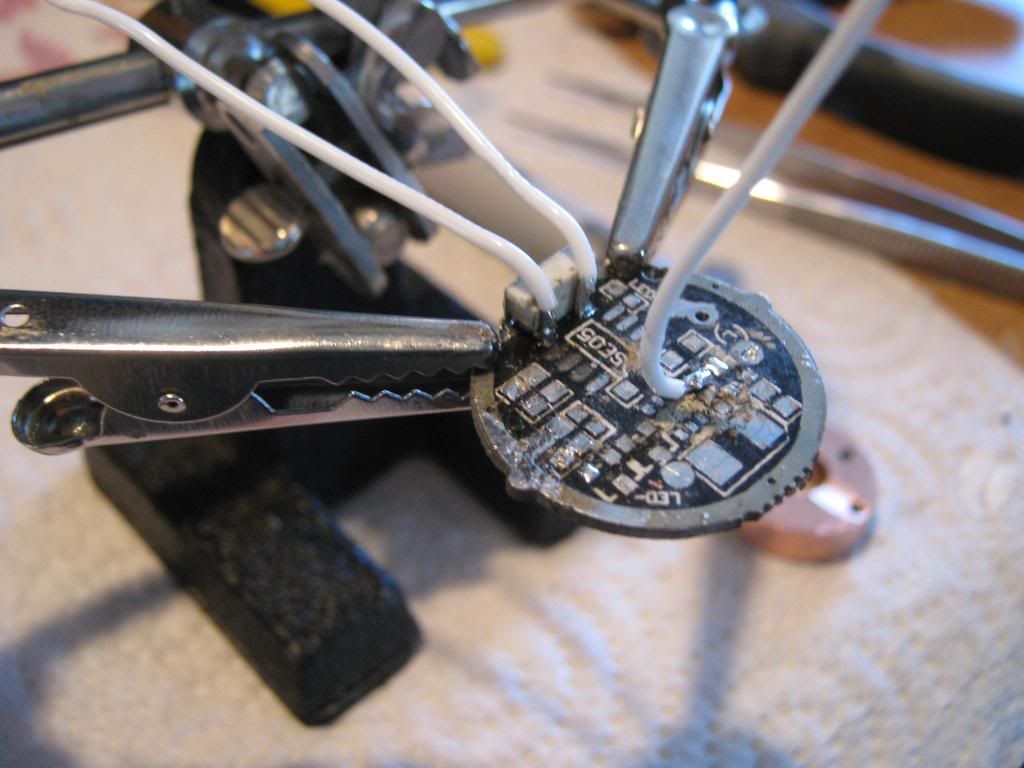
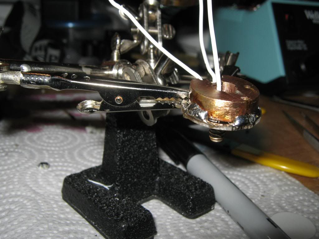
wiring completed except for driver-
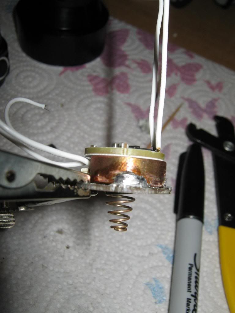
completed driver assembly
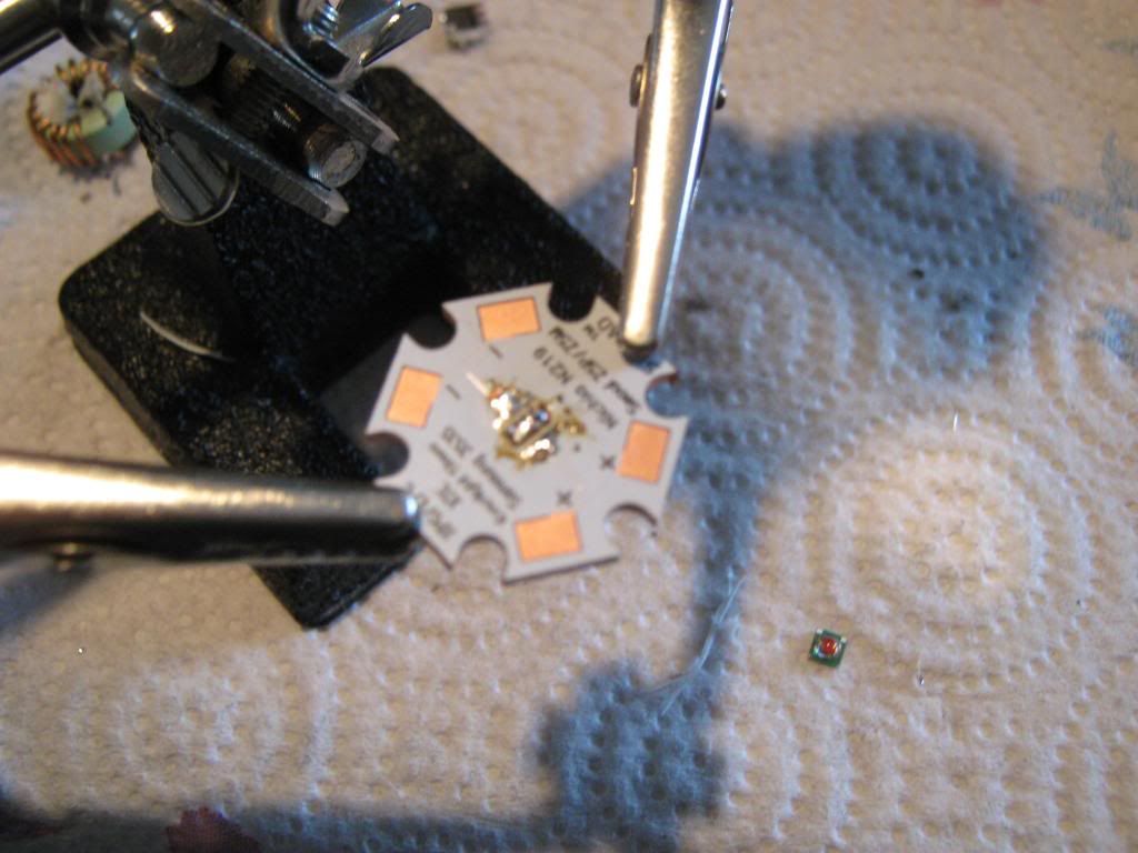
red xp-e p3 and copper sinkpad
copper sinkpad attached to housing with AA epoxy on edges and AS5 in center and pressure applied til epoxy cure
the results that follow are only relative to my own measuring methods and equipment. my lux meter is a DR. meter 200,000 lux( its reads about 10% less than a friend of mines cheap DX meter) and my DMM is craftsman made by ???
lux readings taken at 3m then corrected to lux@1M
results
with driver set to 1.5A
reflector
lux @ 3M 2950
lux @ 1M 26.5Kcd
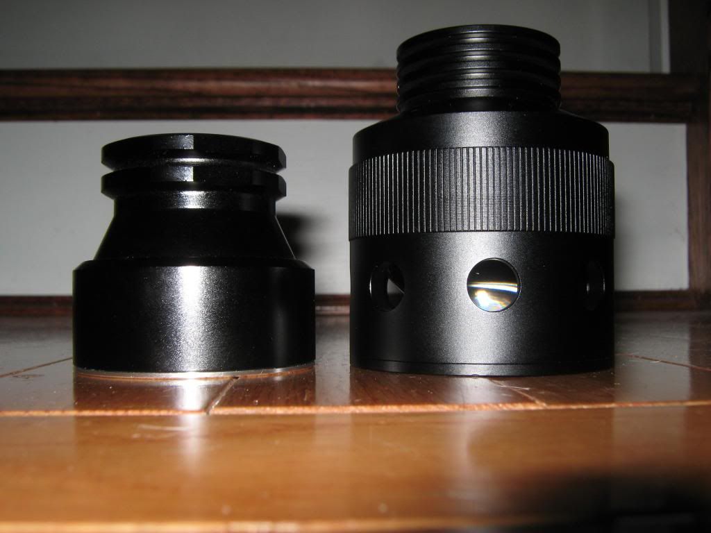
aspheric w/front lens
lux @ 3M 7120
lux @ 1M 64kcd
aspheric w/o front lens
lux @ 3M 7620
lux @ 1M 68.5Kcd
2.8v @ emitter
1.48A @ emitter
i have no idea what i’m doing when it comes to photography and taking beamshots.
i’ll do my best to describe what i did. heres as much information as possible so the beamshot analysts may critique my methods and results.my camera is a canon powershot A470 auto everything. i have no idea what settings the thing was at when photos were snapped.
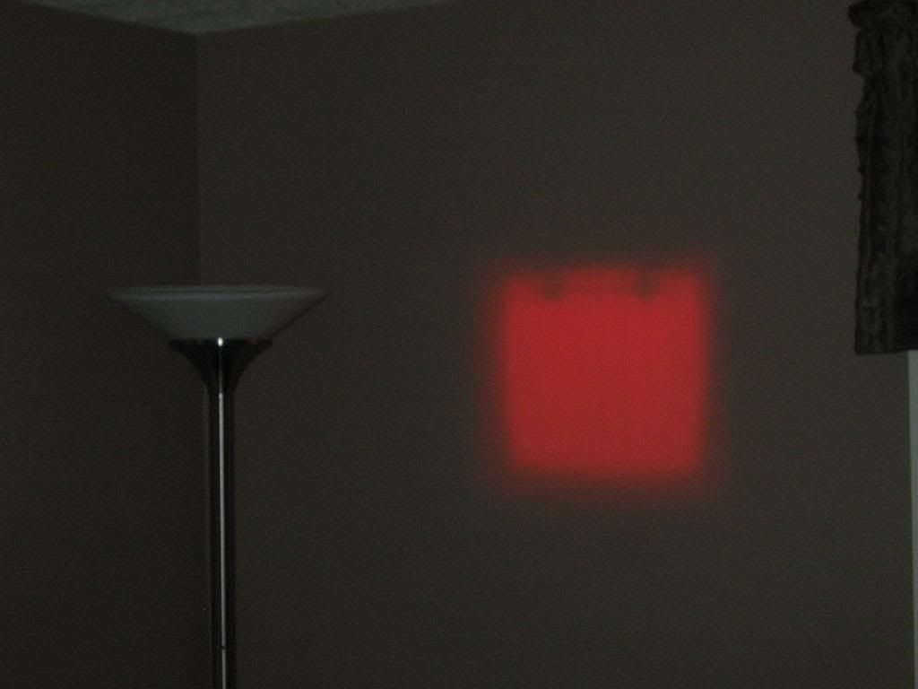
in this pic the light was set 37 feet from the wall. i stood approx 6-8 feet from the wall to snap the shot.it is daylight but not sunny and the shades are drawn in the room. i used macro and no flash. my walls are painted medium brown. in this pic, correct me if i’m wrong but there is some for lack of a better term “flashback” causing the photo to look brighter than it actually is.
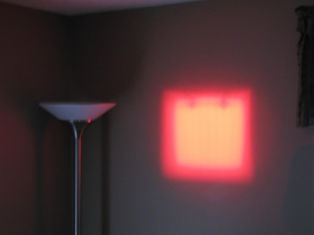
in this pic i used macro with flash. this is a good representation of the color as seen by the naked eye, however this pic is not a good representation of how bright it is. in my opinion the brightness as seen by the naked eye is somewhere in between the two pics.