You can check whether it’s the chips or the mcu by jumpering from the output side of your 200 ohm resistor to the Vdd pin of the closest 7135. This will lock all the chips on high bypassing the processor but still limiting the input voltage to the Vdd pins. If you get full current then the 7135’s are ok. If not then you can measure the voltage across your Zener and the resistance of the 200R. Don’t know how to directly test the processor.
Great Mod, DBC. And sure the beam shots did well.
I’ll definitely check into it. Would be nice to be able to save the board and put it back in for regulation and modes.
Went out last night before bedtime with the DD K3 and the S2200. When I first modded the K3 it was fairly obvious that it was brighter than the S2200. But now it doesn’t appear brighter at all and even seems to have a warmer tint. So when I got back in the house I checked battery V fully expecting to see the cells low. Got 4.02V on each and ran an amperage test that showed it still pulling 6.34A, considerably MORE than the 4.40A of the original mod!!
I’m not understanding this. ![]() The only thing I know that would cause a tint change is from when the light engine fell off the work surface. The dome shows that silvery telltale sign of separation from the die on about a third of one side. Don’t know if that’d change the tint or the output but that’s the only thing it could be, as far as I know.
The only thing I know that would cause a tint change is from when the light engine fell off the work surface. The dome shows that silvery telltale sign of separation from the die on about a third of one side. Don’t know if that’d change the tint or the output but that’s the only thing it could be, as far as I know.
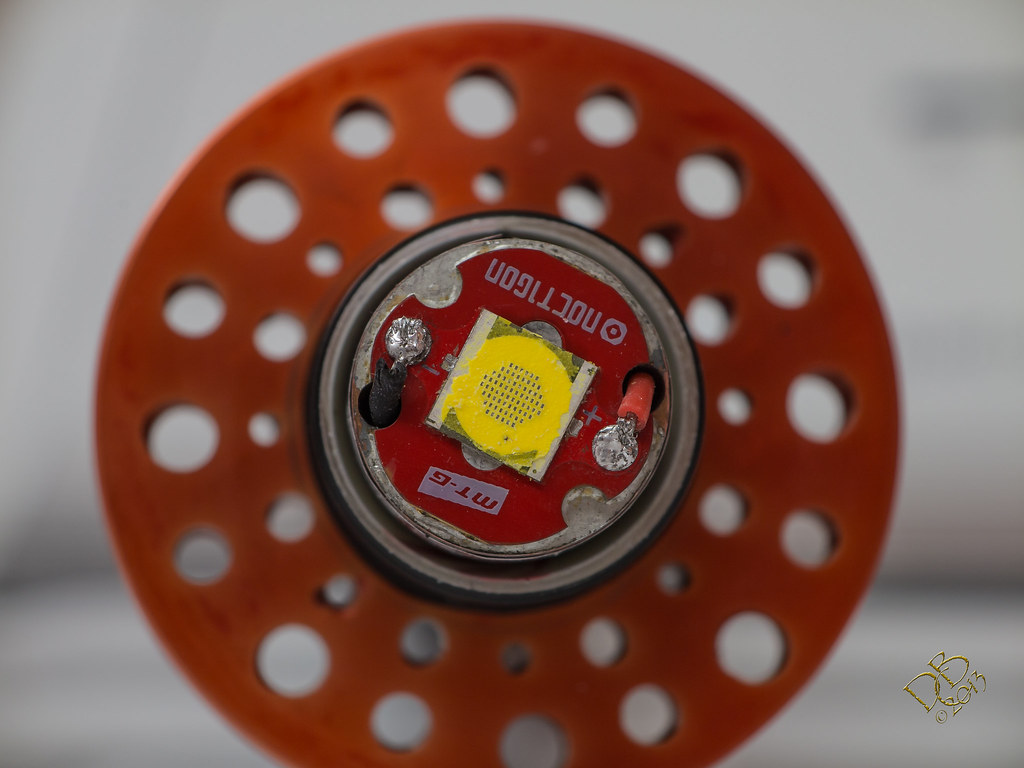
This is the brand new MT-G2 from Intl-Outdoor that I got along with the Noctigon pads.
I’ll hook up the pad/emitter from the original light, the one on the 32mm board, and test the driver. See if I can figure out why the high was giving erratic performance. I was careful getting the driver out, but I did have to pry on it with a very small screwdriver and did some very small damage to the edge of the board at the outer wide ground ring to a chip. Guess we’ll see.
Check the voltage at MCU pin #8, compare to what you measured there when it was first built... you did measure that to make sure the voltage was being handled properly by the zener, right? :X
I certainly didn’t ![]()
Will the MCU actually work without exploding at first switch on without the zener working?
That depends on if the voltage is too high or too low. It'll still work with full battery voltage on it... for a while. Then it'll start acting weird. Driver will get hot, start flickering, do all kinds of weirdness. It won't explode the instant it gets more than the datasheet's listed 6v max. The 7135s aren't happy with high voltage on the Vdd pins, I don't think the weirdness comes from the MCU itself.
If it's too low (under 3v) the MCU will think the batteries are dead and give you the low voltage warning/shutdown, depending on what code it's running.
Hmmm…….I guess I can either remove my driver and measure the voltage, or just give it a good ops chk.
I kinda got excited that it was done and fired it up, since it was working I did the unthinkable and assumed. ![]()
Here’s a shot of the damaged MT-G2 from it’s little excursion when it tried to run away from home

Here’s my very first anodizing bath! A 4” 6061 tube inside a folgers coffee can. Fired it up with a 12V SLA battery and it wasn’t enough, so I wired 2 in series and got 3A flowing through the acid, this time it got a nice anodization and took the dye beautifully! I hate learning curves! Well, up until it works out, then I forget about it. lol

Fire in the hole! Or holes in the fire, or hey watch out this part get’s hot! Whatever…

Not bad for a substitute method, huh? No battery acid was harmed in the colorizing of this aluminum. Pool PHdown dry acid did the trick!
There must’ve been some impurities embedded in this piece of aluminum from another day, got a couple of nice little pits eaten into it. But overall, and considering it took a second attempt, I’m pretty pleased with the result. Would have liked the deeper red-orange like it came out of the bath, but the boiling session lightened it to this which is still just fine. A custom mix of Scarlet and Sunshine Orange. ![]()

Now you’re gonna have to post temp graphs and massive current performance curves.
I don’t do pie charts, cake is so much better. ![]()
I wish I knew how to make those charts and graphs, don’t have the tech for it. Wish I could just layout a perfect circle, that’s difficult enough by itself. While I’m wishing, I wish I had a drill press that’d drill a true hole.
My drill press is SO bad, I did all this with my cordless Makita…used the drill press to cut out the initial circle with a 2 5/8” Metal cutting hole saw from Lenox, then ixnayed the drill press due to it’s issues.
Printed out my Photoshop drawn pattern, used a spring loaded punch to mark centers (free hand) and drilled everything with the pattern taped over the disc. Didn’t want a bunch of holes in my sheet of 3/4” plywood backing, so I used issues from a stack of Rangefinder magazines. ![]()
I don't even try to drill a finished hole with my drill press anymore, I'll drill a starter hole and then switch to an end mill and a little fixture I made, U-shaped round wire guide to let me spin the part in an actually concentric circle while cutting.
Has anybody taken the chance on one of those '9-in-1' or whatever hobby mill/lathe/drill press things? I think they're less than $200, which doesn't really inspire confidence...
I did some testing and got some numbers, but to me that’s all they are…numbers. They don’t necessarily add up to or mean anything.
Here’s how I set it up

And here’s the numbers:
From the Zener, 5.98V on Lo
5.65V on Med
5.35V on Hi
From the LED, 6.35Vf on Hi
5.35Vf on Med
4.94Vf on Lo
And from the Vdd pin, (far right, facing the 3 legs)
4.81V on Hi
1.60V on Med
.21V on Lo
And with my 12Ga copper short wires at the emitter
4.03A on Hi
1.12A on Med
.08A on Lo
So what does this all mean? Obviously, the driver is functioning with all 3 modes when out of the copper pill, which tells me I had something shorted out in the installation. It was a force fit, and a bugger to get out of there!
I modded my S2200 today by stacking 3 1R00 resistors on top of 3 of 4 220 resistors already there. Quite a difference out in the field! Amperage bumped from 2.10A to 2.53A at the tail, deceptive as there’s quite a bit more light and the heat gets started noticeably faster as well.
Here’s an animated GIF depicting the S2200 in May, stock, and tonight, modded.
And here’s how the K3 in direct drive stacks up against it
S2200

K3

Neither had exactly fresh batteries as I’d gone for a walk a bit earlier. The K3 is running Panasonic NCR18650PDs at 6.32A (reading taken after the pics) Of course, the K3 still can’t throw as far as the bigger deeper reflector that the S2200 utilizes, but it’s putting more light in a broader area and does a remarkable job considering it’s appreciably smaller form factor.
As usual, the red oil barrel is 97 yds away. Settings on the G1X camera are still ISO1600 F/5.8 at 1/2 second exposure. In the animated GIF, the original shot back in may was as ISO800 F/2.8 at 1/8 second exposure, so for this animation I used the same settings for that one shot. And, as usual, the original picture straight out of the camera is uploaded on Flickr for High Resolution details.
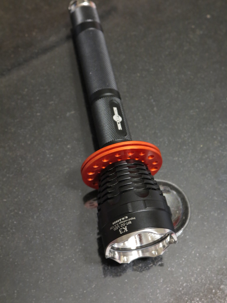
I need to learn the art of leaving well enough alone. But I’ll do that another day. ![]() Today, bored, I got to looking at the MT-G2 in this K3. This is the one I ordered from Intl-Outdoor along with the Noctigon pcb it’s sitting on. When I was working on it’s assembly and it was quite hot, I dropped it. And this did some damage to the connection of the die and dome. So, with the 45mm TIR optic that fits into the K3 head looming large on the mod list, I de-domed the MT-G2 emitter and put the TIR in the K3.
Today, bored, I got to looking at the MT-G2 in this K3. This is the one I ordered from Intl-Outdoor along with the Noctigon pcb it’s sitting on. When I was working on it’s assembly and it was quite hot, I dropped it. And this did some damage to the connection of the die and dome. So, with the 45mm TIR optic that fits into the K3 head looming large on the mod list, I de-domed the MT-G2 emitter and put the TIR in the K3. ![]()
And yes, it got cooler instead of warmer. And no, the phosphor did not come off with the dome. I have no idea how it came off so clean, but all the tiny little rectangles look like brass, shining inside this sea of yellow/green phosphor. And no, the TIR is not made for this size emitter…it’s made for an XM-L die. But with the emitter de-domed the area of rectangles fits under the collection tube on the TIR so it works.
Yeah yeah, pics or it didn’t happen. Well, I’d post pics if I knew how to take pictures. Or if I had a decent camera. But, oh wait, I DO know how to take pics! And I have 3 decent cameras! So I guess y’all are in luck if you’re interested in seeing what I did to this K3 from Solarforce…this time!
There is definitely a tight hot-spot with a pretty tight corona and some spill. There are also some rings. Oh well! Can’t have everything!


This is pretty much what it looks like, but not as bright. I wanted the beam to show and it’s just intense so difficult to capture with the camera in a setting this close. About 14’ from the fireplace. Tint is pretty much what you see with your eyes. Blueish, almost a bit of lavender. So I’ve lost my pretty off-white tint. Waaa.

Shot at 1 square foot white Styrofoam ceiling tiles, from approx. 9’ distance. Nice tight hot spot. Shot severely underexposed to show the hot spot.

The de-domed MT-G2 on a copper Noctigon on a 7/8” x 1” slab of copper, in the light.
And a cropped close-up to show the die better.

Can’t wait for dark to see how it compares outside. ![]() It’s definitely different now! lol
It’s definitely different now! lol
Nice experiment. How long until its dark?
About 4 hours. ![]()
I ran the light for about 2 minutes in direct drive with fresh Panny PDs. Then I cut most of the dome off with an XActo knife. Then I ran it some more and cut it closer. Then did it again til the dome was only about 1/32” thick. Then I ran it some more and used tweezers to pull the remaining silicone off the emitter. Had to run it a couple more times picking the pieces off but it seemed pretty tough and I could actually scrape the die lightly to remove bits and pieces. Surprised me. The absence of wires made it a breeze. ![]()
You definitely did lose the phosphor, the top surface of the dies wouldn't be exposed otherwise. The side spill still excites the remaining phosphor enough to make it still marginally white light output instead of royal blue, and that blue from the dies plus the shite from the phosphor is what explains the tint shift. Originally the entire square base was covered with a layer of phosphor (not like XML/XPG, where only the die is coated).
Well, the silicone came off clear with no yellow phosphor on it. Or none that I could see. Didn’t spend a lot of time checking it out. But of course, looking at the other 2 I have on hand shows the phosphor covering the entire die. Might should have left it with that thin covering of silicone, I had it pretty smooth using a brand new XActo blade. Oh well! ![]() Looks pretty cool the way it turned out, for whatever that’s worth! lol
Looks pretty cool the way it turned out, for whatever that’s worth! lol
I looked at both this one and my S2200 through the welders glass and the rectangular “dies” don’t actually light up, the phosphor between them does. Also checked out the one that’s open and mounted on my bus bar. But only in that section between them and around them, not the entire phosphor surface.
Welding lens blocks the blue, you're only seeing the light emitted by the glowing phosphor which is where the white light comes from, the top surface of the dies is emitting royal blue.