This is my first time participating in this contest after some people suggested I should enter my creation for this year’s OL contest, and as I haven’t really been on BLF much I derped and ended up making a separate post instead of entering immediately. This post will reuse images as well as add some more with better descriptions and elaborate more on how I built my light.
The inspiration to mod this started from a few posts on /r/flashlight showing off the light, and I thought it would be a fun project to start. I did not plan this much in advance, but pretty much just looked around at what spare parts I had - a spare XHP70.3 HI on an MCPCB and an M3-C driver. Upon taking the light apart I realised it was possible to fit 2x26650 cells in series as opposed to the originally planned 26800 with a 3D printed spacer, so I changed my driver choice to the 6V8A L6 buck driver. This also gave me an opportunity to add a 58mm lens from Convoy to my order as the stock polycarbonate one had to be removed destructivel (more on that later). I did not have access to many tools so milled or turned components would be near impossible or very tricky.
Starting with the disassembly:
Unfortuntely I forgot to take photos of the light before I modded it, so disassembly may be harder to understand. This light was realtively simple in construction - a thin-walled aluminium tube with the head drawn out to fit the reflector and machined down with a small lip. The switch, LED, and reflector were simply sandwiched between the battery and front lens, and a small lip that was machined on the inside of the bezel held the lens in. To remove the switch and spacer the white switch ring must be levered out with a small screwdriver, exposing 2 small philips heads attaching the outer black moulded plastic to the spacer - I chose to re-use the moulded plastic as it would make it look closer to the original light. After the plastic is removed the switch and spacer will simply slide out the head, and I chose to not reuse them as I doubt that switch would be capable of the 8A+ the driver would consume. (This post by someone else on reddit shows a much less invasive mod and how little of the original light could be re-used for what I had planned)
Now for the mods:
With how much power the XHP70.3 would have to dissipate a proper pill/shelf would have to be used. I measured the inside diameter of the tube as well as taking into account how much space would have to be left for an optic, and chose to use 38mm brass round stock which would have to be machined down. The optic I chose was the largest TIR that would fit in the head and could be mounted easily, the LEDiL Carmen 50 - I was able to order this from RS components and pick it up the next working day (yay click and collect)
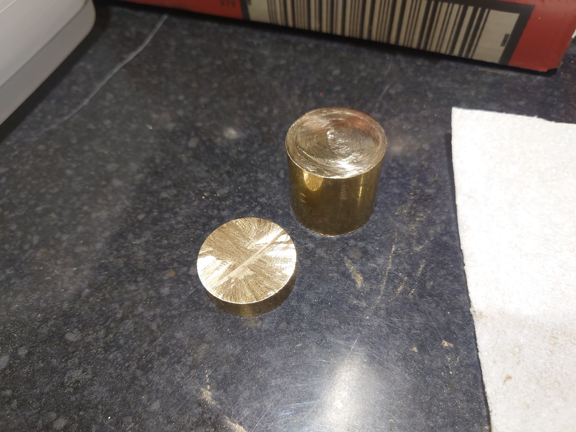
This is the chunk of brass that arrived a few days later:
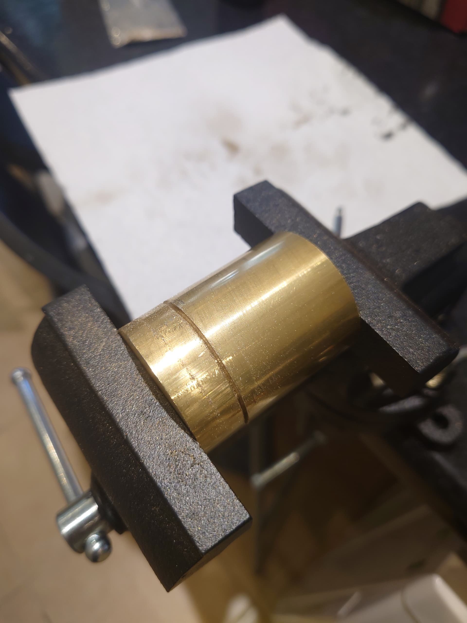
A whole afternoon with a junior hacksaw and elbow grease resulted in this:
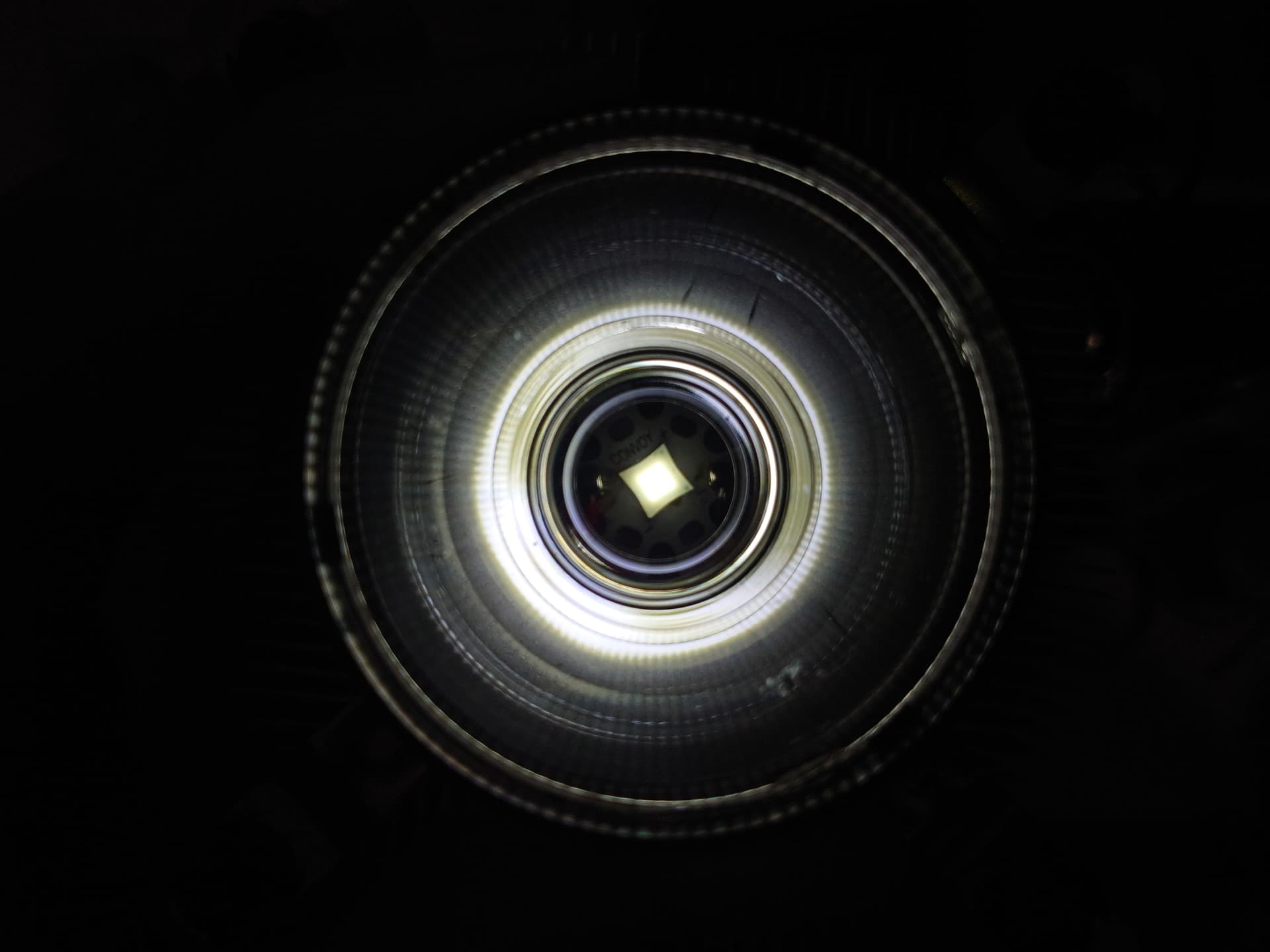
And a test fit with the optic over an MCPCB mounted to an Intel cooler:
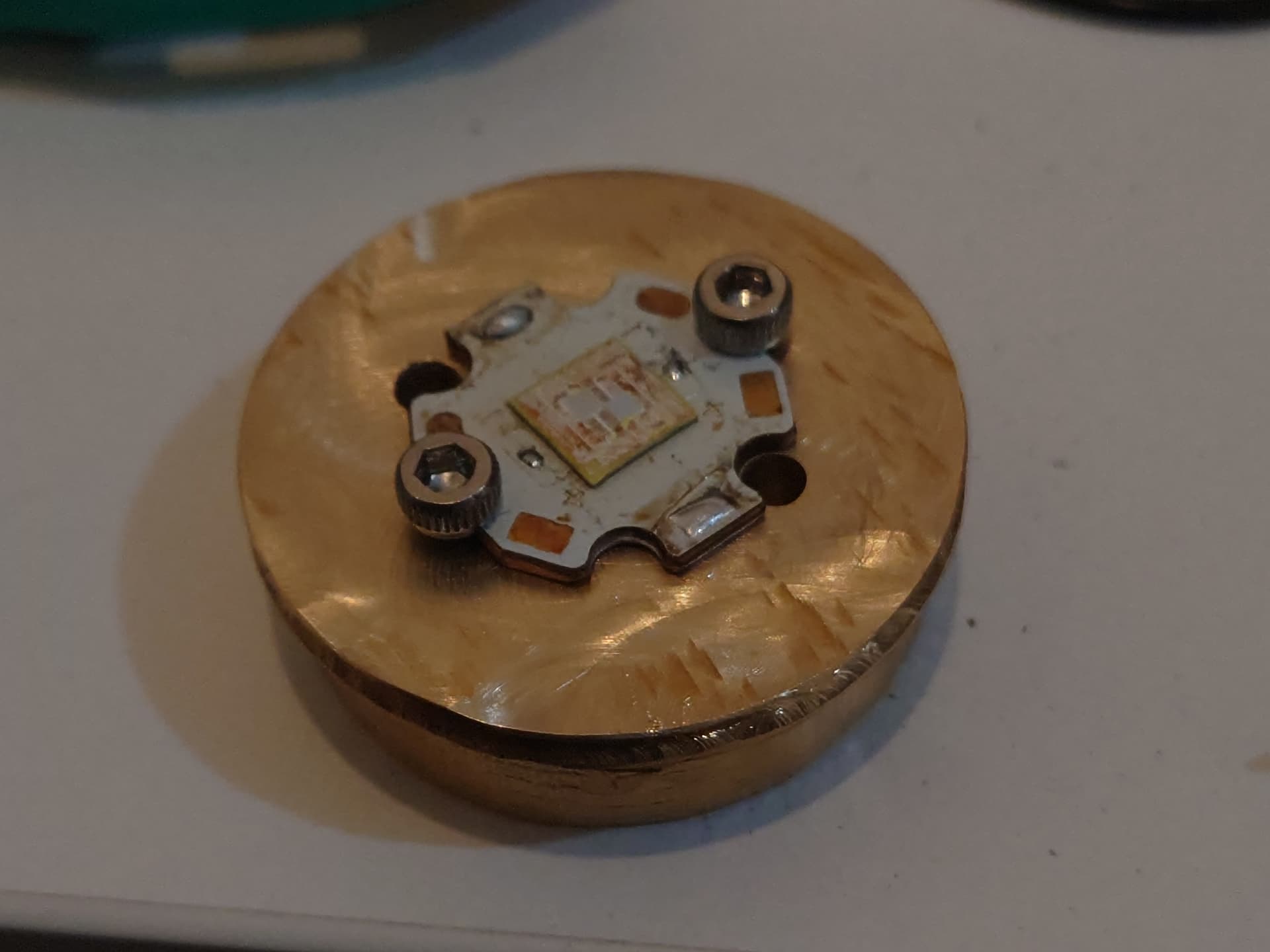
After I had cut down the round stock to the correct size, it was time for some manual machining with a knock-off dremel and rotary burr. I used some calipers to scribe some rough guides for the MCPCB mounting holes and to grind down to (it had to be arond 32mm for most of the height but had to have some material left to prevent it from falling through the tube). The resultant product was a weirdly shaped chunk of brass that fit rather snugly in the light.
Using the torch body to check what parts needed to be ground down more for the pill to be flush:
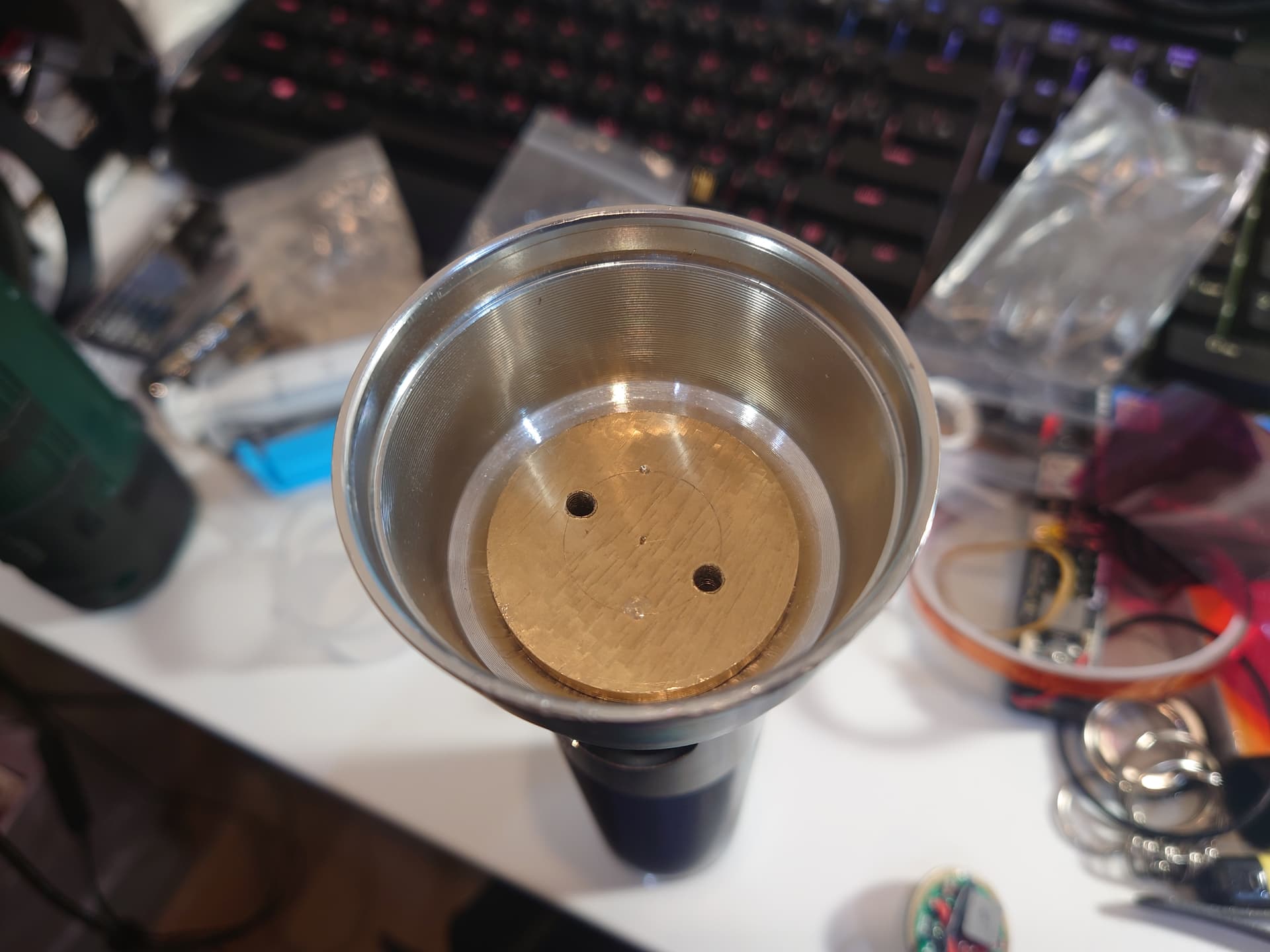
Two pairs of holes were drilled: one 3mm pair for the wires to go through, and one 2.5mm pair that was tapped with an M3 thread. I learnt the hard way that freehand tapping in a soft material such as brass results in a self-stripping tap so I actually drilled both sets of holes to 2.5mm to allow for a single screw-up.
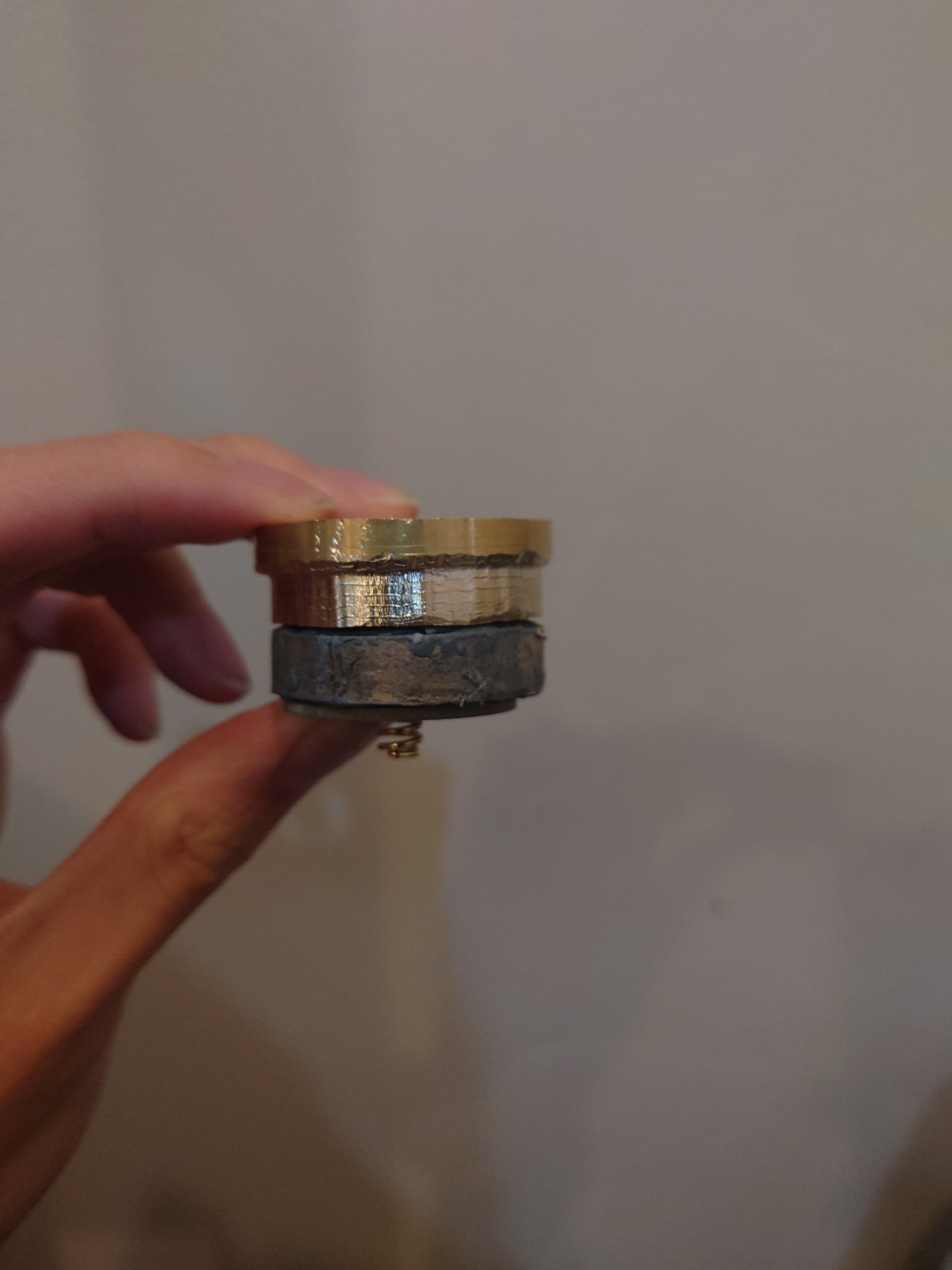
Using some metal epoxy, I created a spacer for the driver, as I wanted the most thermal mass available for the LED and did not fancy manually carving out a driver compartment out of brass. Due to the epoxy being somewhat thermally conductive it wouldn’t affect thermal regulation that much but as it was electrically insulating another solution was needed to connect the driver to the tail switch.
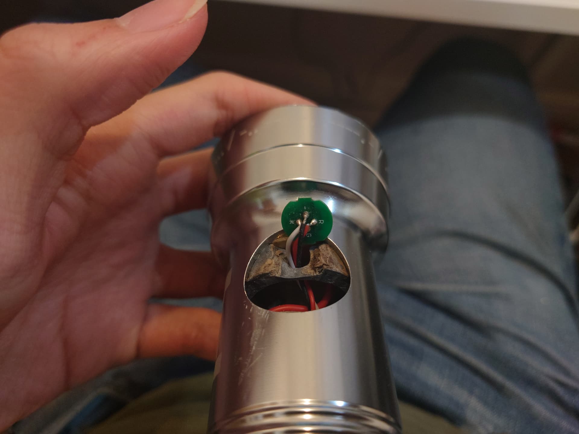
A hole was also made in the side of the space for the e-switch wires to run through. Annoyingly the driver consists of an e-switch to change modes and a tailswitch for power, but it was probably a better idea since it’s a relatively powerful driver.
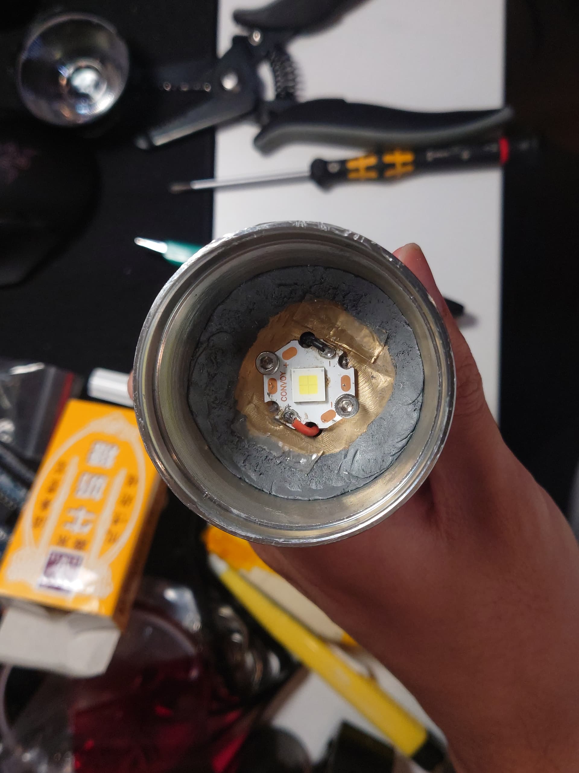
Once I was happy with how everything fit together, I used some more metal epoxy to attach the pill permanatly to the body to give it a chance to dissipating the up to 48W input power to the LED. The epoxy cured very quickly and was extremely sticky so it was a challenge to get it to stick to the metal instead of my fingers.
While the epoxy was curing, I could prep the optic to be mounted over the LED. The Carmen series of optics from LEDiL were designed to be mounted to COB arrays so some bodging was needed for it to fit over my LED. A generous amount of UV resin was dripped on the optic frame and cured - the excess would be filed down to line up the optic and attach with some VHB tape.
The holder with a large blob of resin on each leg:
I also added some glow resin made of phosphorescent powder mixed with some UV resin to the holder, which would shine through the TIR:
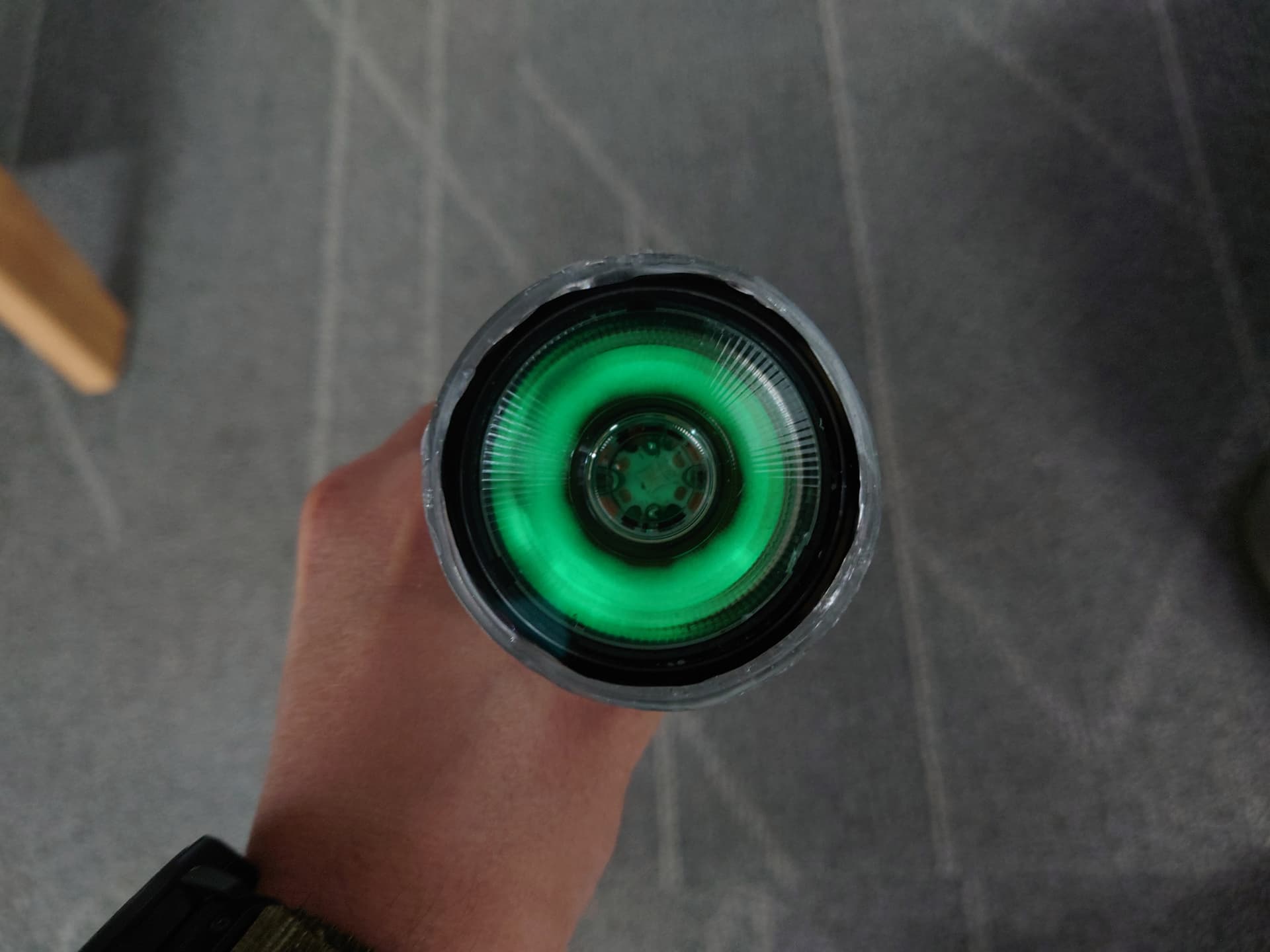
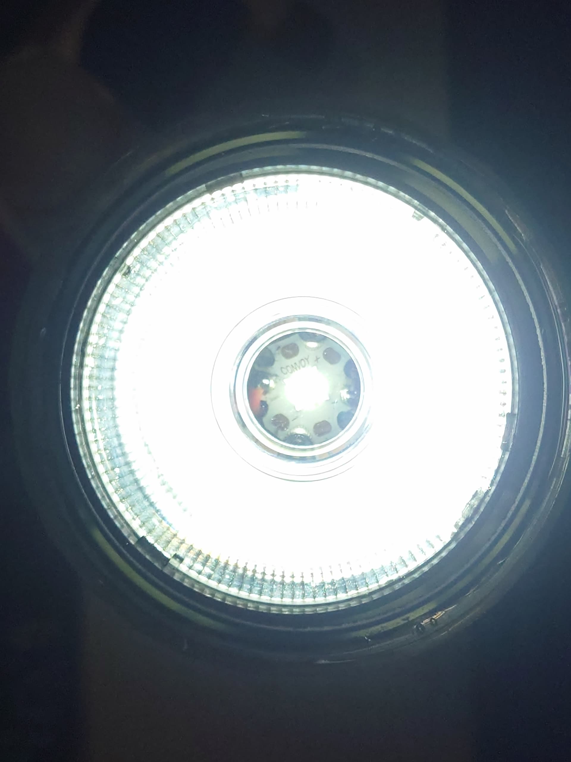
Once the epoxy had cured, I lined up and mounted the optic over the LED. This required some sunglasses with an extra layer of kapton tape while staring straight into the optic which in hindsight may not have been the brightest move.
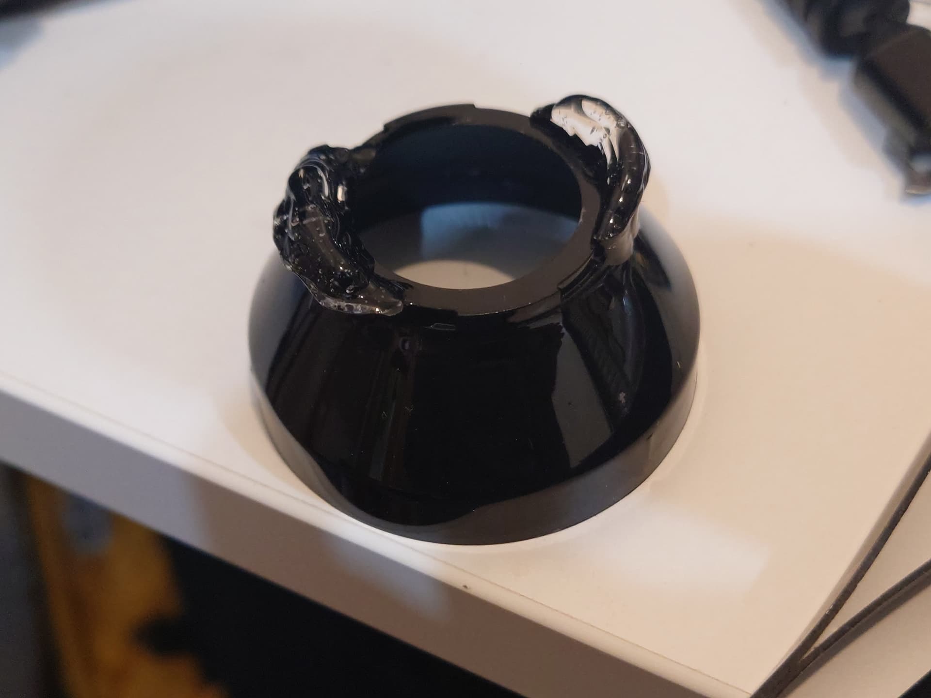
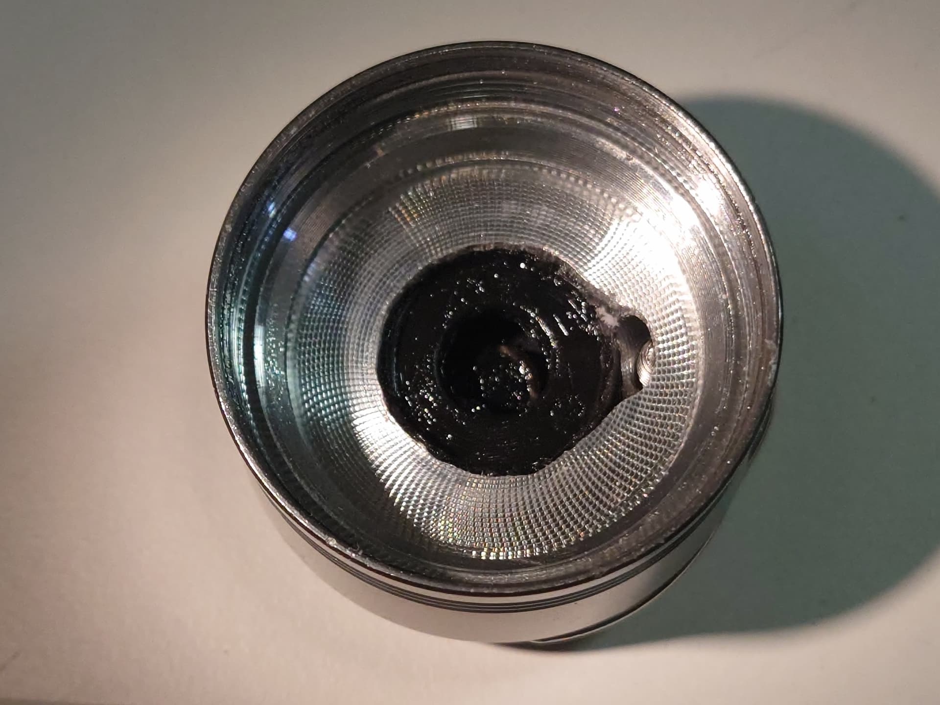
Then it was time to attach the lens. The 58mm lens was slightly smaller than the outer diameter of the head, and I planned on using more UV resin to mount the lens and give it a watertight seal.
First a thin bead of resin was applied around the gap between the lens and bezel, then blasted with UV from my handy S12 UV to cure almost instantly:
Then, a mould was consctucted out of scotch tape to prevent the resin from going all over the head while it was being poured:
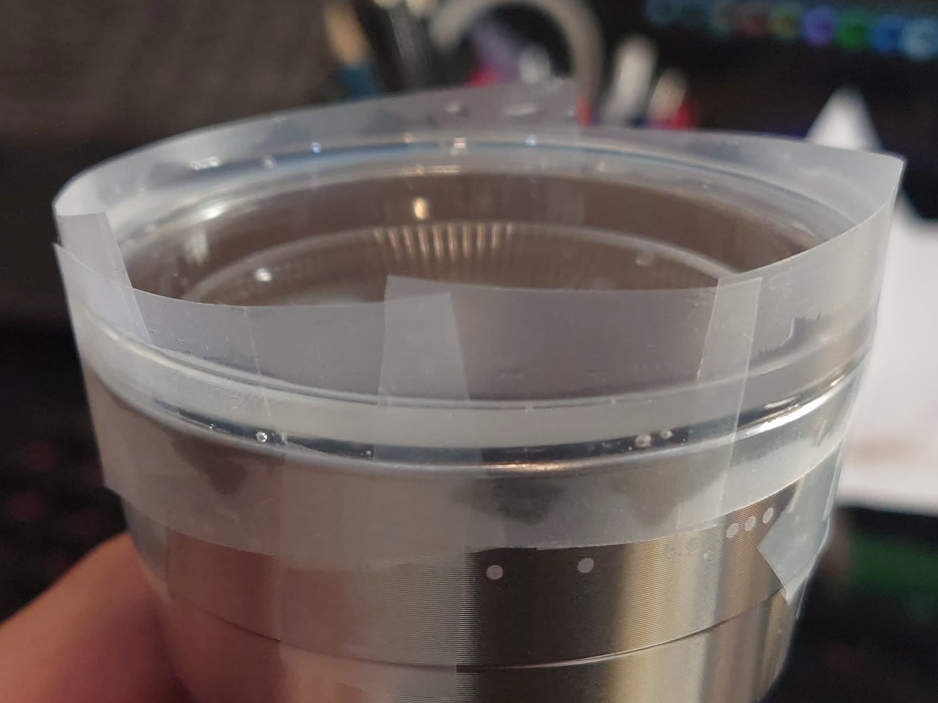
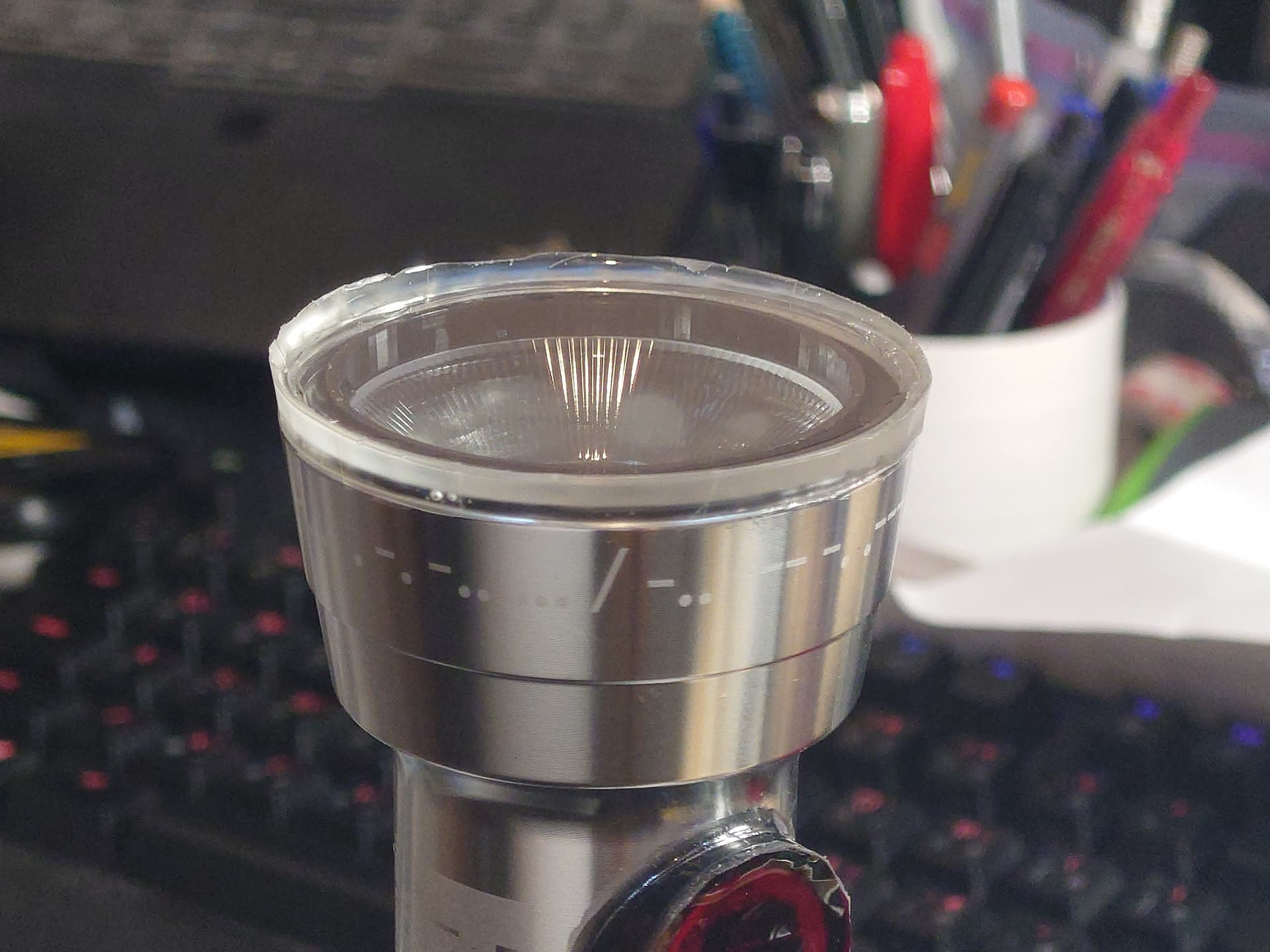
Once sufficiently irradiated, the tape was removed resulting in a nice flush looking bezel:
The battery:
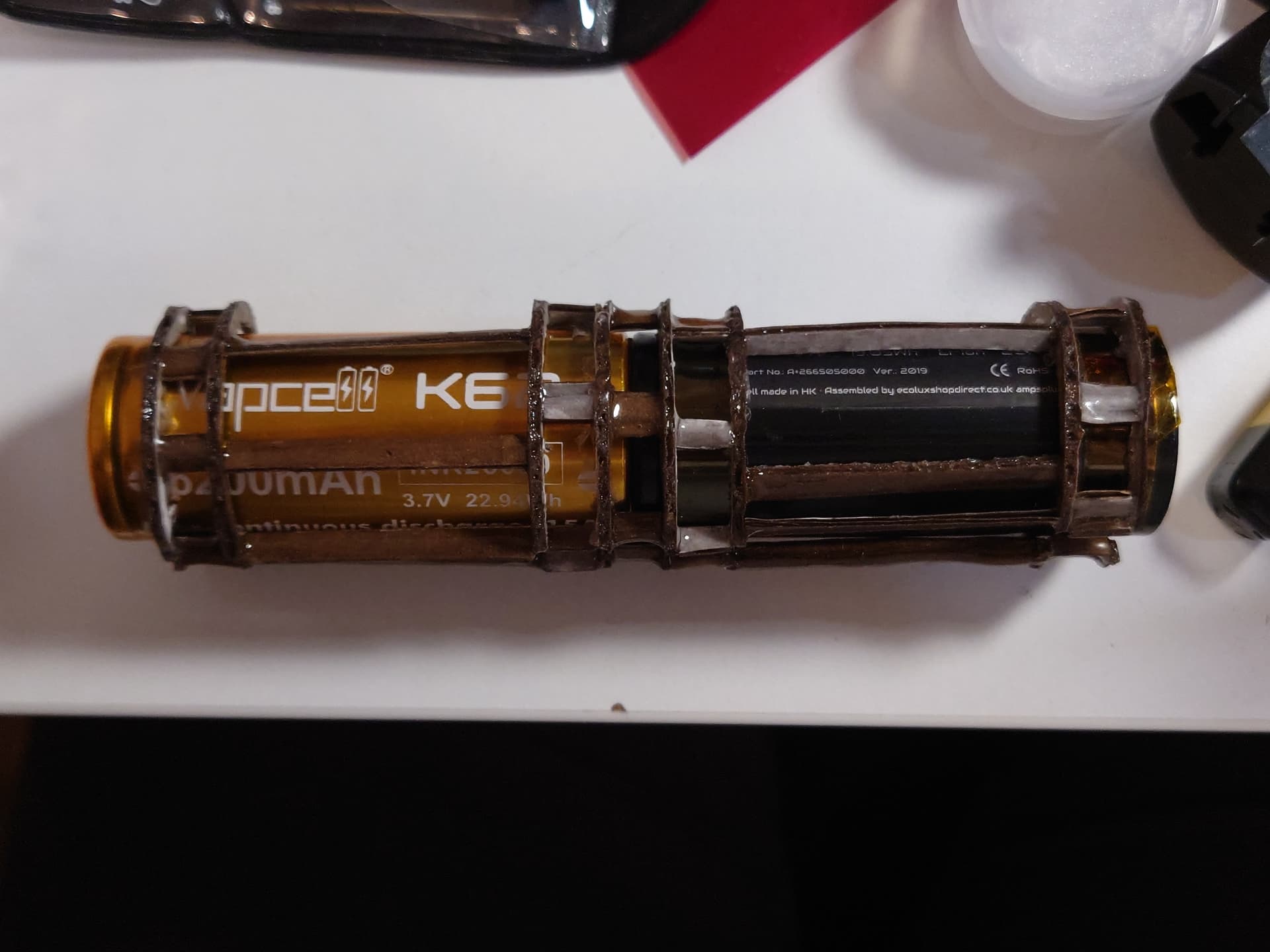
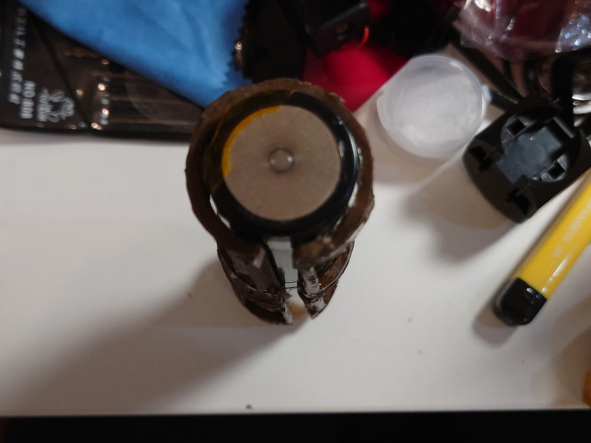
By switching from D cells to 26650s, I also needed a method to centre the cells and also allow clearance for the ground wire (more on that later). A frame was crudely made out of cardboard and more UV resin, but an improved 3D printed version is planned for the future.
A cursed looking battery caddy:
With clearance for a wire to run through:
(Note that the cells used in this currently are not the same capacity so I don’t run it for long and make sure to only fully charge the cell with lower capacity. K62s are still on their way)
Now for the tailcap:
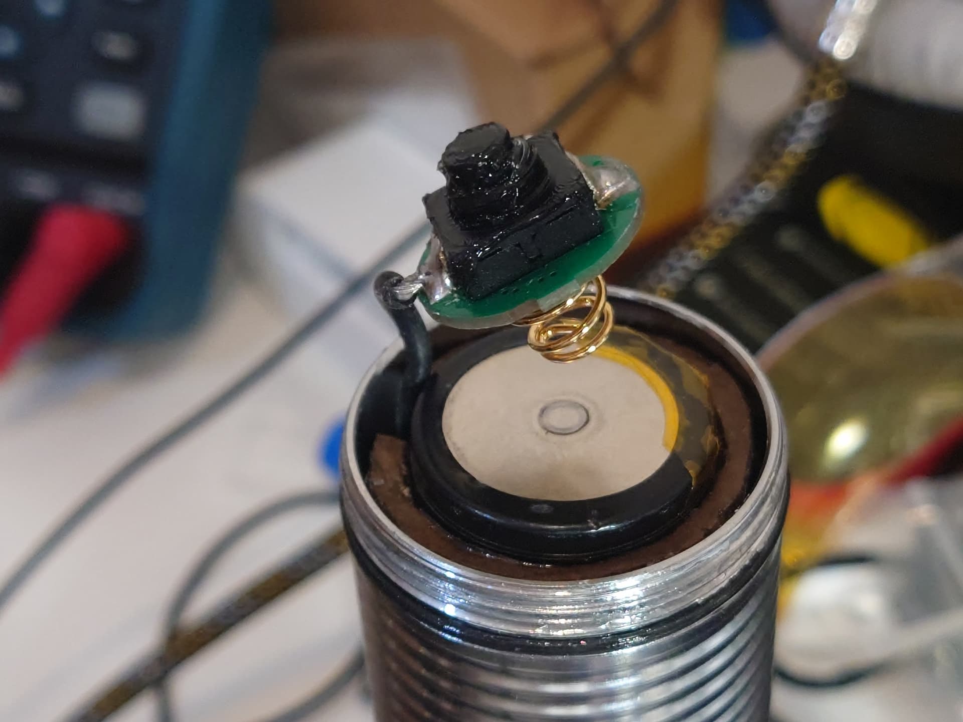
Originally the torch had a solid tailcap, but since the driver needs a tailswitch to control power a hole was made for one. To connect the driver to the switch, instead of connecting both to the tube I decided to use a bit of 18AWG silicone wire to connect them directly.
Due to how little space was available in the tailcap, a hole was cut out for the switch to pass through and rotate freely as the tailcap is screwed down. Generous amounts of grease was applied to allow it to rotate with less strain on the wire and give it a chance of being water resistant.
As the switch dome would stick out past the tailcap I drilled and tapped some holes around it to fit an M4 bolt through and allow it to tailstand again. It also helps reduce the chance of the switch being accidentally pressed or damaged.
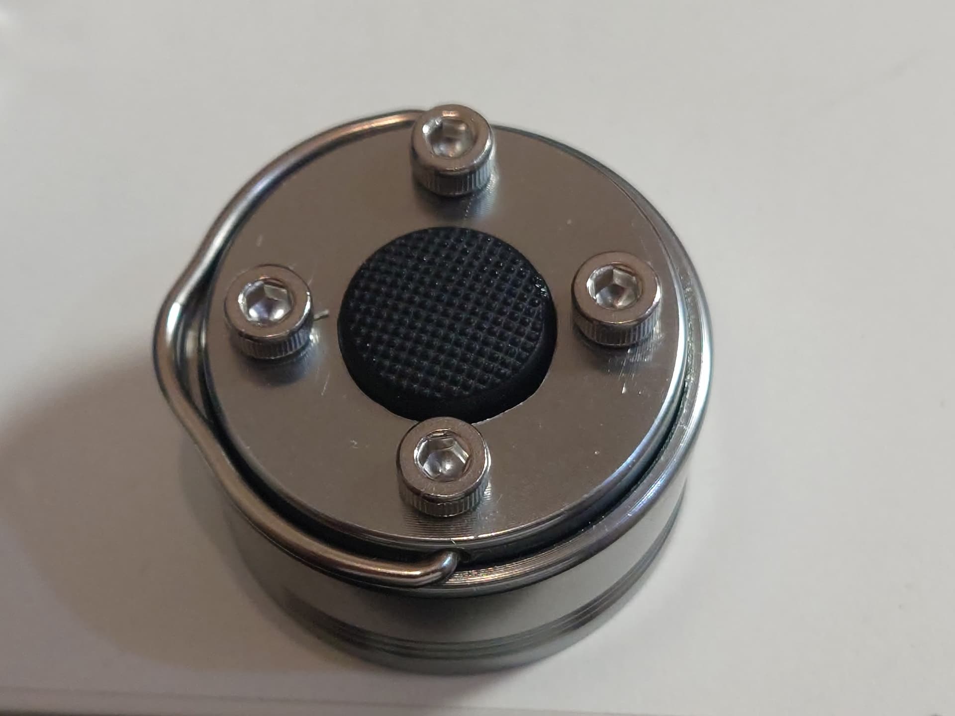
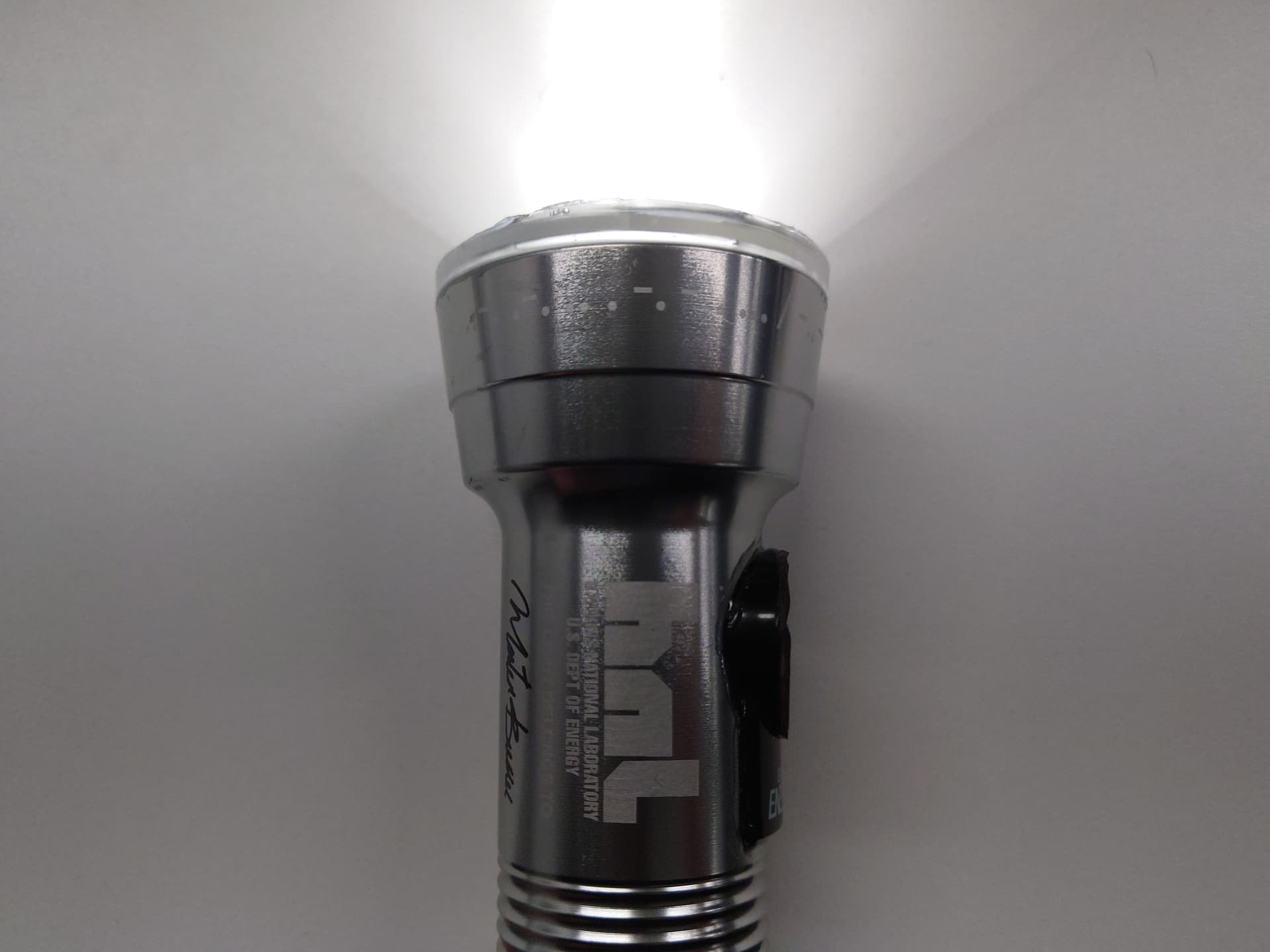
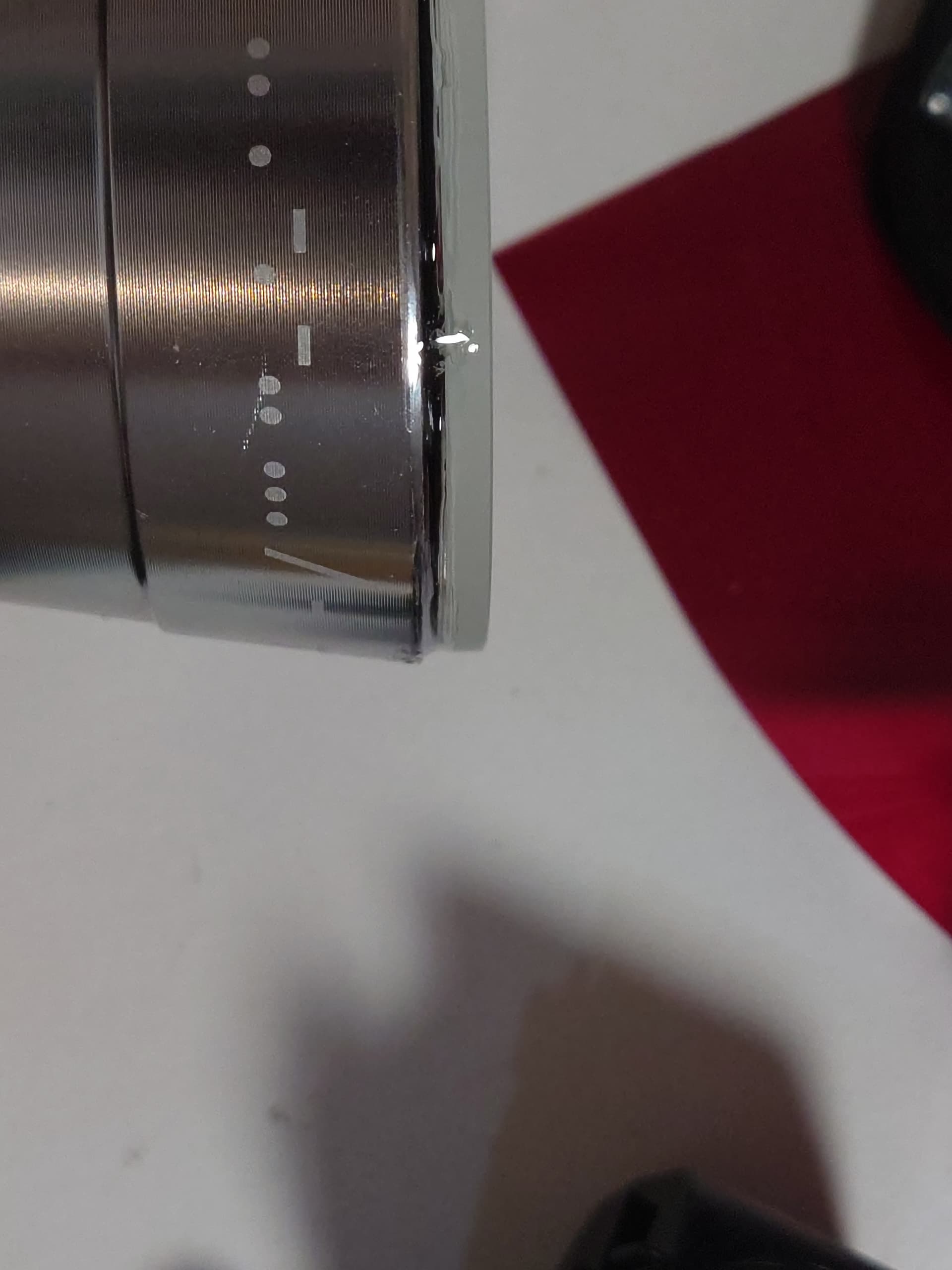
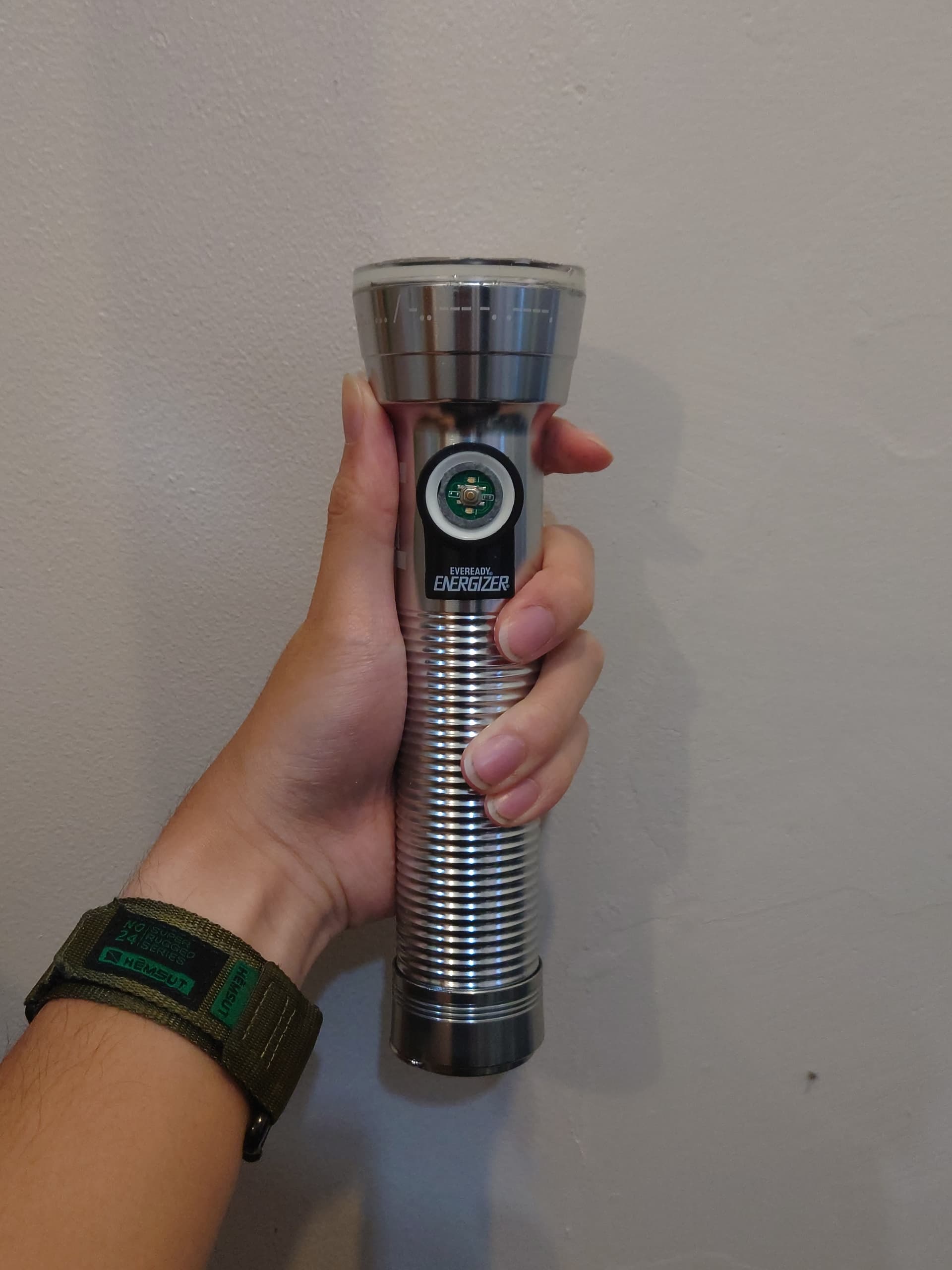
The completed light:
Some red gel was attached over the switch with VHB tape to give it some dust and water resistance, as well as making it look closer to the original. UV resin was also applied around the moulded plastic part to seal it.