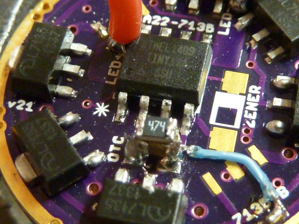
I can’t get a good shot that is in focus ![]()
One of these that I built has no LVP kicking in. I verified the resistors read ~22k and ~4.7K, reflowed them, reflashed the tiny13, and swapped the tiny13. Still no LVP kicking.
My other drivers built the same way and flashed with the same STAR OT program have LVP kicking in just fine.
:~
- What version did you build?
- Measure the voltage on that MCU pin.
- You must populate the 7135 next to R2.
Ah……The 7135 next to R2 was empty. Doh.
…just so I can build this driver. Hopefully, I’ll be flashing by then, but if not, can one of you zap the MCU for me?
I’m just getting back into modding after taking the last 5 years off—hey, my flashlights still work.
Got a fresh solder paste syringe in the fridge.
Got a 30X stereo microscope.
Got a toaster oven, controlled by a PID, that is awesome for reflowing.
Thank you everyone who has made this possible. I used to make my own PCBs from scratch, but lost the equipment when I got bought out.
It’s a lot better to be able to flash your own because you may need to tweak the offtime and LVP values. Please see this thread: Hoop - Guide: how to flash a NANJG / Qlite driver with custom firmware
RMM will probably flash whatever you need on an MCU for one or two USD, with shipping around $2 USD: http://www.mtnelectronics.com/index.php?route=product/product&product_id=311
Ya, like I know C. That Fortran I learned in college is gonna really help. …and my daughter learned Python at MIT. Some help. I’ve read enough to figure most of this out though, but the “fuse” settings are utterly alien to me. Before I sold the business, I used to have quite the shop. But I have something now that I didn’t have then—retirement :bigsmile:
Thanks. I’m getting to know Richard quite well, and buy from him rather than the Chinese at every possible opportunity, as I support local businesses.
Speaking of Chinese, I just ordered FT’s programmer, cables (female/female color ribbon, USB extender), and resistor value paks—though I prefer 1%. Probably be here in a month. I’ll go to Digikey and get the Pomona clip, along with a long list of components for this and other projects. Then the pain and frustration begins.
So thanks a lot, you guys, for turning me to the dark side. Building a flashlight I don’t need, just so I can build and program a driver for it. What have you done to me?
PS Can someone point me to where I can buy the latest version of this board please? Is this it?
https://oshpark.com/shared_projects/CUshrRzj
In case you weren’t being facetious about not knowing C & etc: it is not necessary to understand how to program in order to tweak those values and recompile. They are simply numbers which you may need to make larger or smaller. Comfychair wrote a straightforward guide for the procedure used to compile firmware; Hoop links to it in that flashing guide.
v022 is the current version.
Thank you. No, I don’t know C, just Basic and Fortran from 30+ years ago. I’m a hardware guy.
I have seen enough code in reading these threads, however, to feel confident in tweaking numbers here and there to get what I want. I can see building a robust “breadboard” flashlight so I can test my progress without having to assemble/disassemble a flashlight every time I want to make a change. I can also monitor battery voltage and amps easier that way. Too bad my scope went with the rest of the stuff.
Thanks again.
PS Is R1 a 22K or a 19.1K? I’ve seen it both ways.
Either value can be made to work, but in v022 of the board you’ll want to start with 22k in order to be closer to the correct values in the firmware.
In any case you may wish to calibrate your values. See ToyKeeper’s posts starting with #132 through #140 over here.
Thank you.
This is where the “breadboard” or bench flashlight, with an 18650 in a low-ohm holder and short wires (or a lab PS) comes into play. You monitor the voltage, and if LVP isn’t happening when you want it to, you either change resistor(s) or mess with the code and compile a new .hex file. Same goes for amps and modes.
Been reading up on AVRDude. Now DOS is something I can do! I plan on just learning to flash existing hex files, then move up to actually looking at code.
Is Amtel’s Studio 6.2 what people are using now?
The basic circuit for the Attiny 13A used to( and in stock form still does)have the voltage divider after the input diode D1 and in that configuration 19.1k for R1 and 4.7k for R2 are the correct values for stock firmware. With the Zener mod requiring the relocation of the voltage divider to see unclamped battery voltage as is the case for most of the custom boards designed here that allow for the Zener mod and preserve lvp, a change in the value of R1 was needed to account for the lack of voltage drop across D1. Many of us just borrow parts from stock mass produced boards including the ic so instead of just changing the code which many if us aren’t set up to do R1 is adjusted to 22k. If the Zener mod is opted for then a simple change of R1 (to ~48k-51K in the case of 2s) preserves lvp without any firmware changes. Everyone gets to play.
Six of these 22mm boards arrived today, and I have everything except for the OTC pull-down resistor. I have FT’s resistor value packs on the way. I thought I ordered V22, but the boards say V21 on them. They have the combo Zener/ROTC space though. It’s confusing because OSH’s site has V21 stenciled in the picture on the V22 webpage. I think I have the current board, yes?
Edit: I checked my OSH purchase history. I did buy V22 boards. They are simply stenciled V21 on the webpage, and what ships.
So now I have the hardware (USBasp/Pomona clip) and software (Atmel Studio 6.2), and they are working fine. It was really fairly painless.
What firmware is everyone using on this board?
Thanks again for making these available.
A bit off topic… This F13 will be my first modification. I got four of them, some parts from Mountain Electronics and some other stuff. They will be going to work on our liveaboard boat. Anyway, hello to all and a big thank you to BLF and those who drive it forward!
Doug
i want to drive a XHP70 with this driver with Zener mod
and are the below components correct for a standard
programmed star off-time with memory from mtnelectronics
with 2x 18650 cells in series.
R1 - 22k 1% resistor (0805)
R2 - 4.7k 1% resistor (0805)
C1 - 10uF capacitor
OTC - 1uF capacitor
R3 - 220R 1% resistor (0805)
Zener - 4.3v SOD-123 zener
can this driver be built to order?
I use 20awg with the F13 trying to figure out what to do about driving the xml2 4c on a copper MCPCB I installed.
R1 needs to be higher for the double voltage. I use 47.5K for double voltage drivers.
Is anyone selling these drivers made up, or another F13-sized driver?
Or have pictures of how to get a smaller driver mounted in the light?
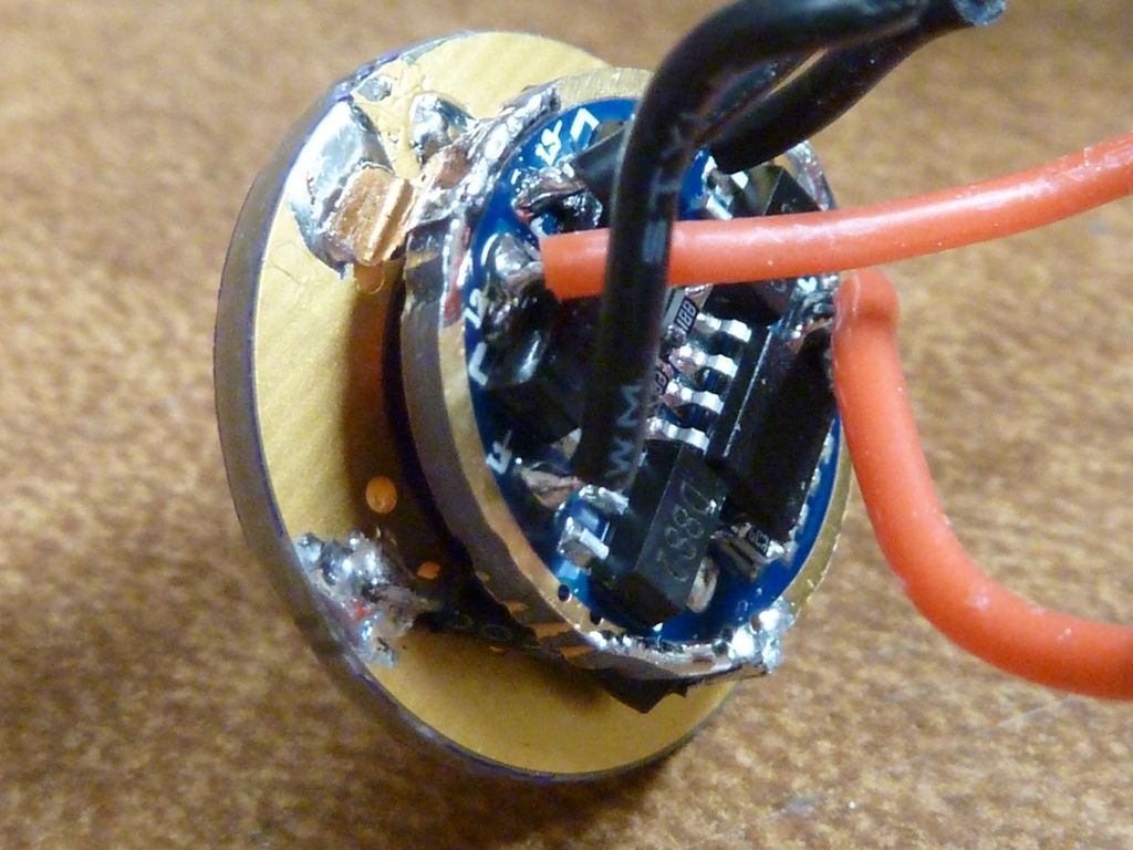
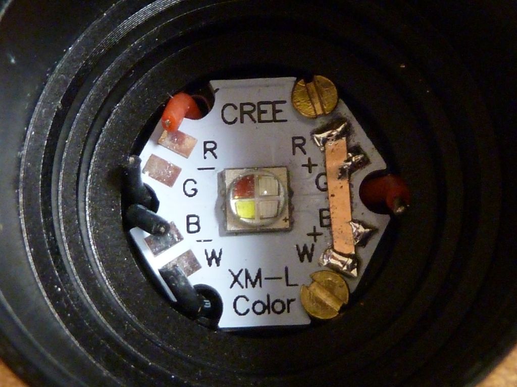
I've done F13's both ways - piggyback or replacement. Been look'n, but can't find what you may find more applicable, but these are from F13's. Here's one I did with a quad color driver:
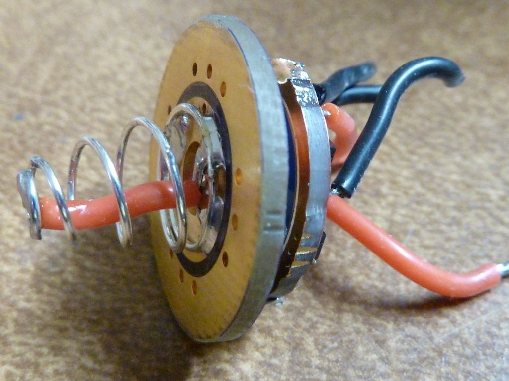
Another setup for an F13:
Can this be used with a LDO or just a zener?