Exactly. Wound wire from toy motor would work great as signal wire, need no insulation, and set you lifetime supply from one motor salvage.
Just dont steal it from your crying kids, thats not cool. ![]()
Exactly. Wound wire from toy motor would work great as signal wire, need no insulation, and set you lifetime supply from one motor salvage.
Just dont steal it from your crying kids, thats not cool. ![]()
Today I received mine. Love it for money!
Just wondering, what’s going on with one of my lights driver:

Full size image here.
That is the FET driving the light, those pins that are blob soldered are all internally connected…other than being a HORRIBLE solder job it shouldn’t cause issues
I wonder if an ATtiny can be grafted into this driver and be used to drive the FET for multiple modes aka STAR driven?
Question, that black block connected to the blue leads, that is the external charge port correct? If it is, it looks like you could cut the wires, and solder in one of those TP4056 charger control modules
Looks like it might be quite “modifiable” is there much room between the driver and the back cover?
I should have mine in soon
… Sure if your very crafty in your rework to include the propper components to support it.
…Yes it connects directly to Pos and Neg of cells
…not much but fair amount beside the driver.
You may be able to squeeze a TP4056 charger control depending on variant; especially if you shift the existing driver to one side. Or maybe externally shrink wrap the TP4056 board as part of your charge cable instead.
I was able to fit both a 17mm nanjg 105c and a 12x25mm nikon battery charge board. Though my plans are to just hot-wire the 105c to controller to the existing FET and forgo a charge controller since the batteries are easily accessible.
Maybe these pics will help. The 105c and Charge Board peaking through.

inside view… tight fit

The FET is fine enough to drive the light…the PWM (pin 6) out of that 105C can drive it, this is why I wanted to put a BLF custom driver minus the FET to use the PWM output
Designing a full board would probably cost quite a bit (maybe even more than the entire light)
I will try to work on one, but not sure if people would be interested…more hassle than it’s worth…doing the “addon” is more cost effective
Very cool mod you did there though…great job!
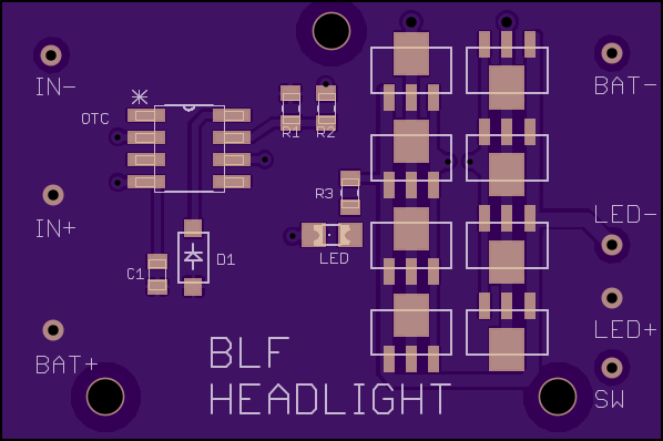
As promised…preliminary release of a Nanjg 105C equivalent compatible $7 headlight driver
2 layer board of 1.5x1 inches (38x25mm). $7.40 for three
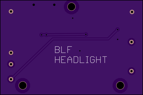
Top
Bottom
R3 is a 100 ohm 0805
Everything else is stock Nanjg 105C, with Star Momentary Werners UI, you can have 5 levels (heck you could have 10 if you wanted) round robin with this
SW is tied into pin 2 for momentary driver support
I haven’t released it because the copper pour went all stupid under the 7135’s…don’t know how to fix it but it should work, the led on the back will light up when the light on the front comes on…it will be PWM driven as well. - edit - went back and fixed alot of the goof on the copper pour, added a few extra vias, doubled the power trace width, and it cleaned it up - edit -
I measured the board
37.87mm wide, 25.17 tall
2mm holes
2 bottom holes are 5.5mm from the sides and 2mm from the bottom edge
top is centered and 1.25mm from the top edge
If anyone is interested I would like one of the Eagle guru’s to review my work, before I share
Great! Highly appreciated.
I'd like to order 2x3pcs, as soon as it's reviewed and verified.
Thanks for your contribution!
Just a mad thought, would it be feasible to replace the rear light with a small DVM like this?
With a small momentary switch, you could quickly check cells in place in the field, great if you're using unprotected cells. I don't care for the rear light anyway.
Don’t see why not…need a push button to break the link to the DVM, then wire in the leads to the S- and S+ pads
Oh yeah, did the no strobe mod as well…no more steenkin’ strobe to turn off the flashlight H>L>OFF
Maybe connect the DVM through a n.o. reed switch, put a magnet in the head. When you want to check, bring the head near the battery pack to get a reading. Wouldn't have to find a place to mount a button.
I got mine and am satisfied with it.
I wanted to buy another but the coupon does'nt work. Has it ended?
$7 coupon ended, but it's in the 'Buy one, get one' sale. 2 for $11.38 plus postage, ~$9ea. for me. Still reasonable.
Thank's for the update! Tempting, but because my single light was marked "value USD 15" I don't dare buying two (I'm allowed to import for $14).
I'll try some cheap LED spots instead...
They marked $20 for two but I’m sure that you can request them to mark any value you want to.
Use code midyearbest
Brings torch down to $3.10 and shipping is $3.50.
Shipping was 3.40 so total of 6.50 for me. Thanks ![]()
Thanks a lot, ordered
I happen to read this thread again after posting many days ago. You guys are a bad influence. ![]() At about $9 each shipped, a pair is coming up.
At about $9 each shipped, a pair is coming up.
Oh well…
Don’t use the get-one-free code. Read my post about 4 up.