Two typical color shifts are known for de-domed LEDs:
- color becomes always warmer (see DrJones explanation, https://budgetlightforum.com/t/-/13495 )
- some LEDs also show an unpleasant green shift
But what system is behind these color changes?
I was so curious that I have inspected a handful of LEDs (six Crees and one Nichia) with a colorimeter (Spyder4 sensor + HCFR software).
| No | LED | color bin | flux bin (just for completeness) |
| 1 | XP-G2 | 7C4 | R3 |
| 2 | XM-L2 | 7B4 | T3 |
| 3 | XP-G2 | 5A2 | R4 |
| 4 | XM-L2 | (3A...3D) 0E3 | T6 |
| 5 | XM-L2 | (0A...3S) 051 | T6 |
| 6 | XP-G2 | 1D | R5 |
| 7 | N219B-R85 | SW45 | D220 |
The Crees already have been sorted from warm to cool.
I used the nominal current from the data sheets (XP-G2: 350mA, XM-L2: 700mA, N219B: 700mA).
1. color temperature, color "fault"
Here are the results, as grey circles. An arrow shows a change resulting from de-doming.
The labels A, B, C and D65 are basic marks from the software and have no particular meaning here.
The software also prints some basic color temperature values for orientation.
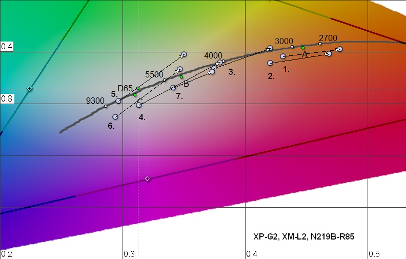
"direction of color shift"
You can imagine a pattern, a swarm of curved lines, which suggests a "direction" of the respective color shift at each point in the diagram.
XP-G2 and XM-L2 seem identical (compare 5 vs 6, and 1 vs 2, I guess it's just the same phosphor.
The Nichia (7.) deviates slightly from the Cree behaviour, but still matches the common pattern.
"length of color shift"
The resulting color also strongly depends on the "length" of the arrow, though.
However, be careful with interpreting the length of the shift, because lines of constant color temperature are askew to
the long, arcuated black body line. And they are more dense towards higher color temperatures at the left.
(For an illustration search for "ANSI C78.377", or see the picture http://en.wikipedia.org/wiki/Chromaticity#mediaviewer/File:PlanckianLocus.png in the wikipedia:chromaticity, http://en.wikipedia.org/wiki/Chromaticity .
The shift for no. 4 seems to be the greatest, but in fact it's just an ordinary shift (see table below).
conclusions?:
Usually de-doming is most interesting for LEDs with the highest flux bins. Inevitably, that's the cool white variants, those with the "thinnest" phosphor. And just these are the most critical. Here you can imagine, which color bins are the most promising for avoiding a unfavourable green shift. The lower the color bin is in the diagram, the better.
For Cree LEDs you can look them up in the PDF XM-Family Binning & Labeling, http://cree.com/~/media/Files/Cree/LED%20Components%20and%20Modules/XLamp/Data%20and%20Binning/XLampXMBL.pdf , especially "ANSI Cool White" on page 7.
You will notice a problem when looking at these vendor data sheets: the area for a color bin usually is quite large. For the same label, a color bin from the "lower end" will be much more promising than one from the "upper end". You won't know at the time of purchase. If you want to be sure and have no better info you might have to buy more LEDs and select the favorable ones. But you will have a good idea which color bins are promising at all.
Here is a table with the numerical values. I haven't bothered to calculate errors, just imagine the grey circles vary at most 1/3rd of their diameter.
| No. | LED | color bin | color temp. with dome [°K] | ...without dome | ..difference | CIE x, y with dome | ...without dome |
| 1 | XP-G2 | 7C4 | 2983 | 2436 | 547 | 0.431, 0.392 | 0.478, 0.406 |
| 2 | XM-L2 | 7B4 | 3061 | 2469 | 592 | 0.421, 0.379 | 0.469, 0.397 |
| 3 | XP-G2 | 5A2 | 4096 | 3328 | 768 | 0.375, 0.369 | 0.421, 0.408 |
| 4 | XM-L2 | (3A...3D) 0E3 | 6745 | 4037 | 2708 | 0.314, 0.298 | 0.380, 0.380 |
| 5 | XM-L2 | (0A...3S) 051 | 7869 | 4959 | 2910 | 0.297, 0.305 | 0.350, 0.396 |
| 6 | XP-G2 | 1D | 9158 | 4985 | 4173 | 0.294, 0.275 | 0.347, 0.367 |
| 7 | N219B-R85 | SW45 | 4470 | 3678 | 792 | 0.360, 0.353 | 0.391, 0.373 |
The results for the cool white LEDs appear too cold for me. Also I believe that the LEDs actually are more "greenish" (upwards in the diagram), the colorimeter shows them slightly towards purple (downwards). If so, it's a systematical error, there's no variance: repeated measurements result in almost congruent circles. The values for moderate color temperatures seem to be quite reasonable.
I have a XM-L2, color bin 1C, flux U2 in reserve. It's located exactly between 5. and 6. and I haven't dedomed it yet, in case I find out that I still want to measure something with dome.
2. color reproduction
In contrast to color temperature, you can't tell about color reproduction (CRI) from the above results.
Instead, I made a comparison with a color checker (datacolor).
Conveniently, there are two LEDs which are located very closely:
left picture is no. 3 with dome, center picture is no. 4 without dome. right picture is a mouse-over of both.
(I don't know if that works in all browsers, so I also added the plain images)

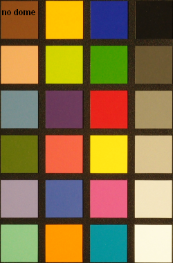
I can't notice any real difference. At least for LED no. 4 the color reproduction doesn't seem to suffer.
3. reason for increased luminance?
At first, the following, you might have seen occasionally, seems to be a quite plausible explanation :
De-doming results in a smaller apparent die size (roughly half of the original size).
But as still almost the same amount of light is emitted, "light per area" should be increased now?
But in fact this is not the actual reason! and it conflicts with "conservation of etendue". If that were the explanation, luminance would have to rise also if you removed the magnifying effect of the dome by making it flat (either by squeezing it or by slicing off the upper part). The apparent die size also becomes smaller then, but as a matter of fact the luminance does not increase then. Luminance only increases if the dome is removed.
The following gif animation illustrates this.
It's four pictures of the very same LED, through a sun filter, each with the same current, f-stop, shutter speed and focal length
- with dome
- dome squeezed flat with a thin glass plate (smaller die, but still same luminance)
- upper half of dome cut off with a scalpel (smaller die, but still same luminance)
- de-domed (smaller die, higher luminance)
The pictures were shot with slightly different distances, that's why size varies abit, but luminance is not affected by distance.
Well, with sliced dome ("dome cut even") the luminance seems to be slightly increased. Here, dome thickness is smaller, and I guess that DrJones explanation then applies to a small amount.
[gee, my first article with images, tables and links, what a mess to get all these right, hope I haven't confused other things about this..]
edit 2014-08-04: typo found
