I was very silent recently, my new job has been taking a pretty big toll on me, forcing me to dial most of my hobbies down to zero until I got adjusted.
I feel like I’m slowly starting to get used to the hours and tasks, so I’m getting back into my hobbies a little.
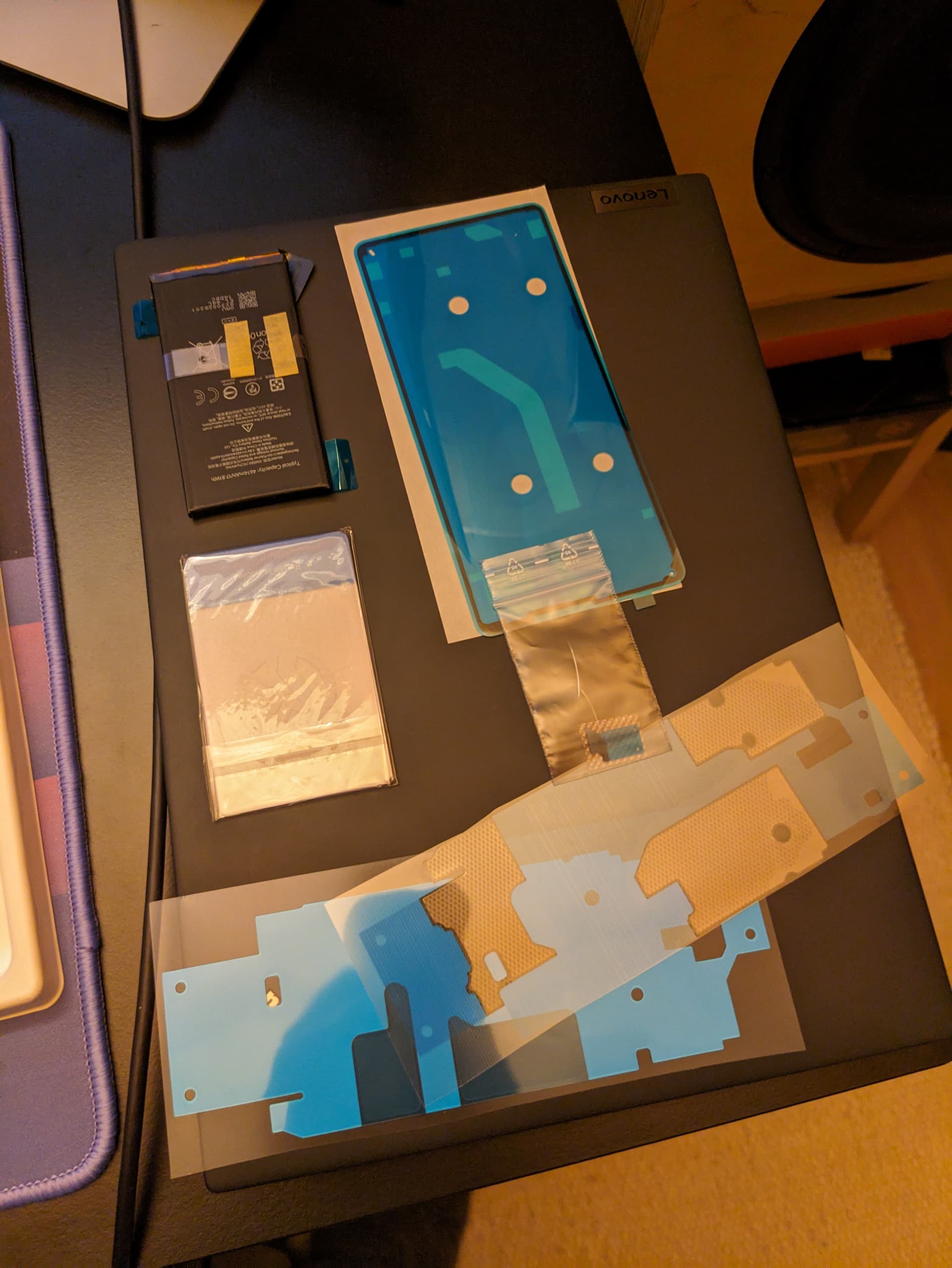
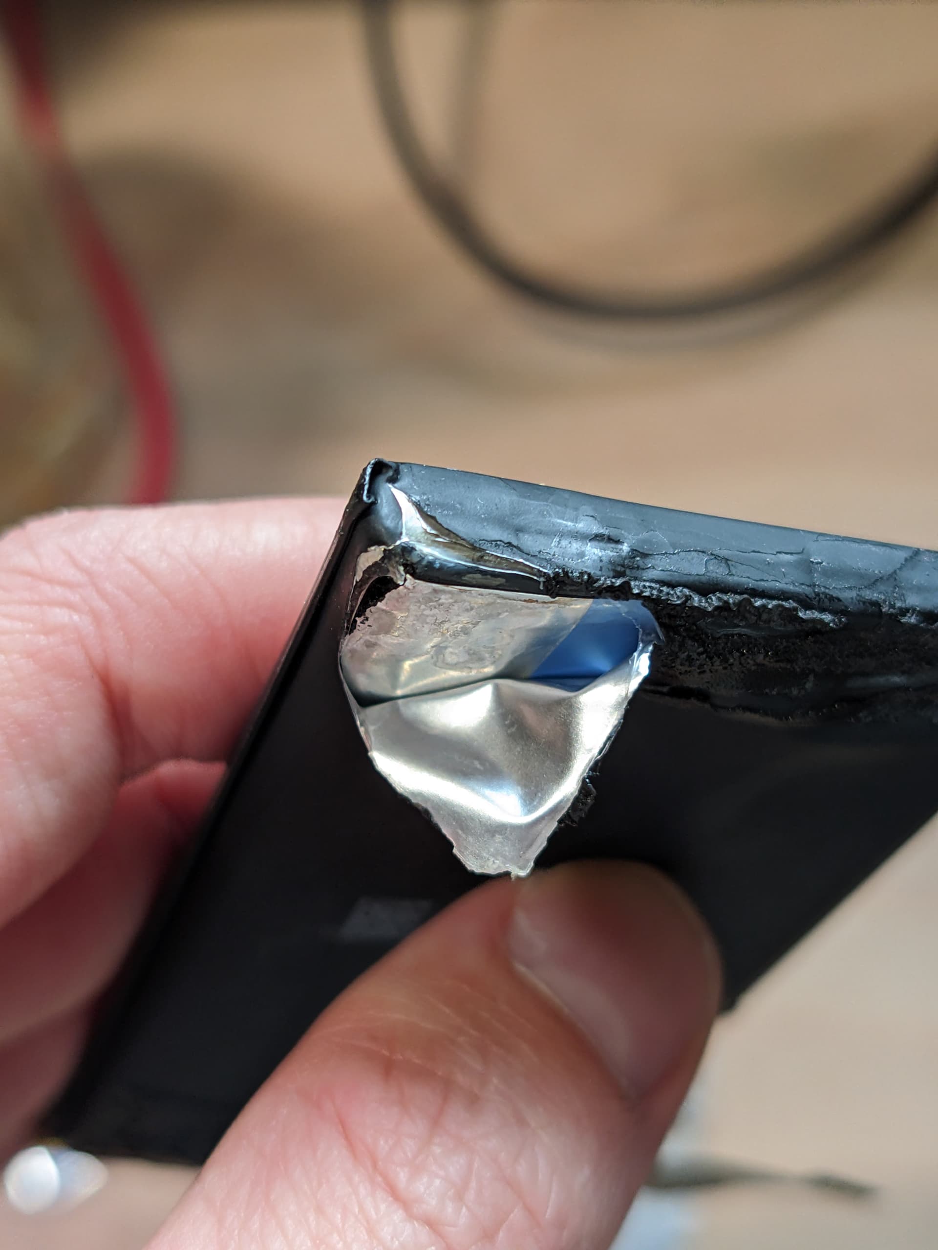
This will be a bit of an update post on what I’ve been up to in the past month or two. First of all, my spare battery showed up. Google glued the old one in so tightly I ruptured the cell despite being super careful and using tons of isoprop to weaken the glue. I was incredibly lucky it did not combust…
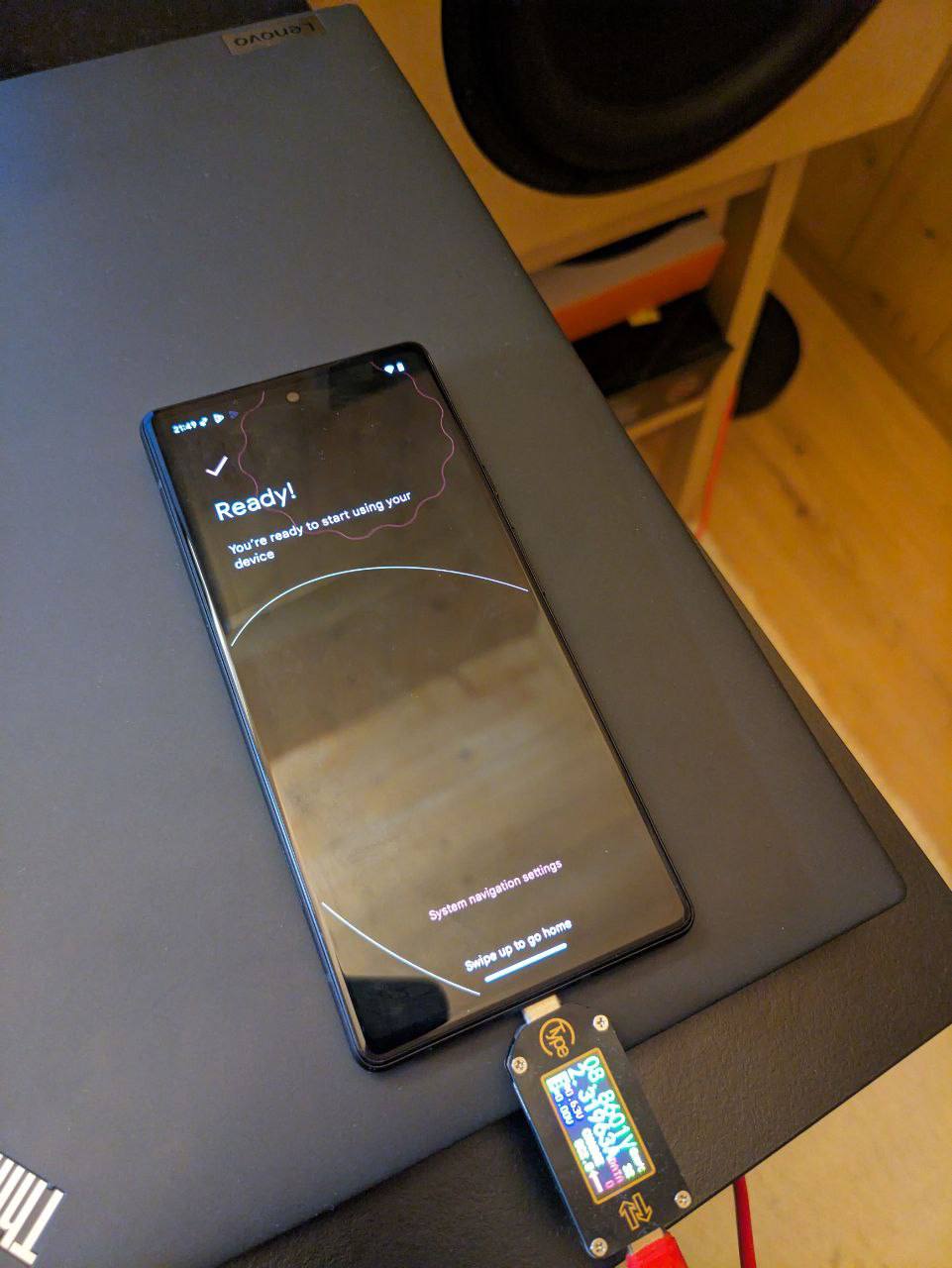
Got the phone working now, and it’s been awesome to use. Very happy I decided to fix it. I even got the new Android 15 today which came as a surprise, as I thought the P6 was scheduled to only get security updates after A14.
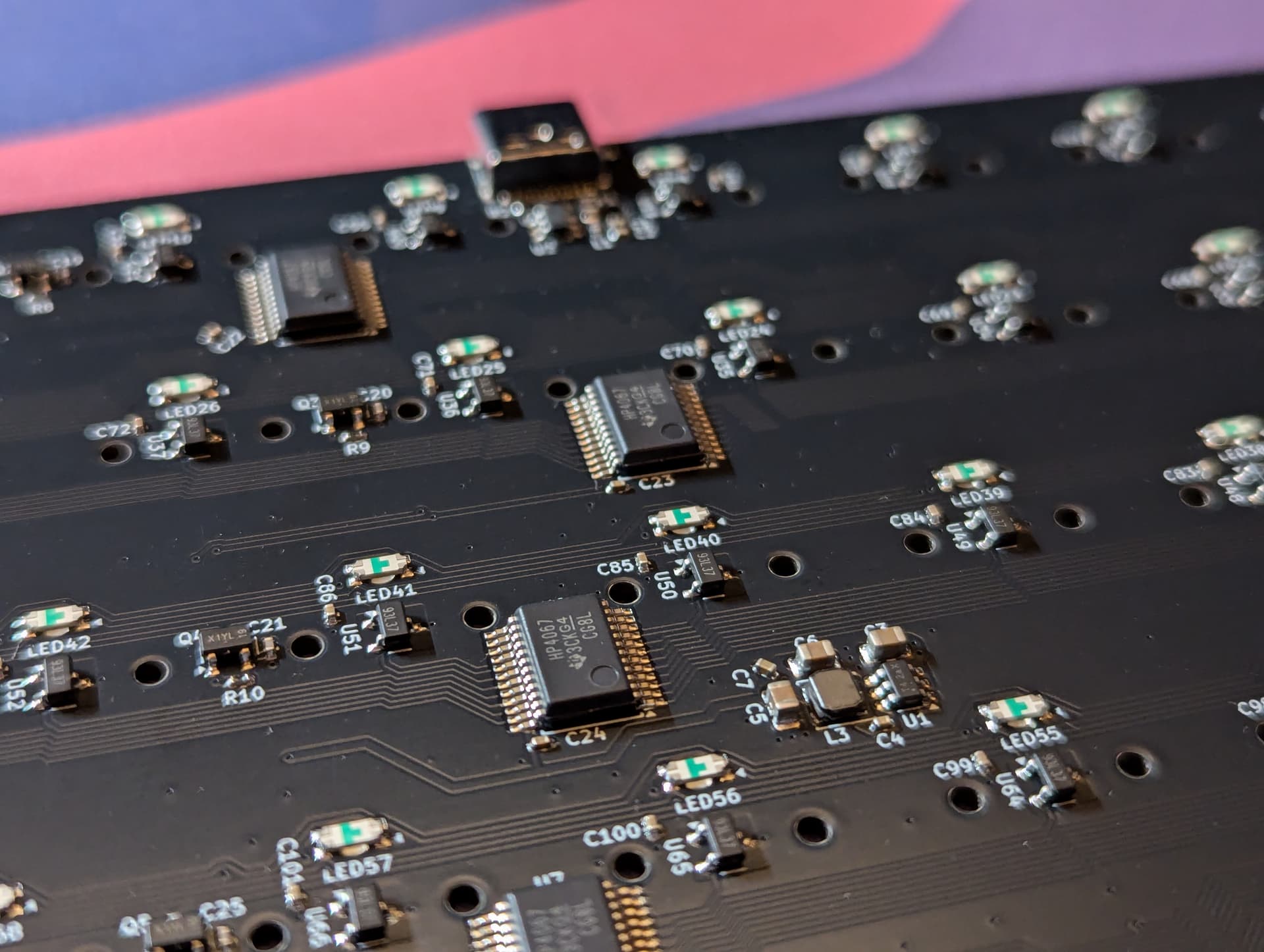
I then received some very cool prototype for a hall effect sensor based computer keyboard PCB on which I had been working for a while ( You can check out Wooting HE60 for some info on how the tech work and what it’s good for if you’re interested - it’s a commercial product with very similar specifications). Can’t show too much yet as the PCBs are under NDA, but I think a little teaser won’t hurt.
85 hall effect sensors and 95 RGB LEDs, I think. Very challenging to squeeze on 2 layers with good separation between analog and digital paths etc.
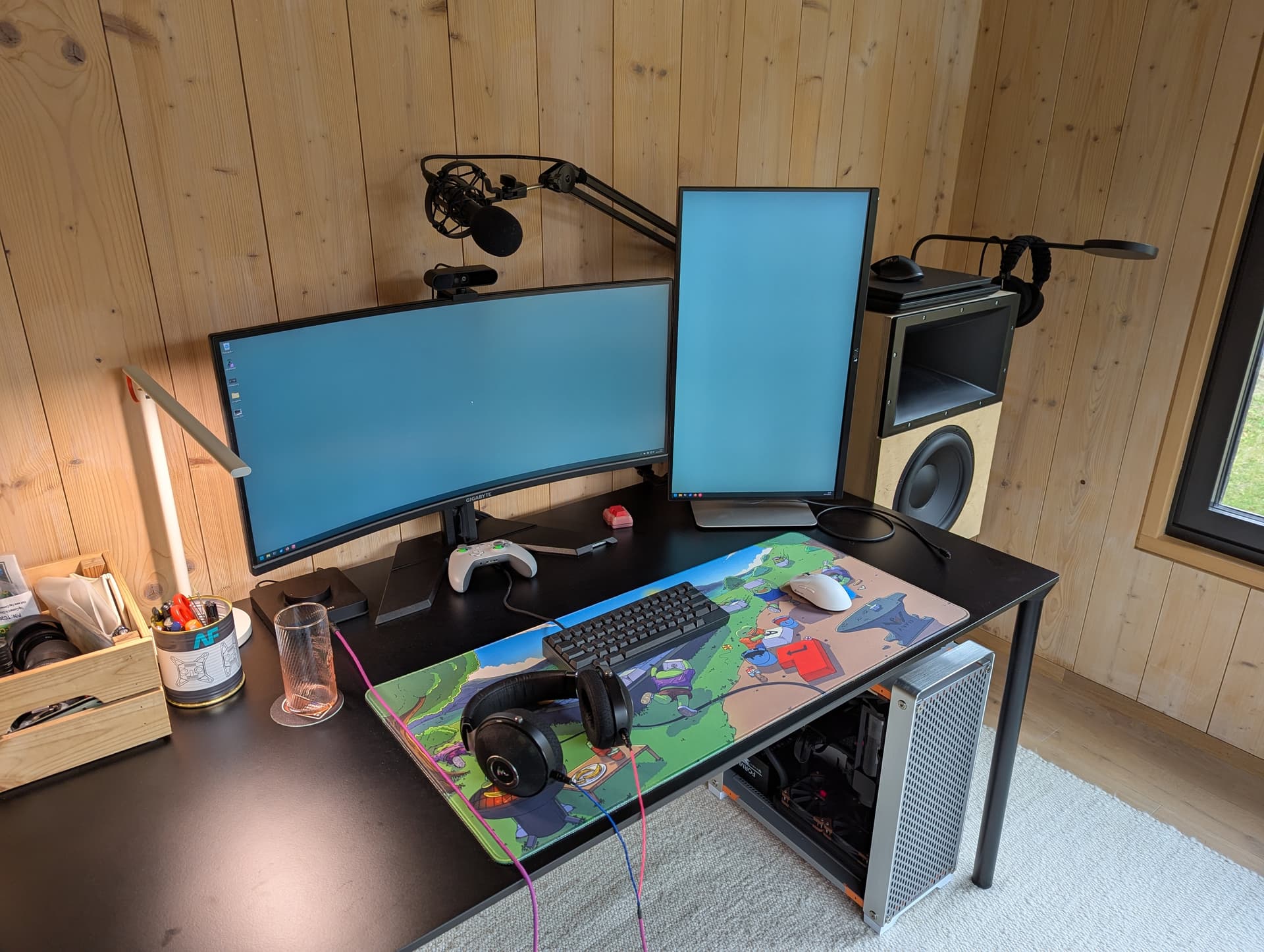
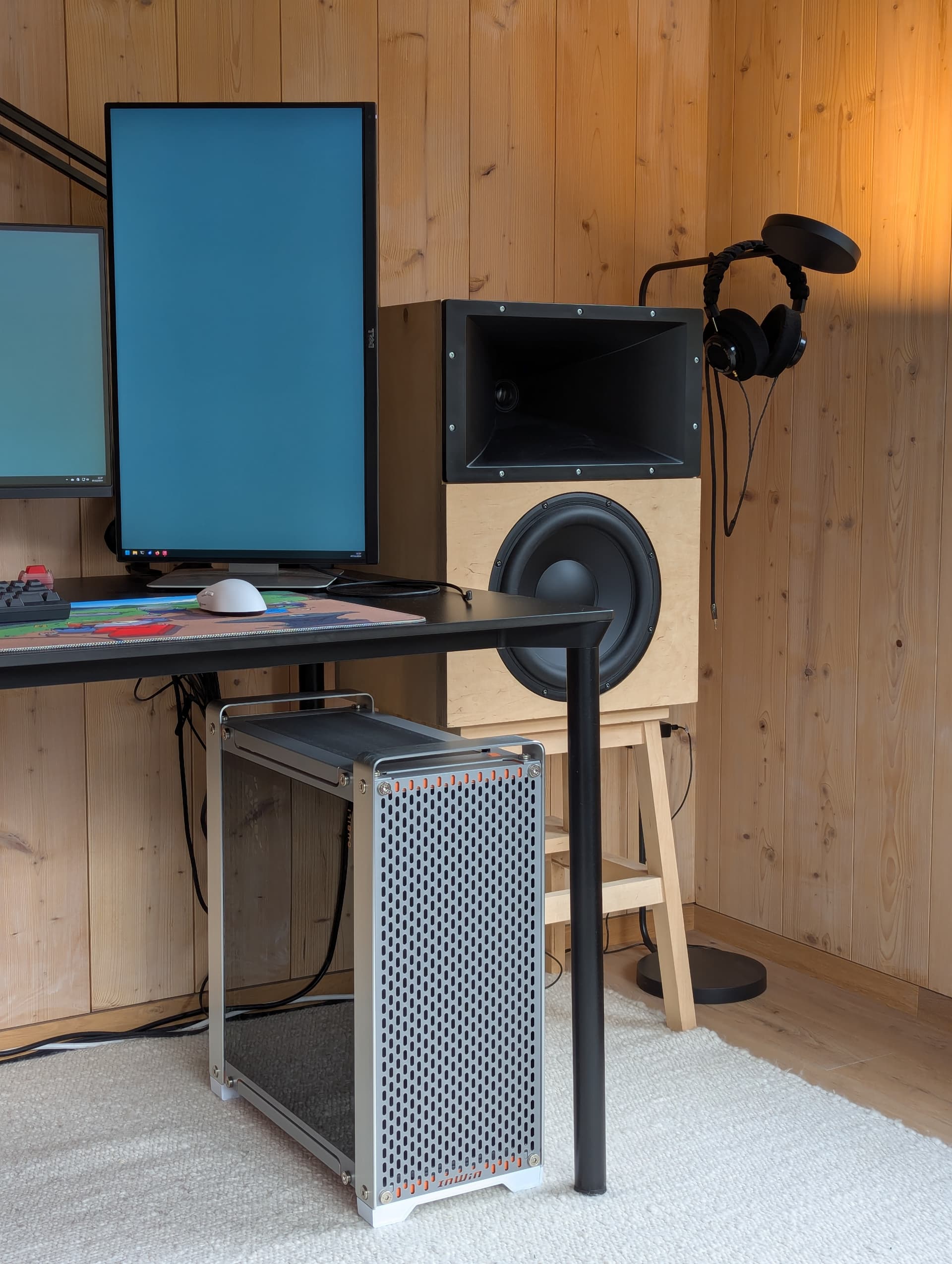
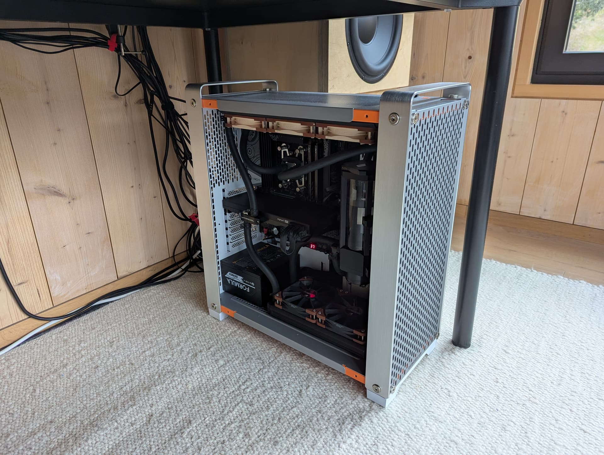
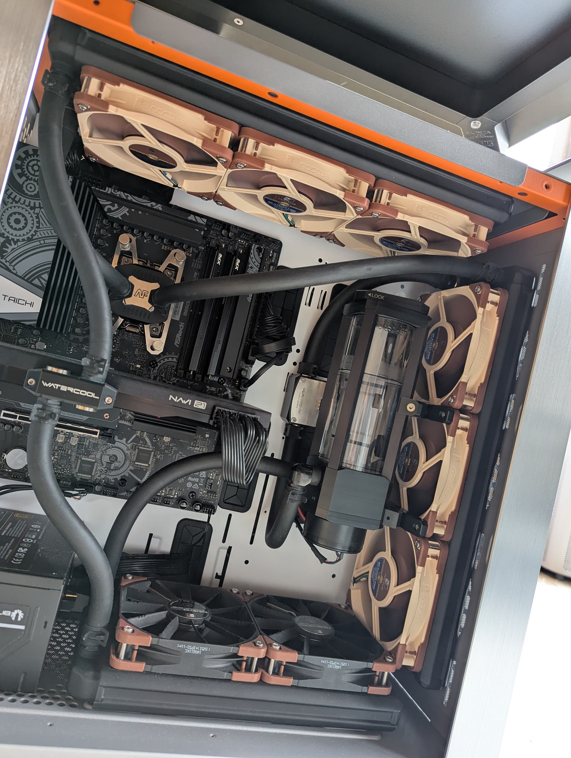
Lastly I finally built myself a desktop PC again after almost 2 years of being notebook only, so I can catch up on playing some games I had wanted to play for a while now. Sadly I’m short on time, so didn’t play too much yet ^^
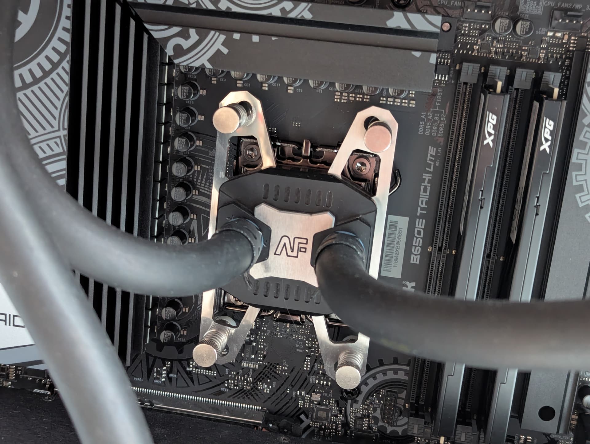
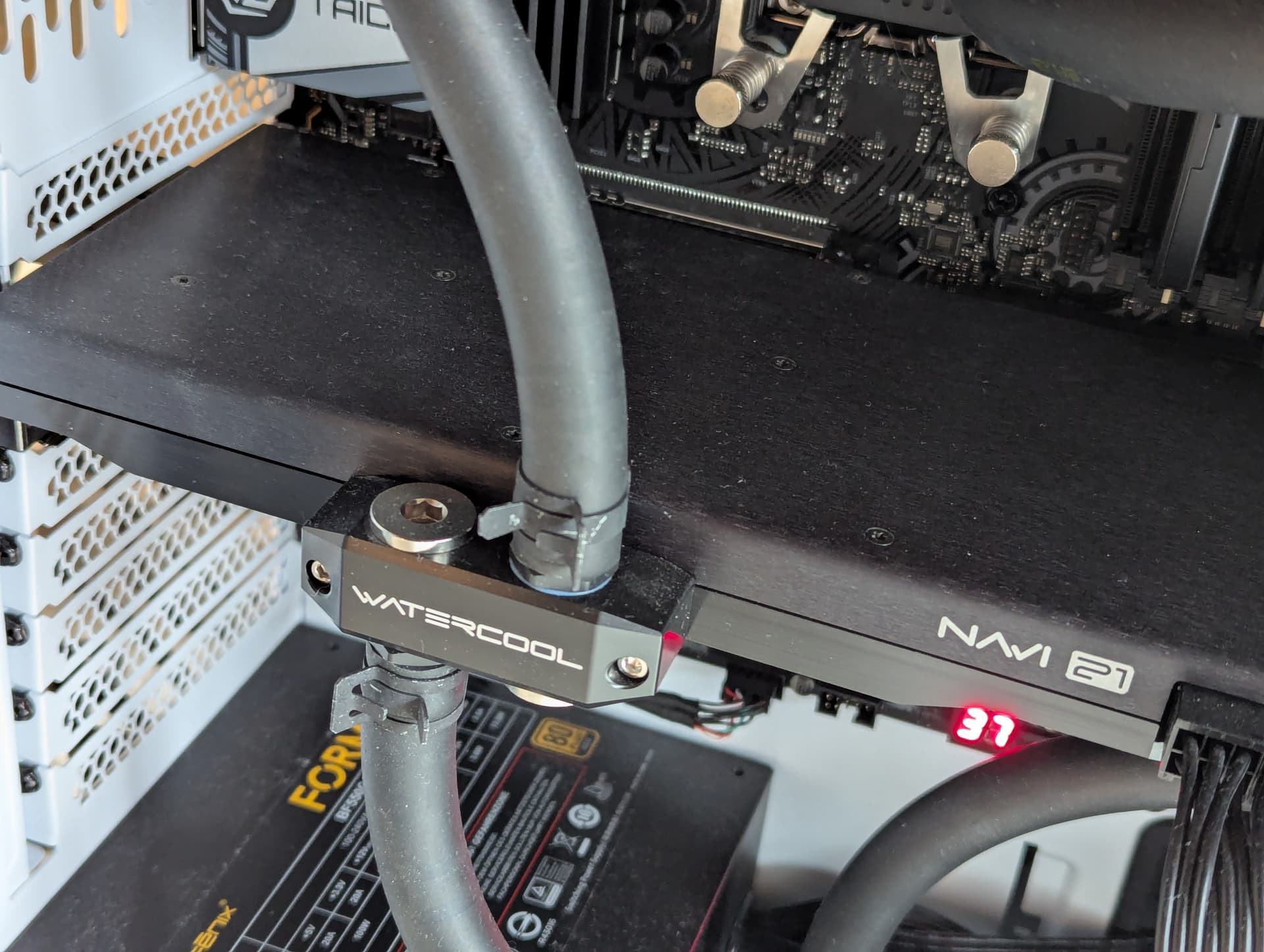
I went for a Ryzen 7 9700X on an ASRock B650E Taichi Lite with 64 GB of DDR5-6000. It was surprisingly hard to find components without RGB crap. The GPU (RX6800) as well as SSDs and most of the water cooling were carried over from my previous PC which had a broken motherboard.
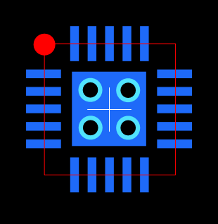
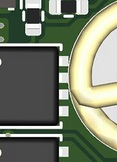
Oh, yeah, when the package has a thermal pad I’m doing the same. The 28pin “VQFN” ST used for this chip is very weird in general. No thermal pad, and 2 strange 45° chopped pads in the 4 corners.
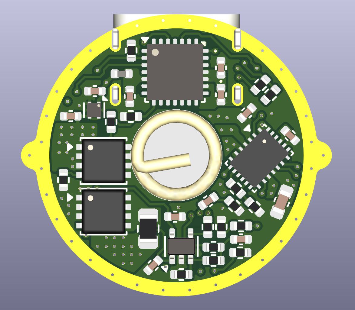
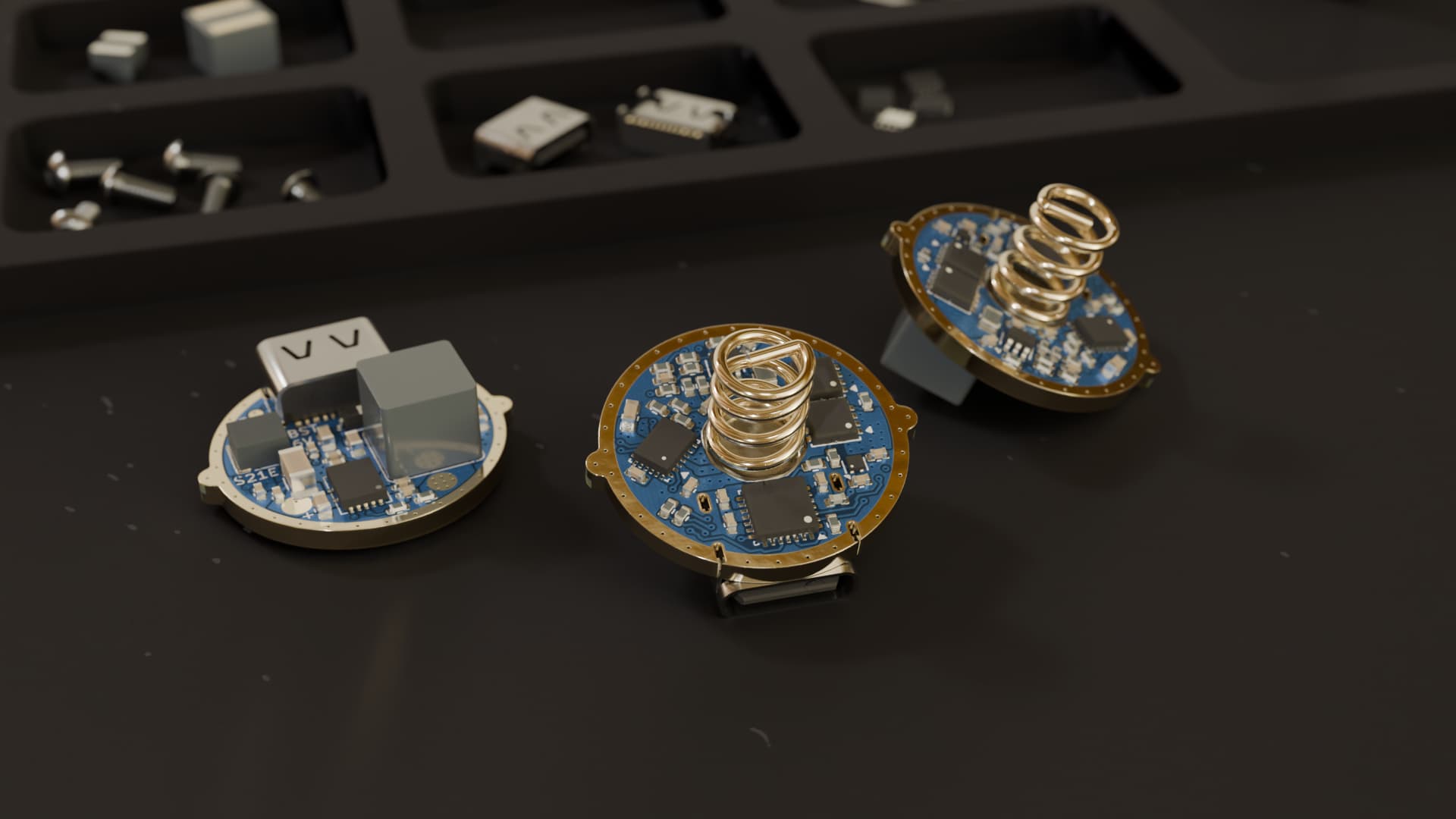
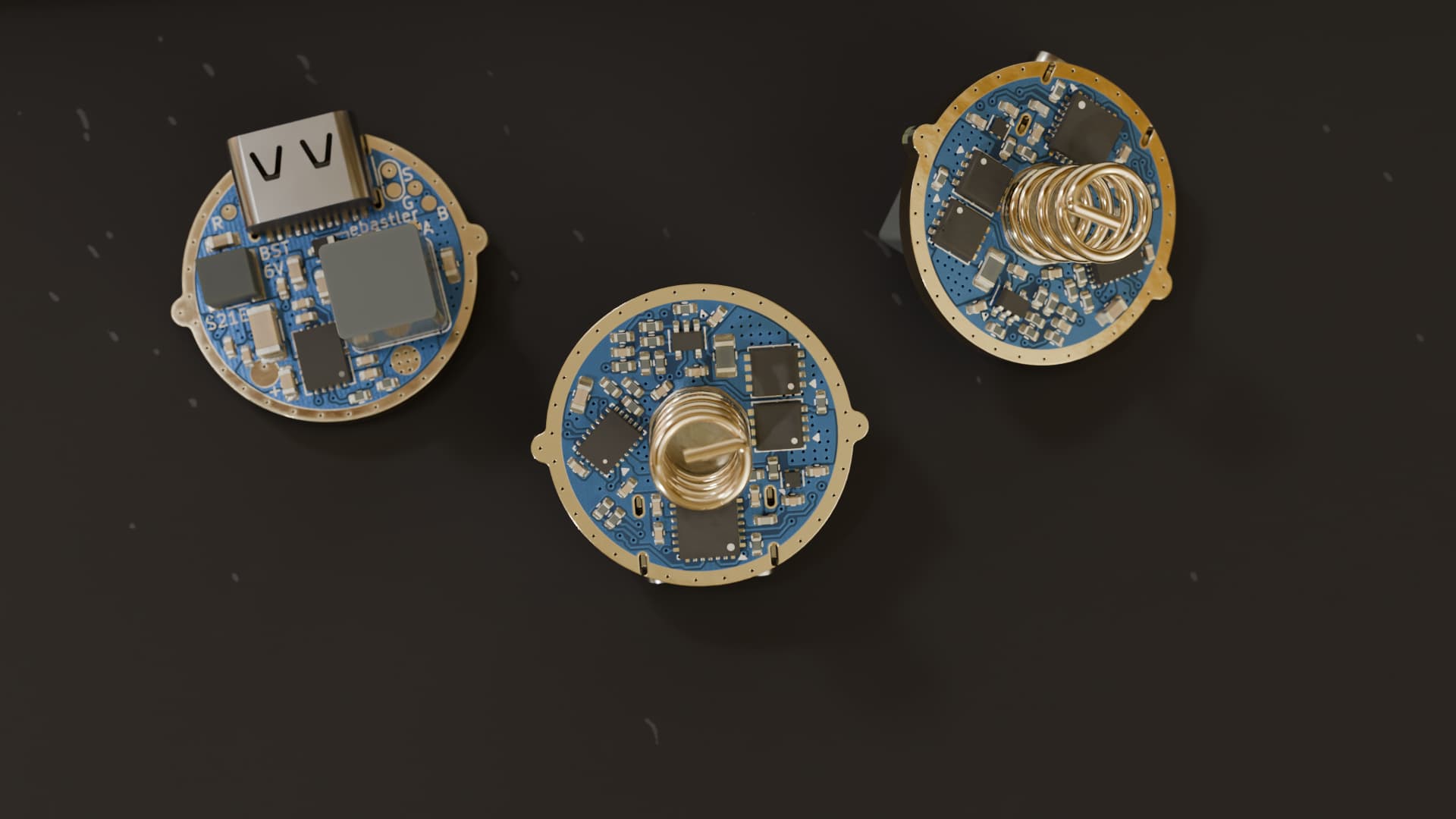
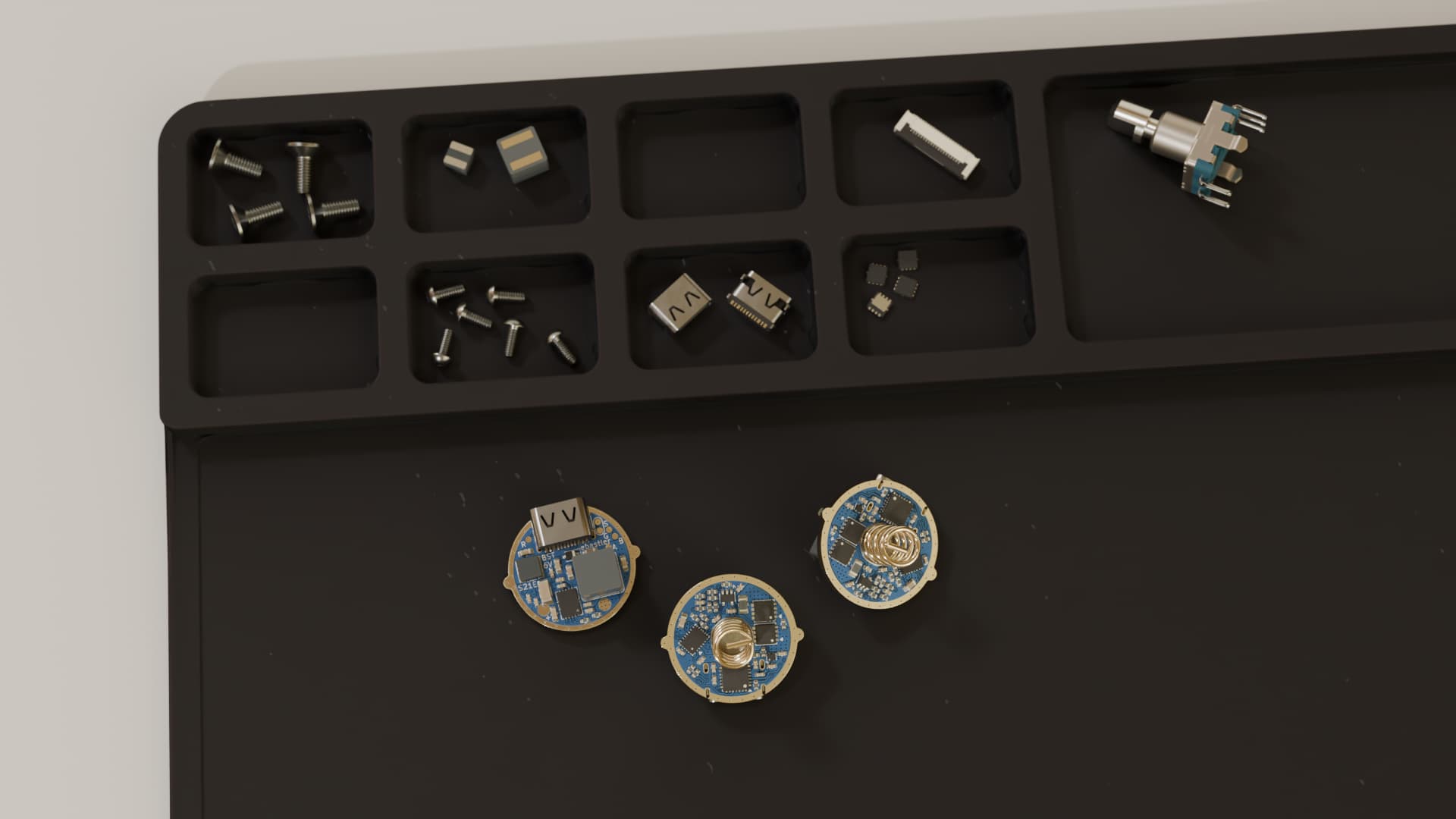
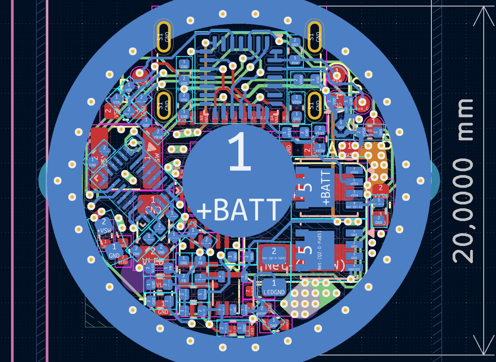
Found the time to post some more info about this - it is a replacement driver for S21E, as koef3 said. It is a 6V 5A boost driver which improves over the OG in a few ways:
15W buck battery charging (as opposed to 1A linear)
15W powerbank functionality (no such thing on OG S21E)
RGB AUX (pads are tiny, though, so enjoy soldering them lol)
HDR driver with 2 shunts for proper moonlight
Inductor and RPP MOSFETs picked for as low as possible IR for maximum efficiency (as far as possible while sticking with easily and cheaply available parts for production)
STM32 MCU which can be programmed over USB without any dongles or tools (remove battery, hold eswitch and then plug in to enter programming mode).
Since this is an entirely new MCU in the flashlight world, and I need some features that did not exist before (interfacing with the battery management IC), it’ll be a fresh firmware from scratch, focused around making use of the USB port. I plan to port most of the Anduril shortcuts and features, as that is what people (incl me) are used to, but it will not be as configurable, and it will not have as many features. At least I am not planning to just copy it over to a new MCU, and change a few things to make it distinct. But that is in the future. I am currently doing some final check-ups, then will send the first batch into production. Thanks to my new job I now have the money to prototype without saving up for months
The MCU and battery management chip are shared with the opencharger project, which I have neglected for a long time now - therefore any firmware development done for this PCB will benefit the opencharger, and the other way round.
As most of my projects, the driver will eventually be open sourced, but I want to have tested hardware and a presentable software before publishing anything.
I just decided to change microcontroller from a STM32F042 to a brand new STM32C071 - same package/footprint, but >5x the flash, 4x the RAM, and better peripherals/IO. On the downside, the USB stack of it seems to be a bit of a mess according to other people right now, but I think that will improve over time. In return I get enough space for all sorts of firmware shenanigans and features. Especially important with my ideas regarding live settings remapping via a desktop app.
This also means I can map the aux pins to timers - not sure when I would need that, but hey. Maybe some fancy aux led animations eventually.
The redesign was a full success - took me quite some effort, but I am way happier with the design now.
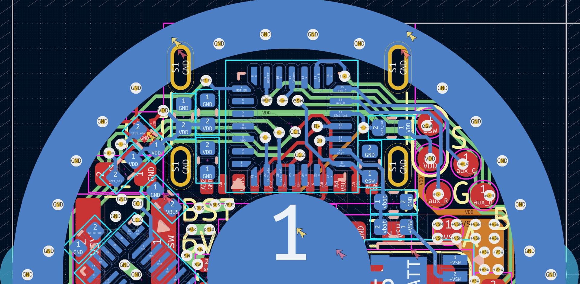
All aux pads are now next to each other
Less weird trace loops
Less trace mess = more space for wide power planes on inner layers
New MCU has way better peripherals - now all aux channels are on HW timers for animations and stuff without bitbanging
Connected i2c2 interrupt pin from the battery charging chip, so it can wake the MCU up when a USB supply is connected without the MCU having to directly check for VBUS voltage
Sadly I missed the window before CNY to send it to the fab. Oh well.
How accurate is the rendering? Clearance seems tight between the positive terminal / spring and one chip. Shorting out Fireflylite drivers are still fresh in my mind…
Yeah, that doesn’t look like enough clearance. I’d keep at least 1mm space around the spring (I guess it will have pretty bad tolerances anyway and you need space for soldering). With this design, a cover for the parts seems also mandatory. Or use a post instead of a spring (or high current pogo pins!).
Will be something custom, made around the hardware features of this light (and two more planned, maybe upcoming ones). The most annoying part of this for me Also the biggest learning experience, however. Hardware design I do for a living. Software design, not so much. Lots of room for improvement.
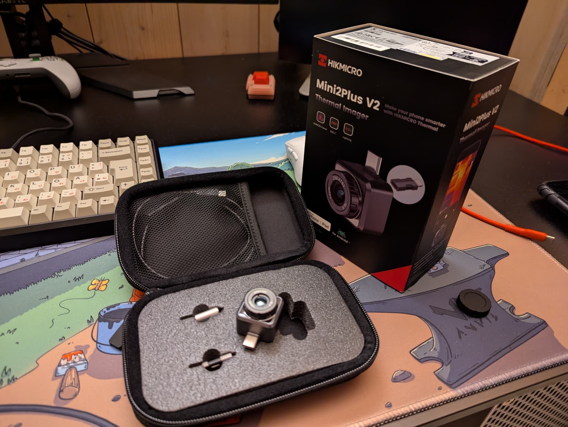
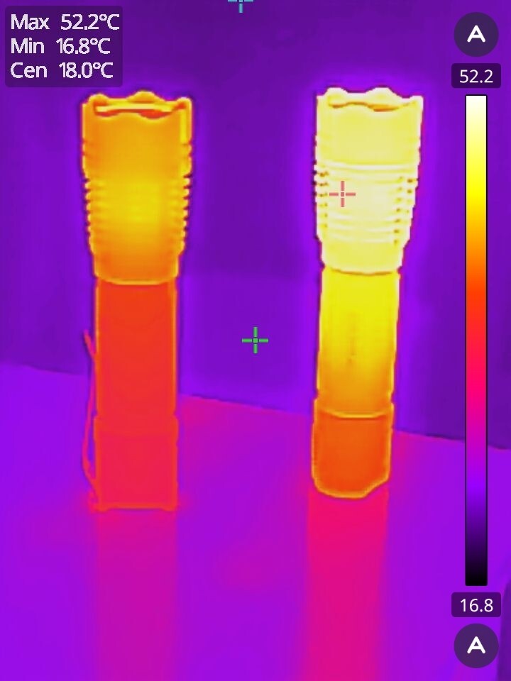
I bought myself a thermal camera, Hikmicro Mini2Plus V2. Very small, manual focus, 10cm min focus distance, 256x192px, 25 frames per second, and pretty solid accuracy (±2°C or ±2%, whichever is higher).
It’s a fun little device. Mainly bought it for PCB debugging, but it’s interesting to see just how hot a flashlight gets as well.



 Looks like AI generated