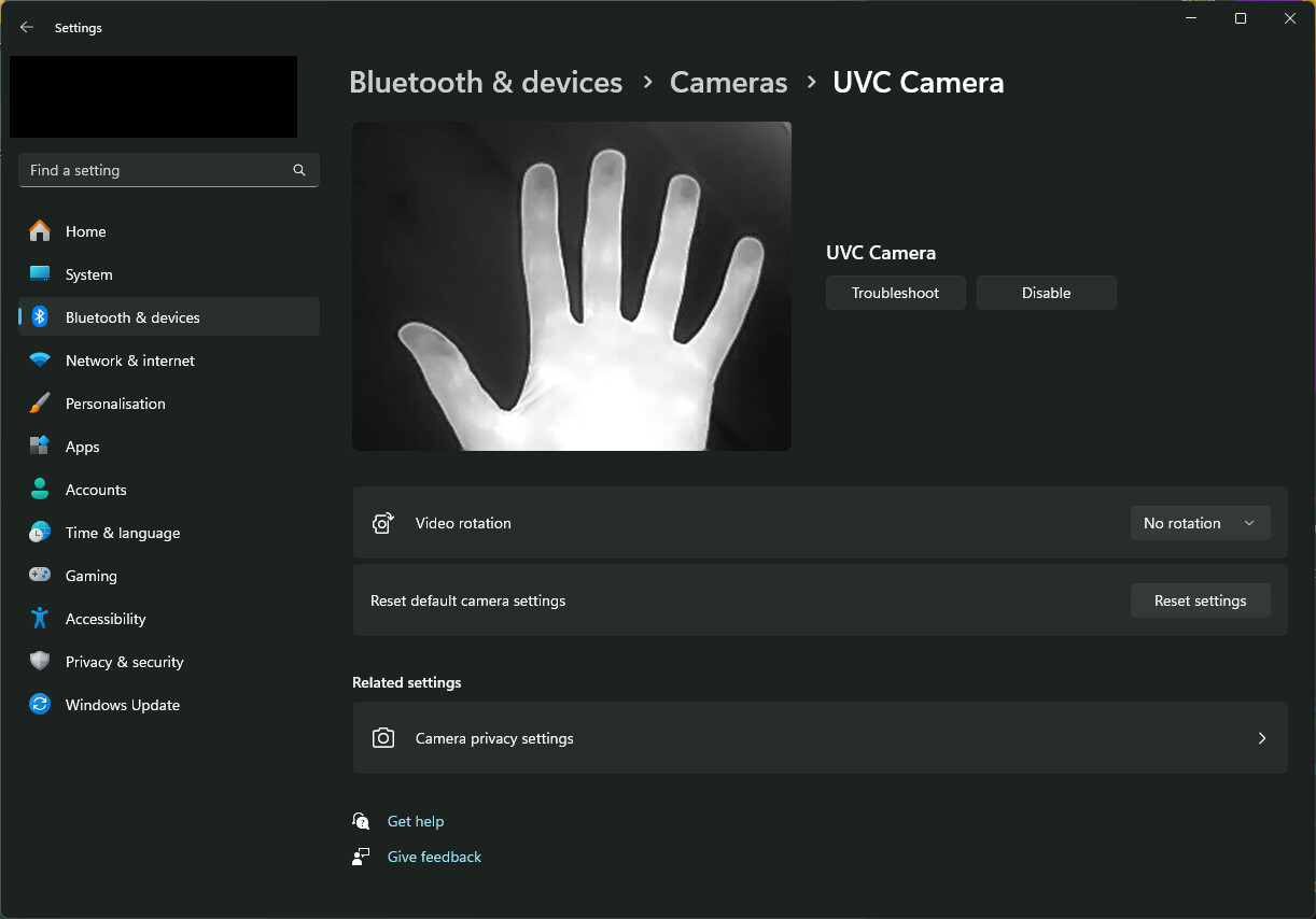
It is recognized as a generic UVC cam by my computer (no software/drivers installed), and the built-in self calibration still seems to work, as does all the auto settings - but I have no clue if it also streams the calibration data over somehow (in an accessible/maybe standardized format), so you actually know which pixel brightness level equals which temperature. Otherwise it is pretty useless.
EDIT: Some googling told me that (at least at the time those posts were written) some bug in Linux’ UVC handling made the predecessor of this camera unusable with FFMPEG (or any other tool) on Linux, and you had to manually change some parameter: https://forums.raspberrypi.com/viewtopic.php?p=2258112#p2258112
Others on reddit encountered the same issues with other hikmicros. But seems to be an easy fix. I have 0 experience with UVC on Linux, so can’t really judge what this stuff implies.
EDIT2: This could work, but I’m too lazy to grab my Linux notebook that sits in the workshop… May try some other day.
I tried to get the software working on my workshop notebook, but I couldn’t get it to compile due to some path issues with openCV - not sure if I am too dumb for Suse or Suse is too dumb for me. I keep having the strangest issues with that OS (abysmal wifi signal and no 5 GHz and WPA3 is one of them).
I’ll probably go back to my trusty old Arch on this notebook and try again. I’ll be home by evening (it’s morning here rn) and see if I find the time.
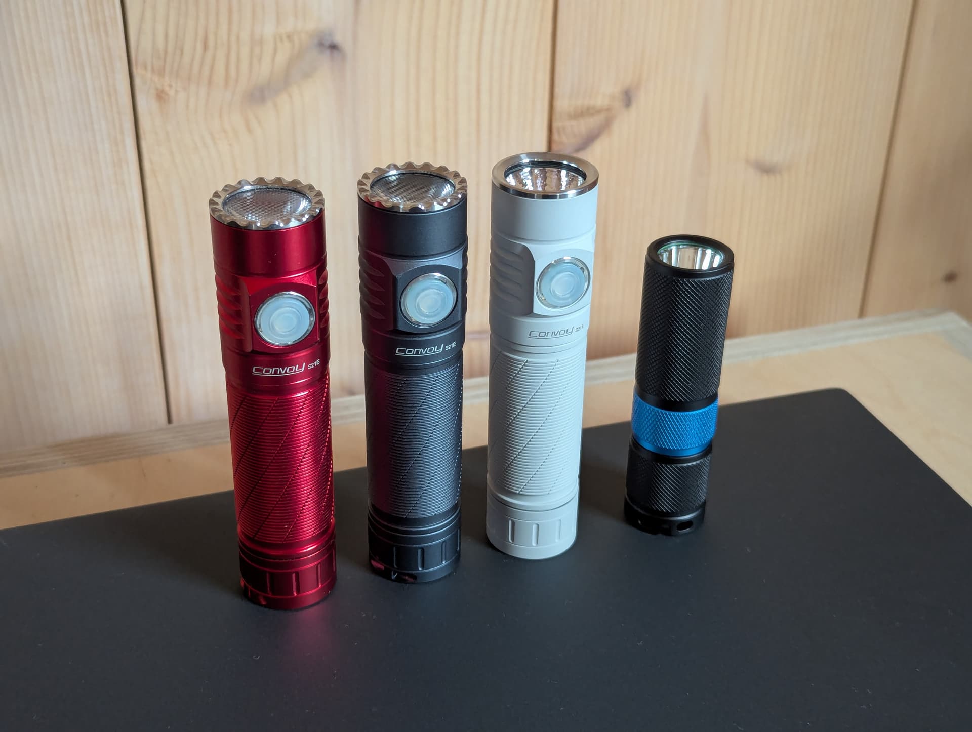
I got some new S21Es for testing my driver once it’s done. The red one I’ve been using for a while now. 50.3 HI R70 3000K. The MAO is for my partner, 50.3 HI R70 4000K. The gray one is for myself, B35AM 3500K. Mine both use pebbled TIRs. Still have to decide if I give my partner a TIR or a reflector.
On another note: I realized that the retaining ring has tighter clearance than the exposed metal on Simons driver which I used for measurements… This means I’ll have to move and reroute some parts of the spring side of the driver to make it all fit. Annoying but not the end of the world. Every place where it’s critical I have some wiggling room still.
Different firmware for different LEDs. The driver has a sufficient dynamic range that cutting off 50% of the max current shouldn’t matter too much. For later batches I may consider a different shunt.
Once it’s prototyped and tested, the whole thing will be published on GitHub. Before that I’d rather not, sorry! I don’t want to share potentially not working stuff.
I’ve still got one itching question, though: STM32C071 can’t go higher than 4 volts, so with li-ion power, it has to be powered through something like a 2 volt LDO. But the USB peripheral wants at least 3 volts to work properly. How it’s handled? Just two LDOs for different power sources, or is there some trick I don’t know?
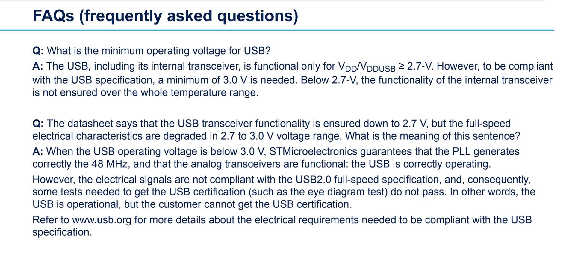
The USB full speed transceiver functionality is ensured down to 2.7 V but not the full USB full speed electrical
characteristics. These are degraded in the VDDIO2 voltage range from 2.7 V to 3.0 V
No clue what that means, exactly, but I’m about to find out… I am not pushing any large amounts of data anyway… We’ll see.
Yeah, which should not be an issue for full-speed communication with reasonable quality cables - less voltage swing means less difference between a high and a low signal level, but 2.8V is still in spec for a high level (2.8 - 3.6V by spec, most hosts will be able to work with less). I think I should be fine, as long as a reasonable quality and not too long cable is used for data transfer.
Especially since USB2 high speed PHYs work with 360-440 mV of logical high, and pretty much every modern (aka from the last 2 decades) hub or computer is HS capable - therefore a FS communication with less than FS voltage should in theory work fine.
But I have to verify this experimentally before I can be sure. I don’t have much experience with how exactly USB data works.
From my days of playing with AVR V-USB I recall that it’s also very important to have the correct pull-up tied to D+ or D-, if it’s wrong value or tied to wrong voltage, the device won’t get detected, as hosts test for specific current to flow. And the infamous most popular V-USB design used zener diodes to bring down D+/D- lines from 5v to 3.3v: most people did not account for current leakage on these diodes, and produced devices that won’t be detected by some hosts. This has earned V-USB a reputation of somewhat unreliable thing, but it’s the out of spec schematic that was wrong. Powering entire MCU from a 3.3v instead of diode tricks made it run fine.
But… I don’t think it applies to your case! I’ve also found a bit of explanation from ST:
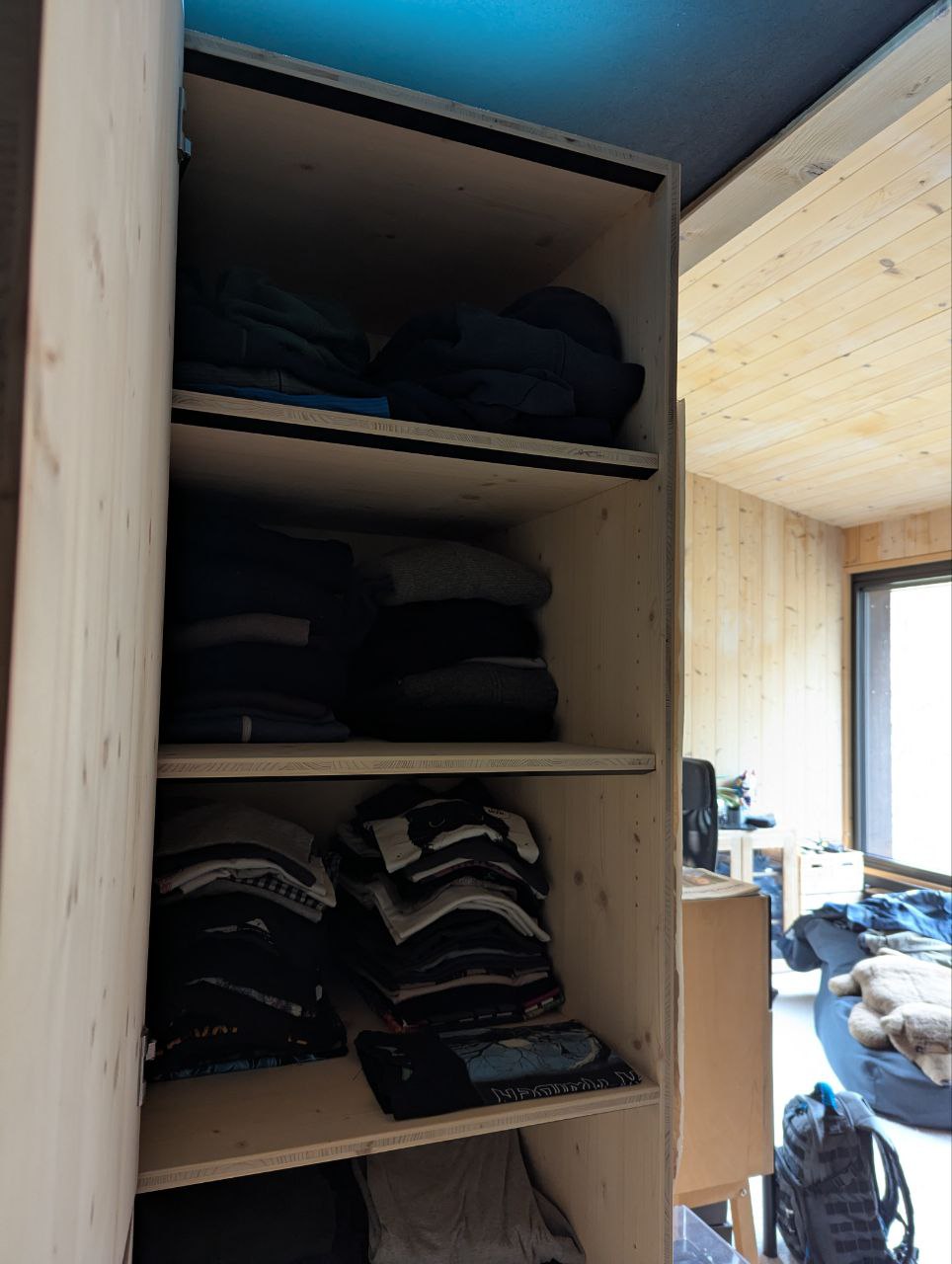
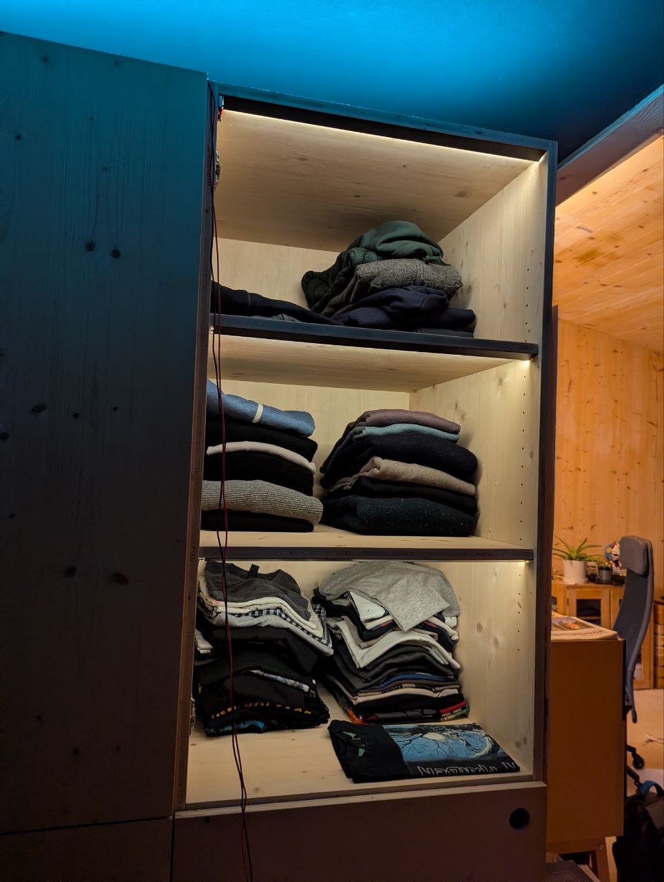
Finally some progress on this project - I was too lazy to put the stripes into my wardrobe for the longest time
For now they are running off a 20V Lenovo PSU just for testing, they are not wired up to the 24V LED controller on the top of the wardrobe yet. Should get quite a bit brighter still.
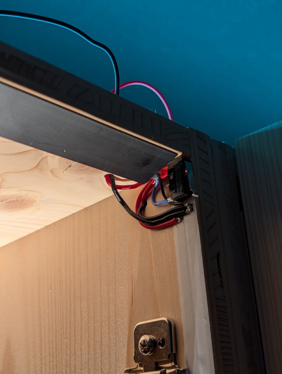
Basically, the 24V PSU is switched by the lightswitch next to the wardrobe, and next to the bed. It powers WW/CW + RGB stripes on top of the wardrobe (usually set to ~4000K tint mix) and the stripes inside the wardrobe. In addition every door of the wardrobe has a microswitch that turns on all stripes in that compartment.
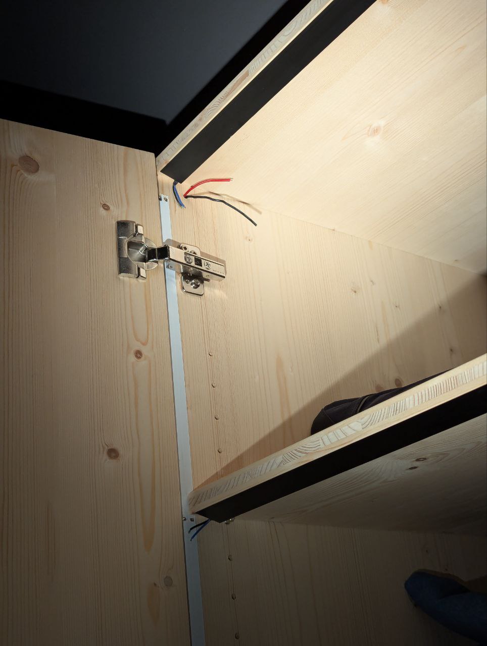
Pic 3 shows the stripes mounted but not yet wired, as well as the flat ribbon cable I bought to get power from top down. Not the prettiest solution, but the only practical one I could think of. Pic 4 shows the messiest part of the wiring - the upper center door supplies both the stripe inside, the lower door through the ribbon cable, and upper right door through a hole in the wood. I did my best to keep it somewhat tidy, but could not do it any better. Maybe I will 3D print a small cover for the wiring, or maybe I’ll just leave it as is. Will see. It’s at over 2m height, so well out of sight unless you specifically look for it.
I’ve been toying with the idea to build a portable WLED enabled high CRI RGB+vCCT bar combined with addressable RGBW tape, commercial controller options are less than ideal and i’m too busy with other stuff to design my own (and never actually finish it due to feature creep) so you’ll probably beat me to it!
The controller is up on GitHub, designed around what JLC has to offer. No built in support for 5V addressbles, however. It does expose some GPIOs, but I did not expose the 5V onboard Buck. Might be an idea for a new revision some day, but that would also require a much beefier buck - this one is just powerful enough for the MCU.
 , thanks. They probably mean the voltages on D+/D- lines are going to be lower than the spec requires them to be.