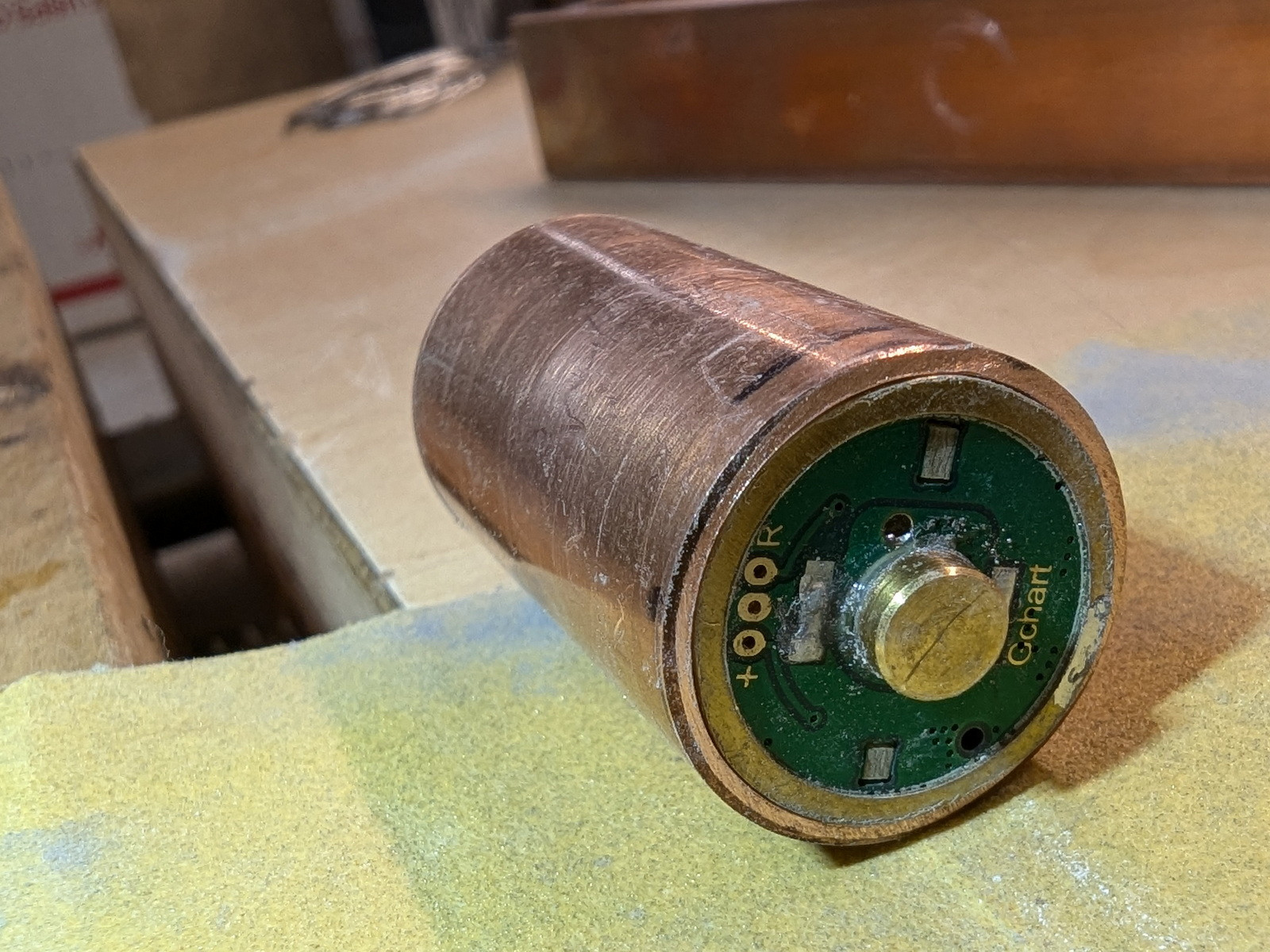
OK. How to cut the short lengths with a tubing cutter? Sometimes in my OCD desire to not waste materials I must admit that I make tasks more difficult for myself. I gave this a little thought and came up with a couple of ideas. I decided on one and proceeded.
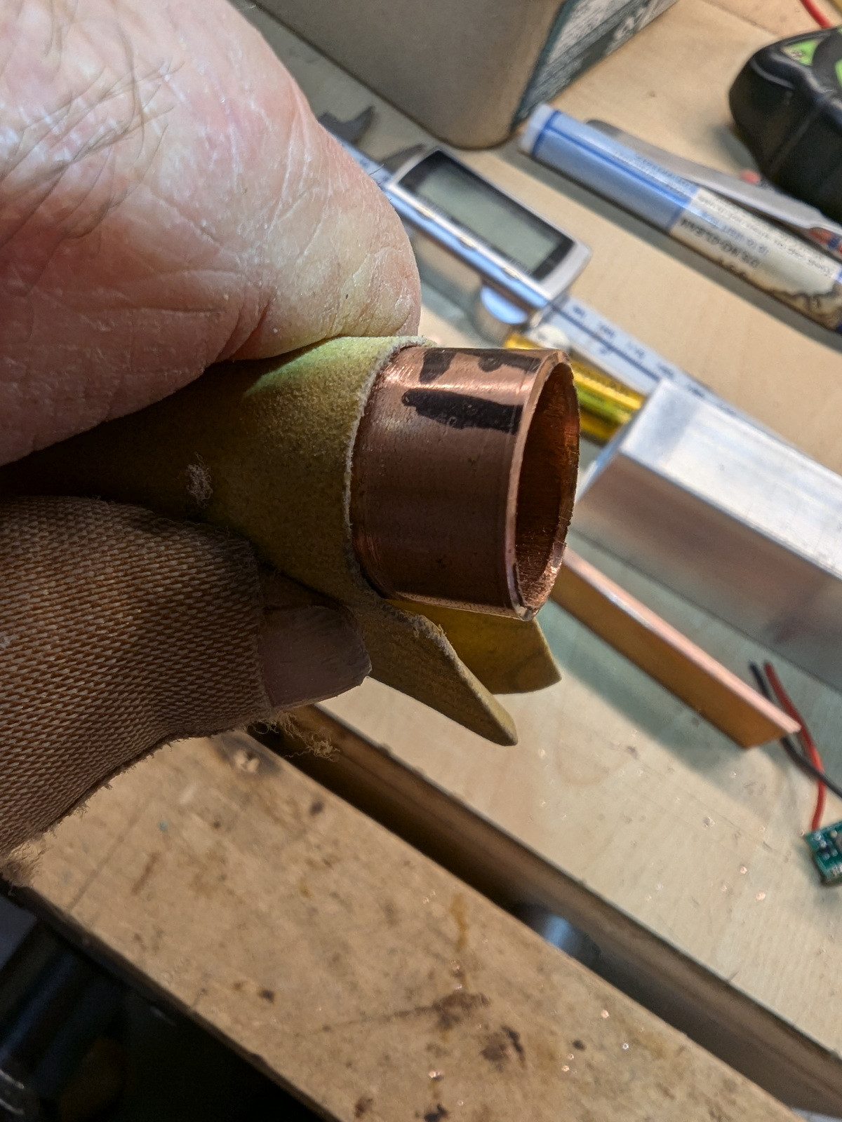
I found a drill bit that was a snug enough fit inside the 17mm tube that it gripped the tube and allowed me to rotate the tube in the cutter.
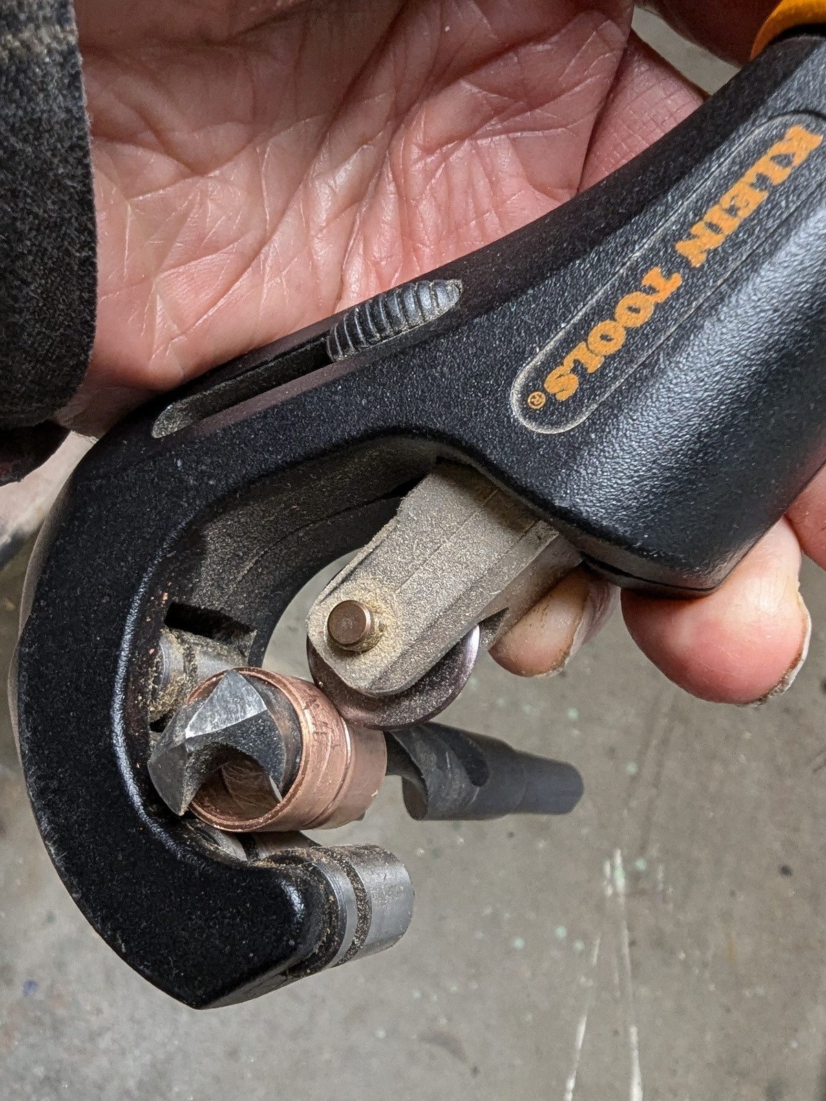
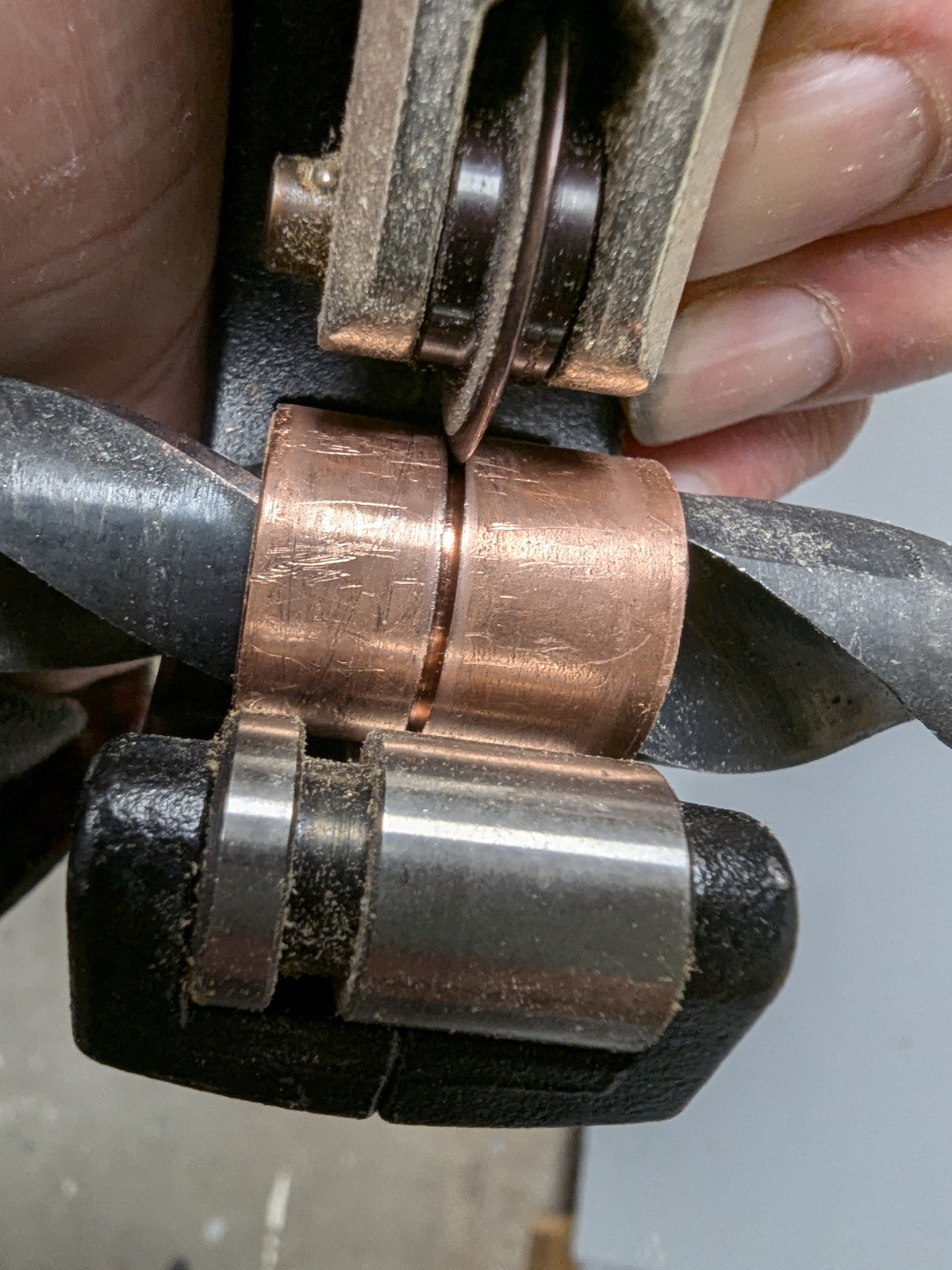
I was able to turn the copper tube in the cutter if I very slowly adjusted the cutting depth a very small amount at a time. I cut almost through the tubing. I didn’t want to damage the cutting wheel on the hardened drill steel. I used pliers to twist the tube off the drill and the twisting torque separated the two pieces at the cut line.
(another thought was to insert a tight fitting piece of dowel inside the copper tube and use that to turn the tube. But I didn’t have ant dowel on hand that was a close enough fit.)
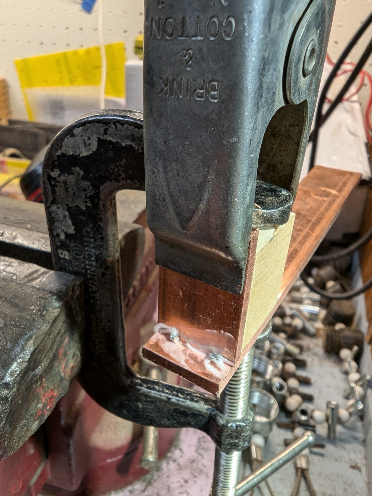
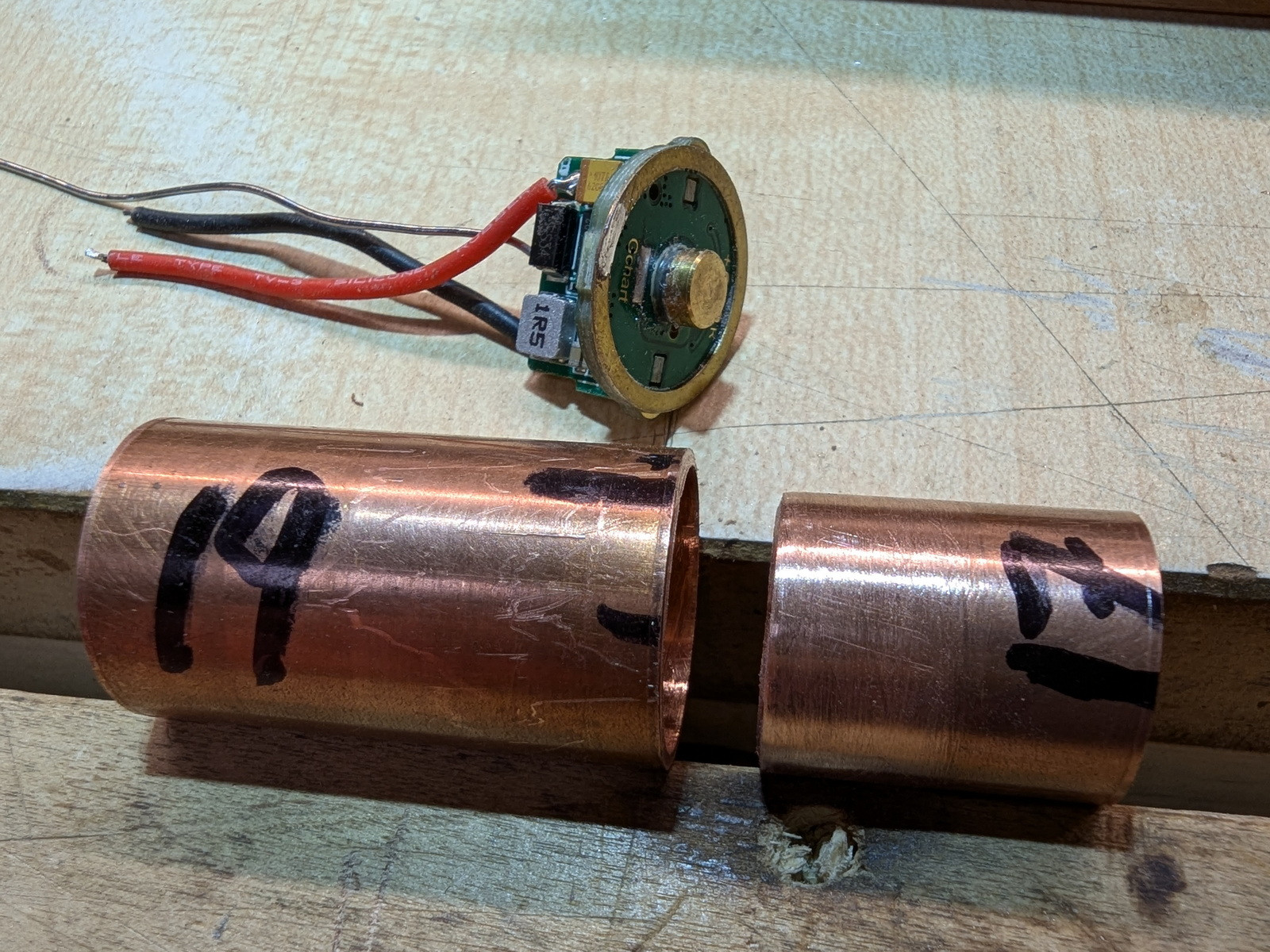
With the two short lengths of 17mm and 19mm copper tube at hand I assembled the driver mount. The 17mm was slipped inside the 19MM. I used a wood dowel as a drift to slide the 17mm piece to the proper position. The assembled pair was then silver soldered to the carrier. Lots of clamps were employed to prevent anything from falling apart as the work was heated. I used a pair of butane torches to speed the job.

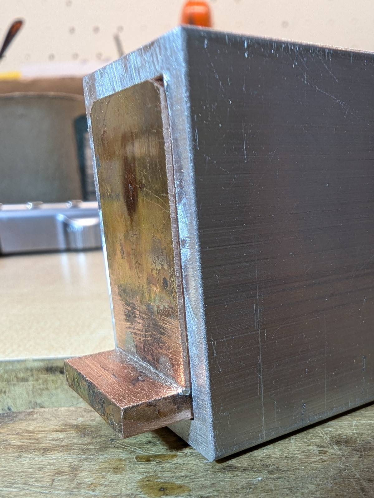
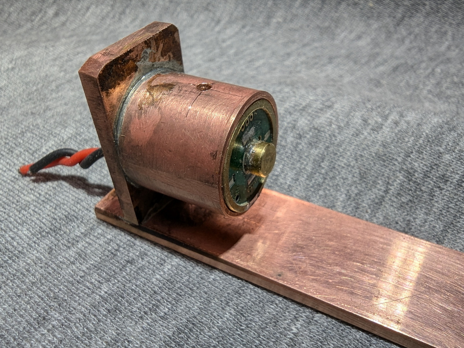
After cleaning up the carrier a bit this is what it looks like.


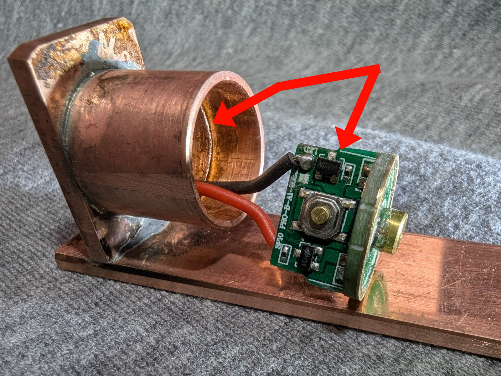
Here’s an explanation of how the copper tube mounts the driver. The 19mm OD tube section is 17mm long. The 17mm OD tube section is 8mm long. Look at the photo below; the 17mm tube is pressed inside the 19mm tube. One red arrow points to the ledge formed by the 17mm tube inside the 19mm tube. The other red arrow points to a step in the side of the driver tab that is fixed to the round part of the driver. The step fits against the ledge when the driver is inserted into the 19mm tube. Two small blobs of solder will be used to secure the negative ring of the driver to the 19mm copper tube.
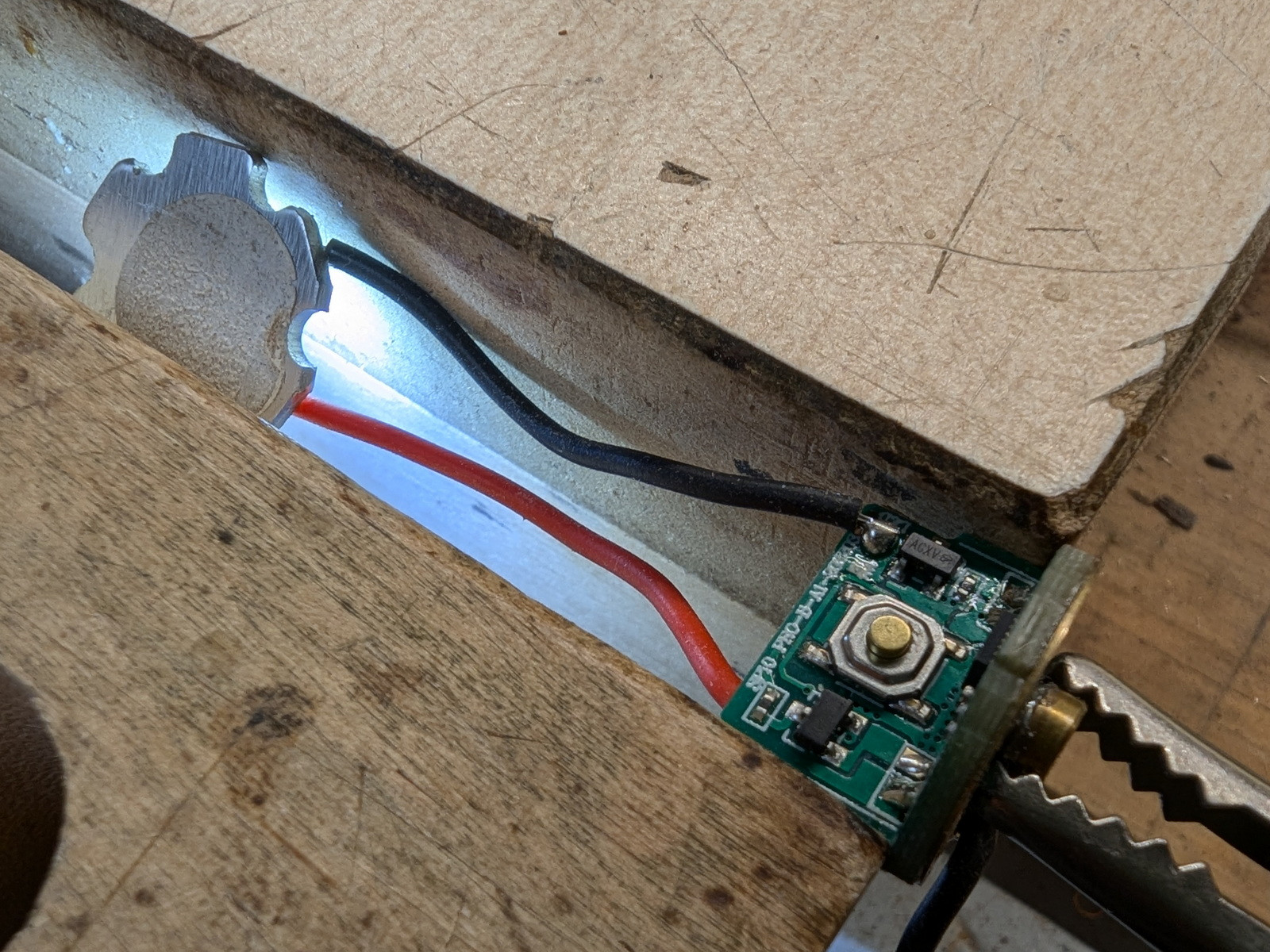
The driver will be secured with the e-switch mount located horizontally. A pilot hole has been drilled in the side of the 19mm tube. The hole aligns with the switch button and will allow actuation of the switch via a push-rod through the hole. The driver will be secured to the mount with two solder bridges from copper mount to he driver negative ring.
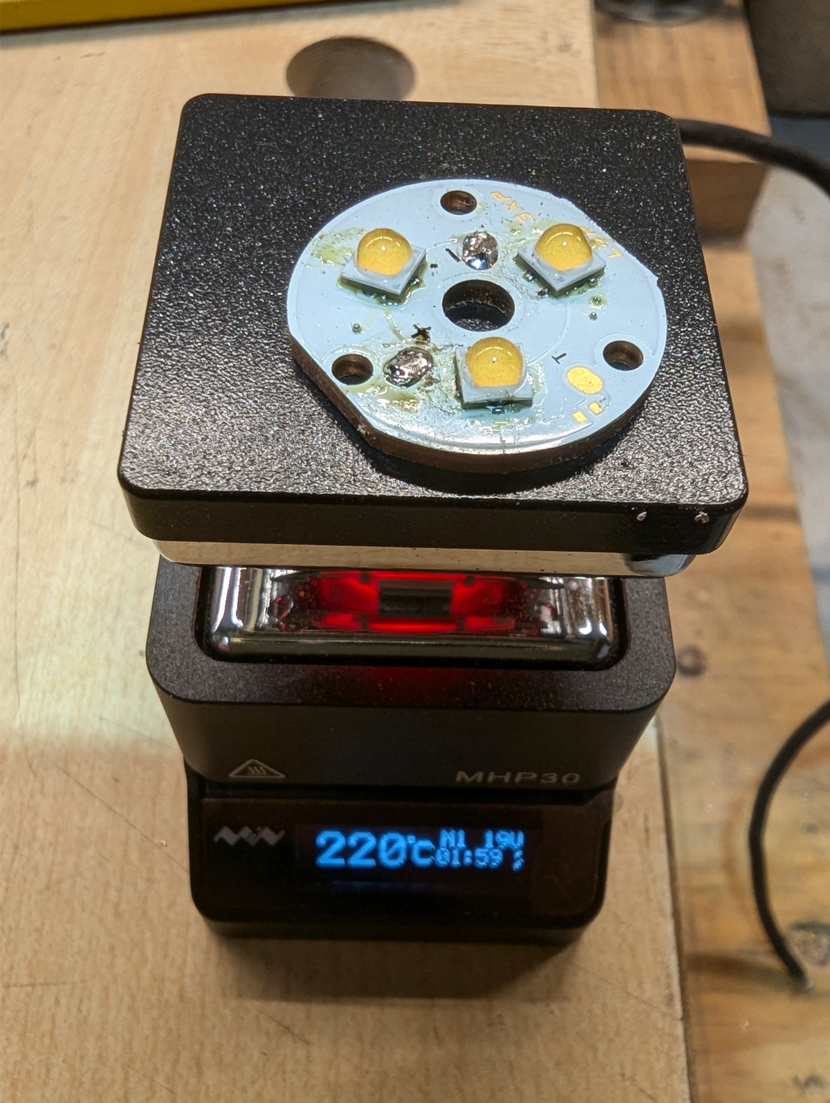
I decided it was about time to flow the 3500K 519A emitters onto the triple MCPCB. I used my MHP30 mini hot plate.
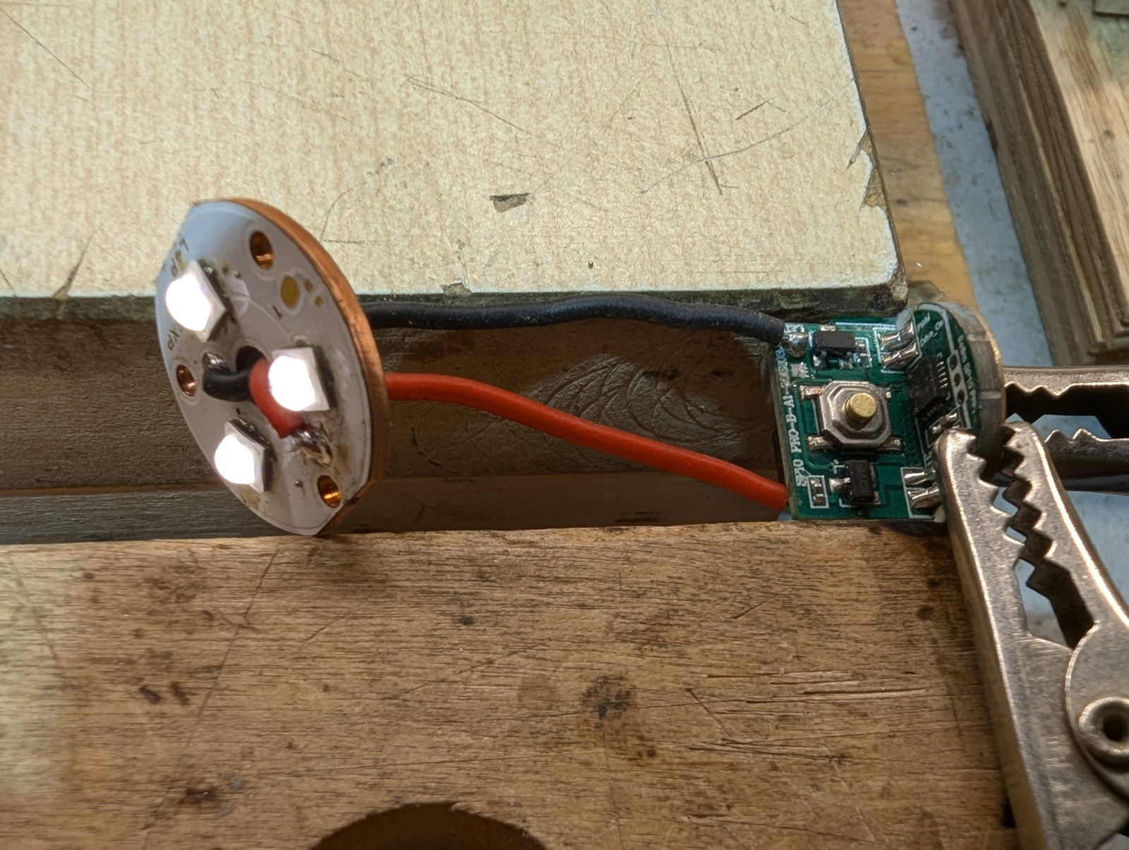
After the reflow I once again checked the operation of the driver and MCPCB together. They work.
A wood (maple) spacer was made from a scrap. This will mount on the upper surface of the driver mount to hold and guide the switch actuator pushrod. I marked the position of the hole on the maple block with a short piece of pencil lead.
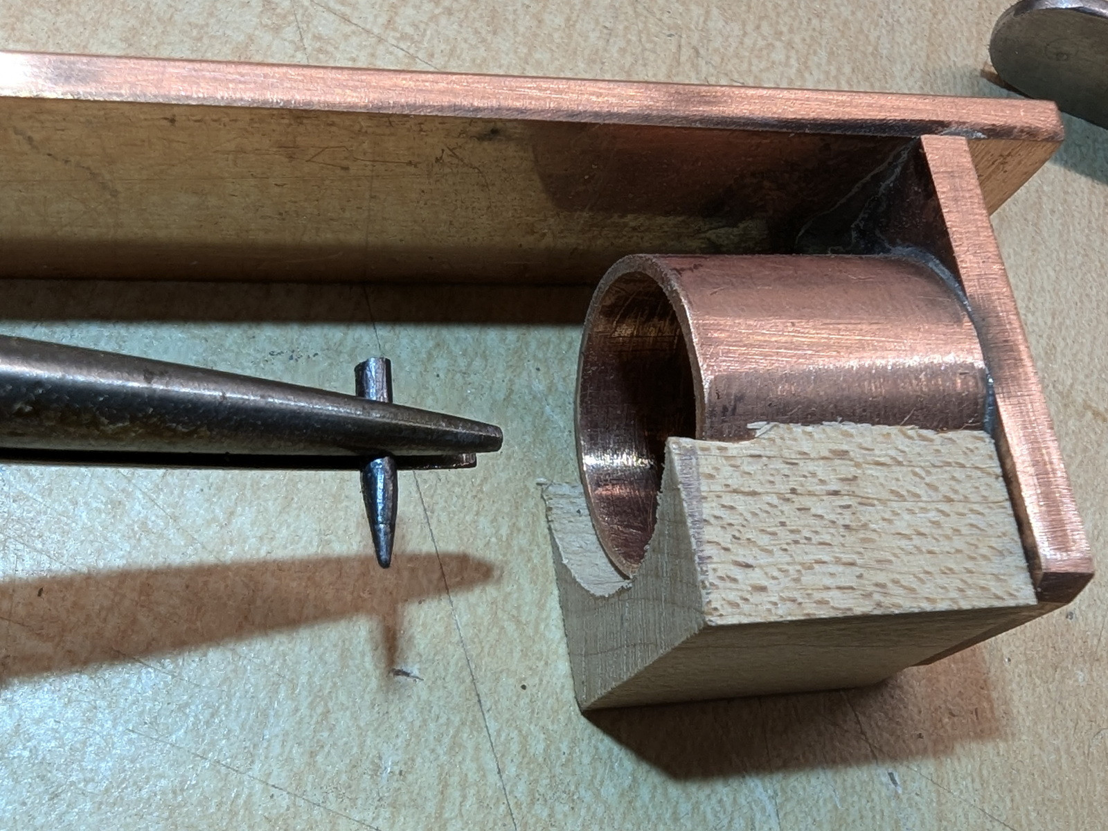
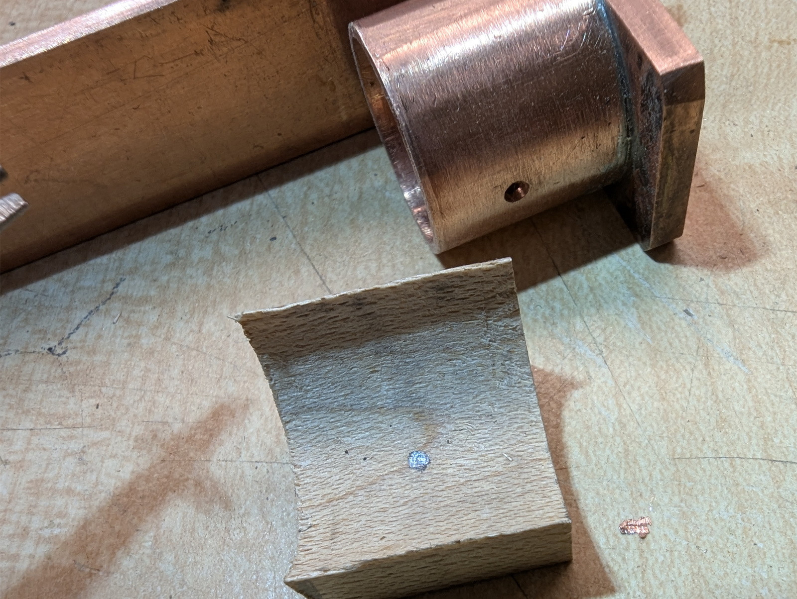
Then I drilled through the wood block and copper sleeve with the pilot drill bit…
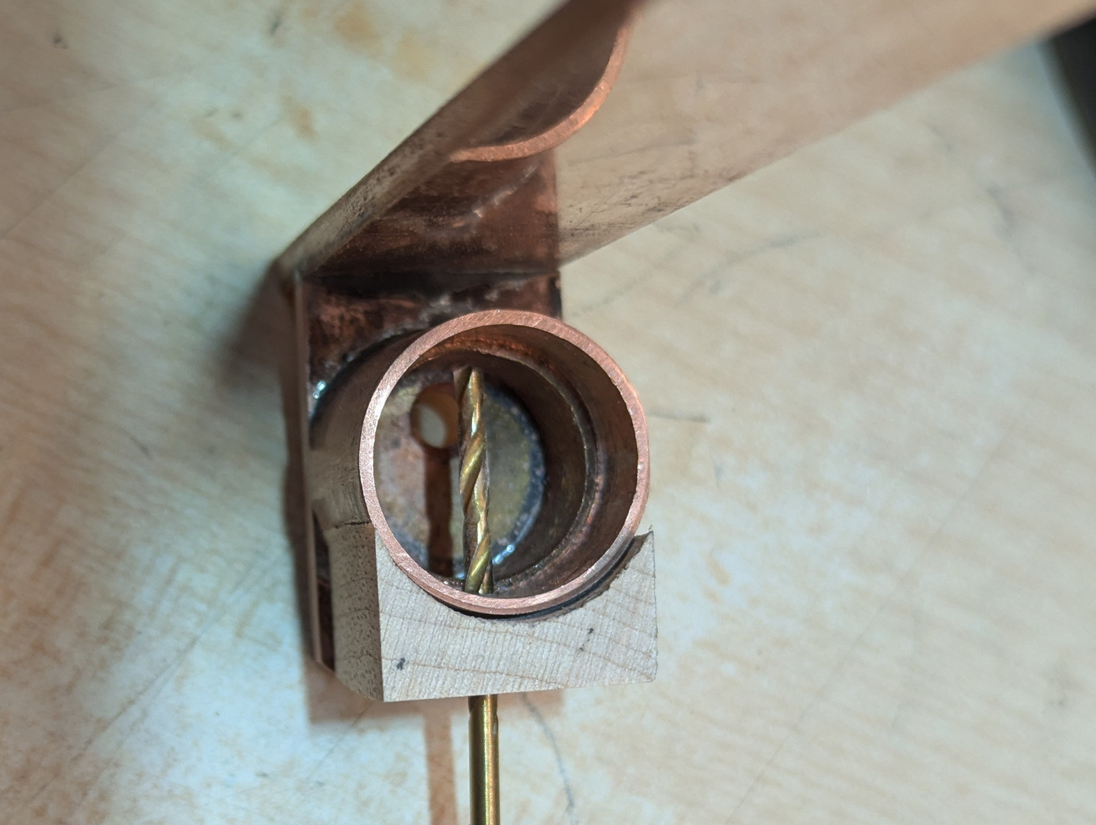
Next I enlarged the holes using a 9/64 bit and trial fitted a piece of 1/8” dowel as a pushrod.


Thanks for looking. That is all for today.

 I usually learn something too.