[finished] Ruckusmattster’s 12th Annual Old Lumens Challenge Entry - Hand Made

A 9Mcd 20k lumen Short Arc Mercury searchlight

youtube video:
github: GitHub - ruckusmattster/searchlight
entire photo album: https://photos.app.goo.gl/rBuQnaPYmjDiugSS7

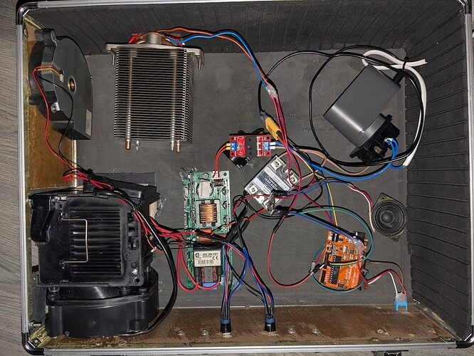
this project utilises a range of scavenged parts to create a fully mobile searchlight featuring: a main channel throw light, auxilary side light, speaker for sound effects (currently ghostbusters theme song), a forty minute runtime, and 6km of throw.

short overview through photos:


9 Thanks


Here’s a sneak peek at some of the electronics i used, I’m waiting on a rp2040 and some relays which i’ll use to switch all this on and off safely.

can’t wait to share what I’m doing with everyone!

5 Thanks

10 kilometres?! That will be an absolute beast when you get it going! Will you be using some kind of LEP module or short arc lamps? That kind of throw seems out of reach for typical flashlight LEDs.

1 Thank

@HunterJackson It’s certainly shaping up to be a beast! I’m planning to use two short arc mercury bulbs—one is 150W with a elliptical reflector and the other is 250W with a parabolic reflector. The elliptical one should work well paired with a 40cm Fresnel lens, and the parabolic can’t be focused further, but it should still reach around 6 km with about 20,000 lumens.

I’m still figuring out the best enclosure setup. I’m debating between putting the lead-acid battery and inverter in a backpack with an umbilical leading to a handheld wooden/plastic unit, or putting everything into one large handheld box. Open to suggestions if you’ve got any!

3 Thanks

A good padded shoulder strap is a reasonable solution up to a certain weight. Beyond that there are harness systems such as a trimmer / brush cutter harness, which is designed to carry a load on one side while distributing it to both shoulders. If you want a system built into a backpack there are a lot of options, including military surplus pack systems, and plenty of other ones from hiking / hunting outfitters. There are external frame packs a.k.a. pack frames, internal frame packs, and frameless backpacks.

2 Thanks

good to know, i wasnt looking forward to carrying 50+lbs in a unpadded bag. what about the handheld unit, ive got a rp2040 and relays to safely switch everything on but i dont know much about hand building enclosures. id usually 3d print it

1 Thank

gonna upload the past week or twos progress in one post. im building a UHP searchlight, i have a 1.1mm arc 250W parabolic model bulb


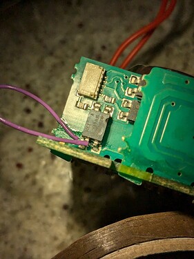
i spent a while reading documentation to figure out which optocouplers are inputs and which are outputs. once i figure out which two were inputs i tried looking where the pcb connected them to, on a hunch i chose this one to short and it was correct. shorting it is the same as applying power to the input and simulates how the controller would signal to the ballast to turn on.


originally i tried using a spare power supply but it was too much effort to figure out and i couldn’t get a proper output voltage from it, it must require some signal to turn on. instead i built my own supply.


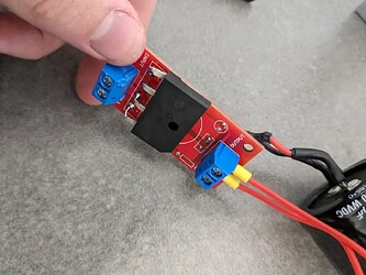
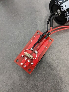
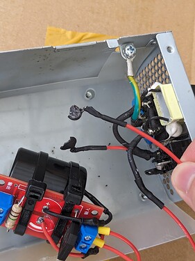
this is a full bridge rectifier pcb i had spare from a past project, everything was broken so i replaced the capacitor and rectifier and added a 1Mohm bleed resistor. the capacitor is 470uf 400v and the rectifier is some spare i had in a drawer. i initially used a different rectifier which was internally shorted, i spent ages trying to diagnose it and thought the issue was inrush current so i purchased some ntc current limiters. these all exploded as the short hadnt been resolved. ive included a photo below

i tried building this inside a dell pc psu case as i had planned on it being a “inline” style psu for a stationary bulb unit. but ive since changed and will mount everything inside a correx (maybe) box inside my final enclosure.

the bulb unit im using came with a large 12v blower fan already attached so i wired up a 500W dell server PSU i had spare, it will also power my rp2040 and relays. i could’ve used something smaller but this is what i have on hand, i found it in a dumpster.

in the coming days i will power on this unit, then i’ll get started on building the enclosure. i tried powering this off a UPS initially but the UPS refused to deliver power with the unit plugged in, it did work for a desk fan so i think the issue might be its drawing more power than its rated for. anyone know if i can salvage the components from the UPS? I’m just hoping to turn 12VDC into 240VAC, if not i’ll just buy a inverter instead of my spare UPS.

I’m still in the early stages so I’m open to any suggestions or criticisms.

2 Thanks


heres a sneak peak at v2, i call it that since itll take me longer to complete, its being worked on at the same time as v1 though. thats a 150W 0.8mm elliptical bulb and 40cm fresnel lense. its not yet working but if the old CPF posts are anything to go by im hoping for a 20-30km range :yum:

4 Thanks

This kind of construction may be viable for this kind of build:

You could make a cover out of canvas, etc.

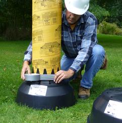
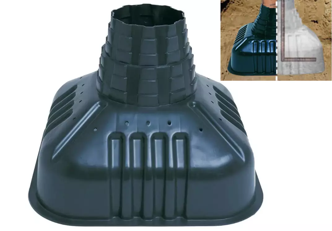
For the body, concrete “form tubes” are inexpensive and available at hardware stores in many different diameters. They are made from solid cardboard material. A “redibase” concrete footer form will slip right on to a form tube, but it might be a bit large or improperly shaped for this project:

redibase

from that image alone i really like it, i have some polyurethane from some woodwork i did that i could use oevr the cardboard just for peace of mind. and that foot on the second photo looks ideal for a lens possible, if the universe allows it, then the focal length might even line up with the part already.

ill definitely look into those metal tubes for the parabolic bulb, im still a fan of something square so i can set it down, but i might just build skids for the metal tube, then it could be set on the floor without rolling

1 Thank


plugged it in, now we got light baby COME ON


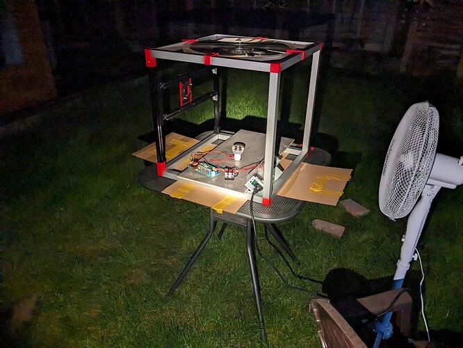
set it up outdoors for a initial test

had the neighbours peeking out the window :sunglasses:

tomorrow ill set it up on a wooden board or something so i can get some vertical shots

7 Thanks

Damn that beam is seriously bright! You will have a big challenge making it portable that thing looks huge

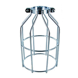
its huge but it looks like the duct on the front of the housing can be removed, its about 15cm high, ill need to leave room for airflow though. i think the metal cage above will be ideal, ill use the tapered side to mount my umbilical cord and the front will have to be a polycarbonate lens with a bulb behind it

1 Thank

got a lot done today
initial beamshots
tested its burning capabilities
measured cd
glued everything to a test rig and pointed it around

ive run into a roadblock though. lemme upload the photos and progress and then you can see what’s happened

2 Thanks

https://youtu.be/p4vvp1kcts0 heres a test with black paper in the beam


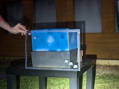
i built a little box fashioned after the minecraft beacon


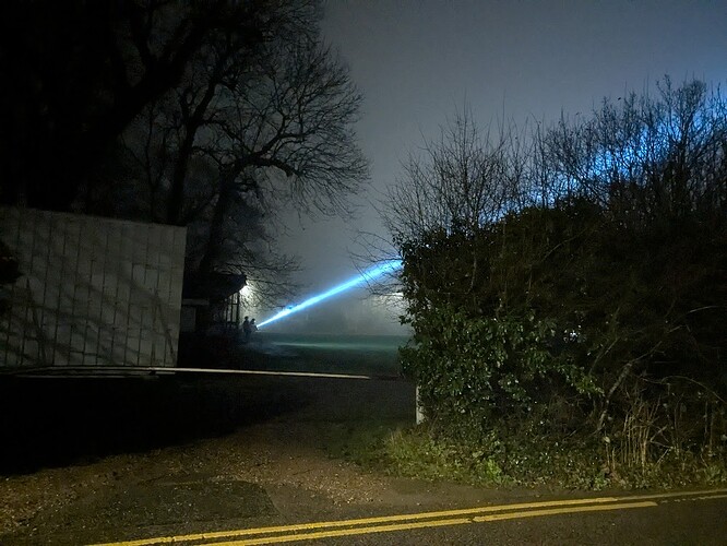
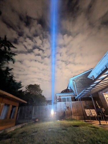
here’s the beacon doing its thing, it’s absolutely insane how bright it is, the camera is almost exactly what I’m seeing in real life


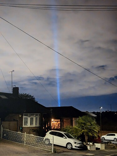
here it is from about 300m away


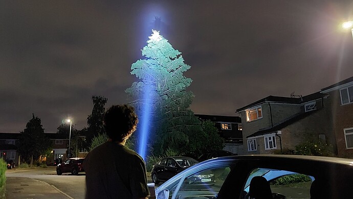
here’s a photo of me holding it while it’s glued down to a tile - bloody heavy - you can see a shadow of the tree on the clouds

i measured 9.2 Mcd @ 10m putting it at 6km of throw, using online lumen/watt values and a watt meter i estimate 17K lumens otf

i’ve been powering it on in short 1 minute stints since i live in a flight path (i check the flight radar before turning on) so I’m itching to get out to the countryside.
the unit operates on 240VAC which gets rectified to 340VDC and smoothed, that’s fed to the ballast. to make it mobile i wanted to use a spare 12v lead acid battery.
the only roadblock is when i tried powering it off a UPS the bulb started flickering at ~0.5hz while heating up, I’m not sure if its the modified sine wave from the UPS causing issues or the UPS lied about its power rating. i’ll have to look for a inverter but my budget is pretty restrictive so it might be a while til i find something, so far i’ve spent £12.

ive had a lot of time since im on school holidays but its ending this week so progress will grind to a halt - im currently finishing up writing a blog style post about the entire project

7 Thanks

That is astounding!

2 Thanks

Introduction

A High Pressure, Mercury, Short-Arc Searchlight. It boasts 17,000 Iumens and 9,200,000 candela. That all probably sounds like word salad jargon, so let me explain what it really means.

Core Components and Their Roles

There are three key parts at play: the power supply, the ballast, and the bulb.

First, the power supply: I built a custom one because l couldn’t find anything commercially available at an affordable price. I used a full bridge rectifier (which converts AC into DC) and a capacitor to create a stable 340VDC supply using 240VAC input (in England we have 240V at the wall). For safety, I used a 1 mega-ohm resistor in parallel to the capacitor to enable it to slowly discharge after use; without that, the capacitor could store enough energy after powering off that it would be fatal if touched. Because of the high voltage, I had to ensure that everything was safe as any poorly insulated cables would pose a shock hazard. I also added an NTC (negative temperature coefficient) current limiter to prevent high inrush currents damaging my electronics.

DIY PSU

photo info 1. the PCB I assembled my PSU around, featuring a rectifier, 470uF 400V capacitor and a 1Mohm resistor on the back

Second, the ballast, it provides the initial jump start to get the bulb working and it regulates power to the bulb. At turn on the bulb can require 40kv to start. I bought the ballast second-hand, for cheap, on eBay. It was actually the second ballast I had purchased because I blew-up the first one during development. The ballast is controlled via the UART protocol and is used to ensure the bulb runs safely.

Finally, the bulb: I used a special kind that consists of a small fused quartz tube with a pocket of inert gases, mercury metal, and two electrodes. When the bulb is powered on, a short electric arc vaporises the mercury and excites the metal atoms. This excitation causes them to emit a wide spectrum of light. A bright 5mm LED typically draws 0.1W; by comparison, this bulb draws 270W, or 2700 times more power in a similar-sized footprint!

bulb

photo info 1. the final bulb I used, in the center is the quartz tube which is close to 5mm in diameter, around it is the reflector

This bulb is incredibly dangerous if mishandled. Internally, it heats up to 1800 Fahrenheit and 3000 PSI (200 times atmospheric pressure) which, in case you didn’t realize, is ridiculously high. The fused quartz tube is used instead of glass because fused quartz can withstand higher temperature and pressure. However, without proper handling and cooling, if the fused quartz tube is overstressed, it could explode violently.

Reverse Engineering and Optics

Normally, the electronics to run these bulbs are full of safety measures (ewww); I spent a lot of time reverse engineering and bypassing these safety measures because who needs those? I bought my first ballast from a repair shop and reverse engineered the PCB. Unfortunately, I very quickly killed it, so went to eBay for another one. With this second ballast, I learned how to isolate the controller from the high voltage supply and how to trick it into thinking a control board was connected. With this better understanding of how the ballast works, I chose to take an online course on high voltage safety training because I didn’t like the idea of dying. I know, shocking right?.

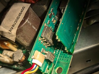
a shorted optocoupler to bypass the safety

photo info 1. one of of the jumper wires I installed to bypass a safety check

Then I moved on to studying the optics. The most common is a parabolic reflector which creates a beam of almost parallel light. In a ideal world, the rays of light within the beam would be perfectly parallel, but small manufacturing inaccuracies and thermal expansion inside the bulb create sources of error, and I measured an angle of 2 degrees on my beam (which later can be used to estimate the spotlight’s size at different ranges). The larger the reflector is and the smaller the light source is, the tighter the beam is; the small errors become less significant. Despite all the sources of error, these bulbs are made with higher precision than most other lighting systems because they’re typically used in projectors so they can achieve higher intensities in a similar footprint.

Final assembly and testing

All my research and reverse engineering took months leading up to the OL contest. Only once I was confident in my knowledge, I purchased the components to study them. Using a multimeter and a lot of guesswork, I learned exactly how the ballast behaves at startup and how the power supply should be laid out for safety and efficiency. I also broke those components – both the bulb and the ballast – in the process (not on purpose).

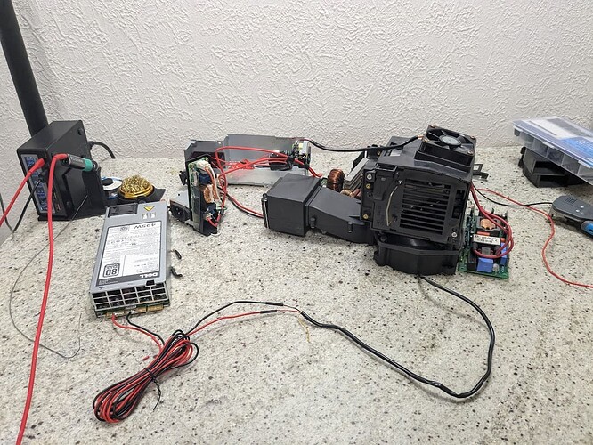
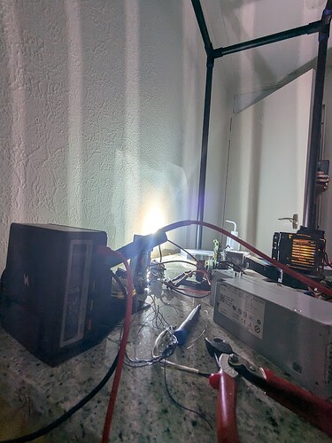
a test setup

photo info 1. all the electronics laid out on a workbench I built so that i could test them while reverse engineering

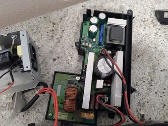
With my experience and knowledge, I set out to find another bulb and ballast that matched my requirements, I found them in my local area, for reasonable cost, and immediately set to work dismantling and identifying the exact boards and parts I’d need. I then bypassed the safeties on the ballast by installing a jumper wire and placing a resistor across the cooling detection pins. Using what I learned from the high voltage safety course, I created a well-insulated wiring harness and built the 340VDC power supply I designed. The final 340VDC power supply isn’t the most efficient but it’s cheap and effective. I wanted to create a mobile unit, so I purchased an inverter to convert 12VDC from a battery to 240VAC which is then rectified to 340VDC. All these conversions create losses, but they’re not significant enough to justify the cost of a more efficient supply.

Then came time to power up the final bulb assembly and start designing the case. Ultimately, it will be a handheld box, with a rp2040 to power everything on/off and a power unit mounted to a harness that I can wear on my back. It will weigh over 22lbs, with most of that weight coming from a 12V lead acid battery (I’d prefer to use a 12V LiPo, but they’re far more expensive).

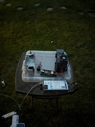
testing setu

first power on

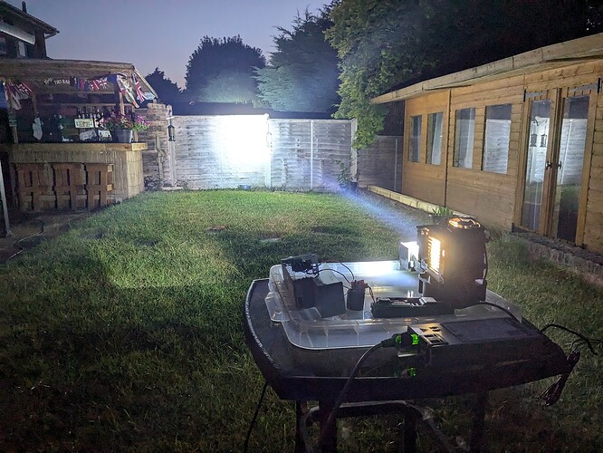
lighting up the clouds

shadow of the trees projected onto the clouds

me looking happy with the light

photo info 1. another test setup which I used to power on the final version
2. the first time light came out of the bulb while not being in my bedroom
3. the beam is so bright it illuminates the cloud cover
4. the shadow of the tree in the beam being projected onto the trees behind
5. me having a lovely time with the searchlight

Using a luxmeter and some tricky math as well as power measurements and lumen per watt values available online, I was able to determine the light’s intensity to be roughly 9.2 million candela, and output 17 thousand lumens. This delivers a range of 6km (3.7 miles), according to the ANSI FL1 spec (scroll to performance standards to see relevant information). For comparison, an average car’s high beams output 30,000 candela and 1500 lumens…
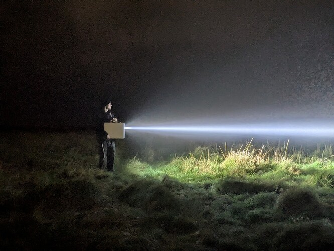
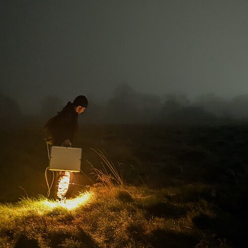
7 Thanks

heres a blog style post i wrote about my progress so far


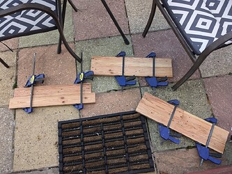
i forgot i had some spare planed pallet wood, total cost is unchanged

going to build a simple box with a polycarbonate lid, might do it with magnets, not sure yet. the back of the box opposite to where the bulb will be will hopefully have a 4 wire slip ring, two wires will be for the 12v cooling and rp2040 and the other two will be 240VAC for the 340VDC psu

I’m going to freehand everything, if we’re allowed to use a router i might cut some pockets in wood for magnets and make a wooden lid. or maybe a dremel would do. i’m not sure yet, but id really appreciate everyone’s opinion on:

  1. wood lid or polycarbonate?
  2. magnets in the lid (no hinge) or magnets in the lid (with hinge)
  3. any other ideas you have for the project