Now that I’m done hopping around the world for a little while, I can finally post my entry into the challenge.
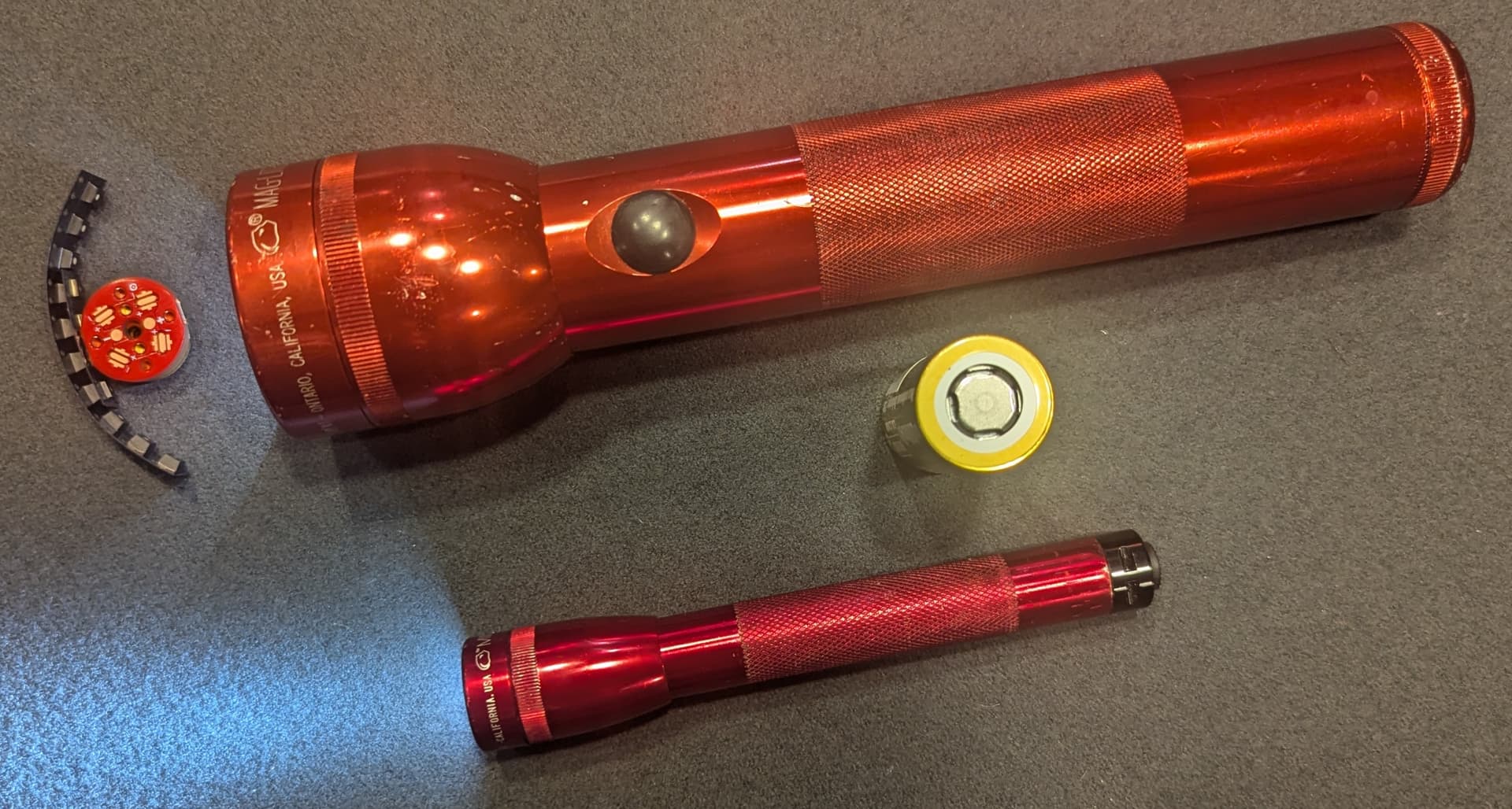
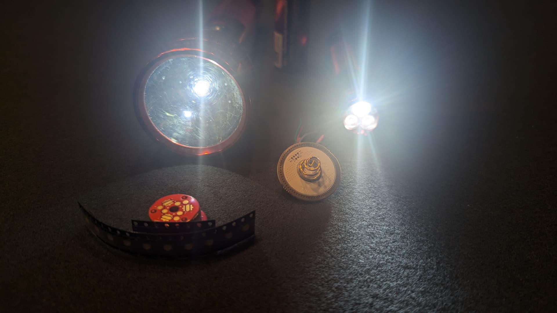
In 1997, my brother bought me a gift set of Maglites. A 2-D cell Maglite and a 2-AA cell Mini Maglite. I’ve already upgraded the 2 AA cell light with a dragon driver mini, 2x FFL351A’s and 1x SFT25R, and powered by a 14500.
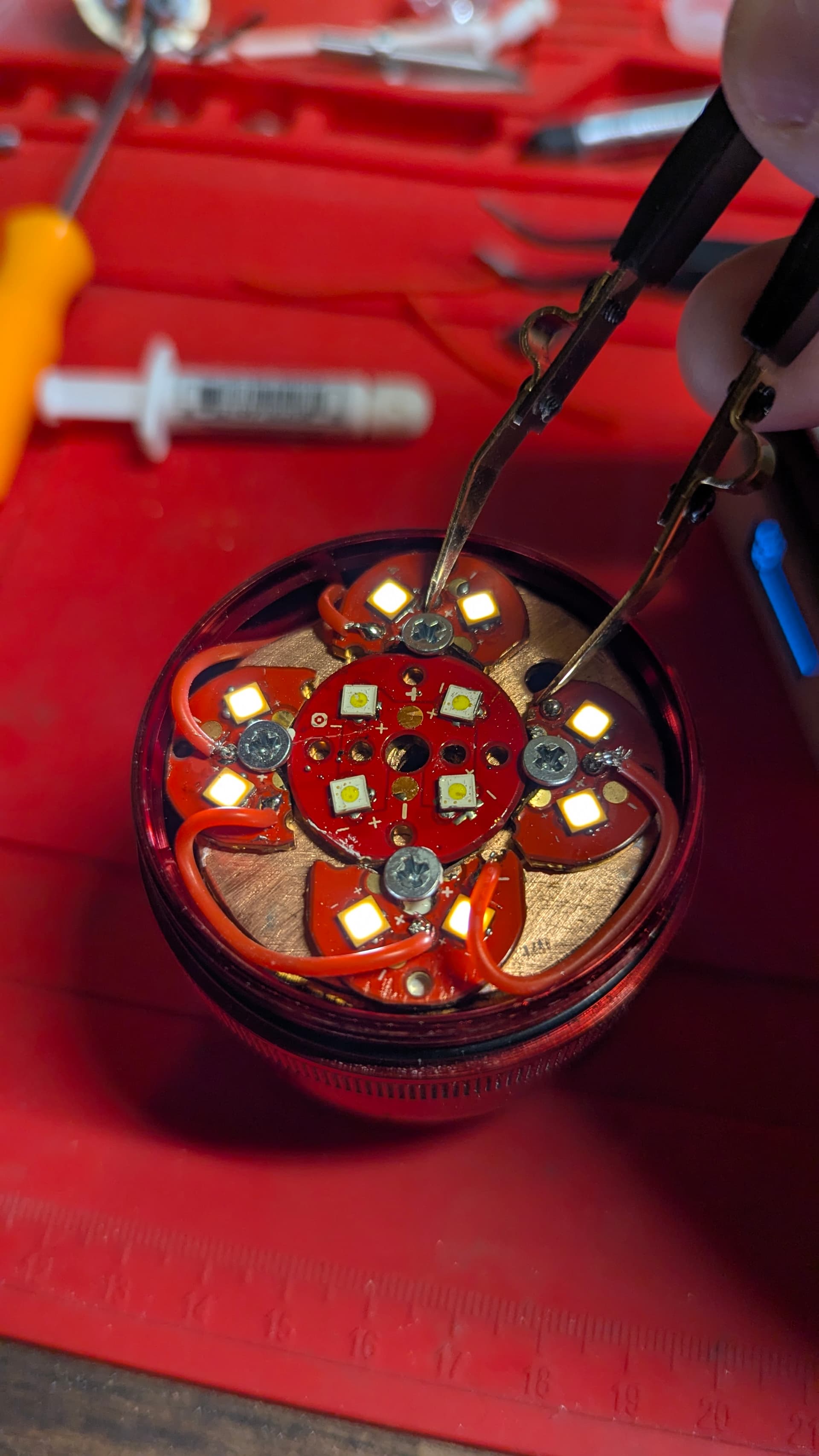
A few of the components going in this light are shown. But, not all. I’m still working out how I’ll complete some of the components. And, I’ve got ideas. But, if it all works out, it’ll be the baddest Maglite around.
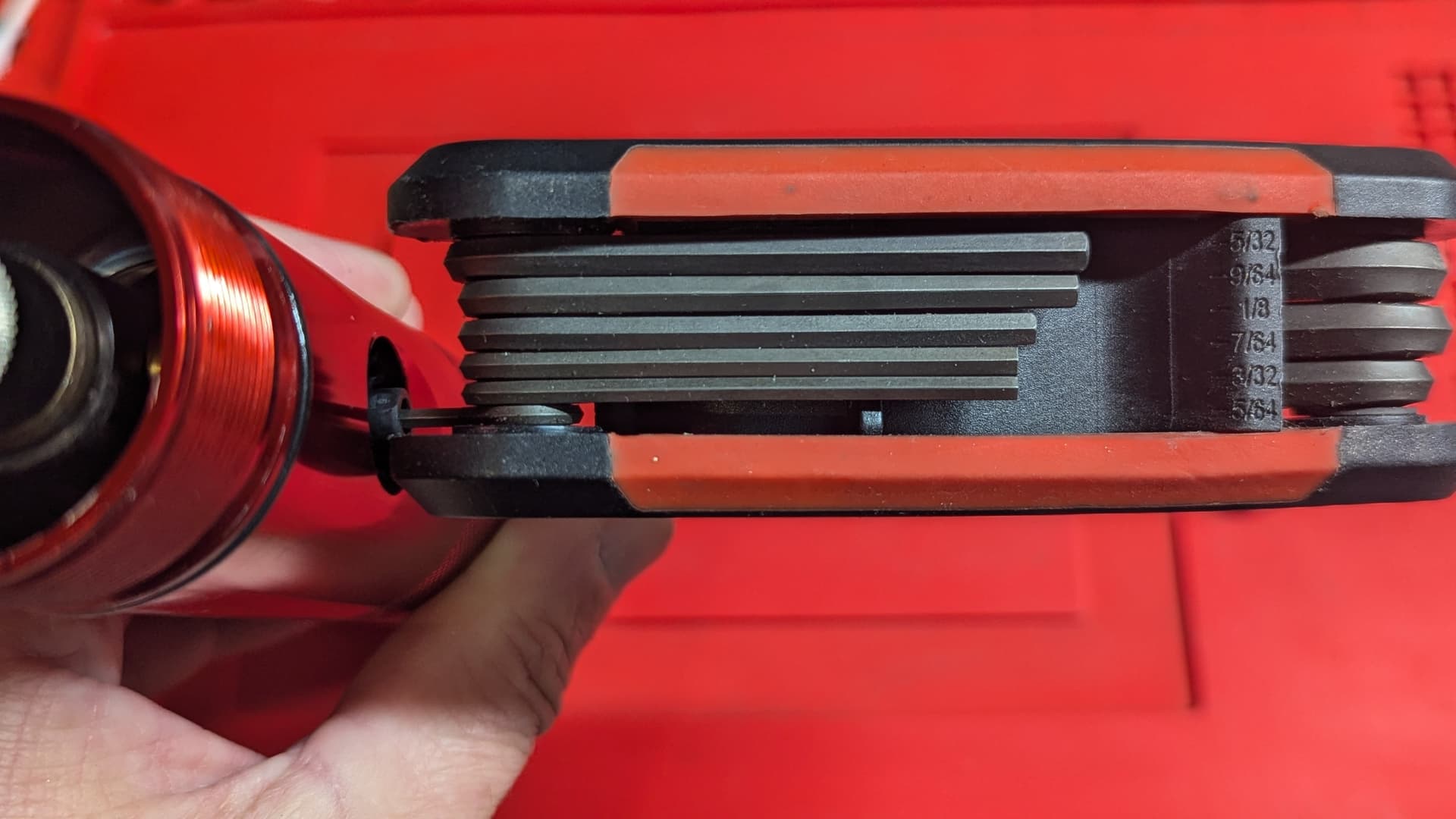
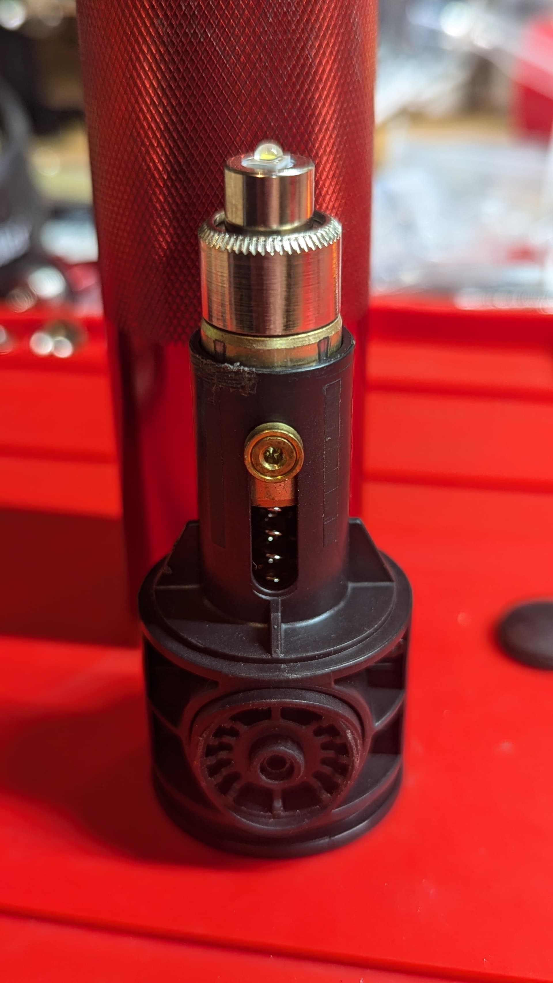
Disassembled the Maglite last night. It’s crazy easy to take them apart, once you know the trick. Take out batteries, unscrew head, pop off button cover, there’s a tiny hole in the center of the button. Put a 5/64" hex wrench in and push it all the way through. You may have to twist it to get it to pop into the socket. Then unscrew. The whole assembly will drop down and out. That’s it!!!
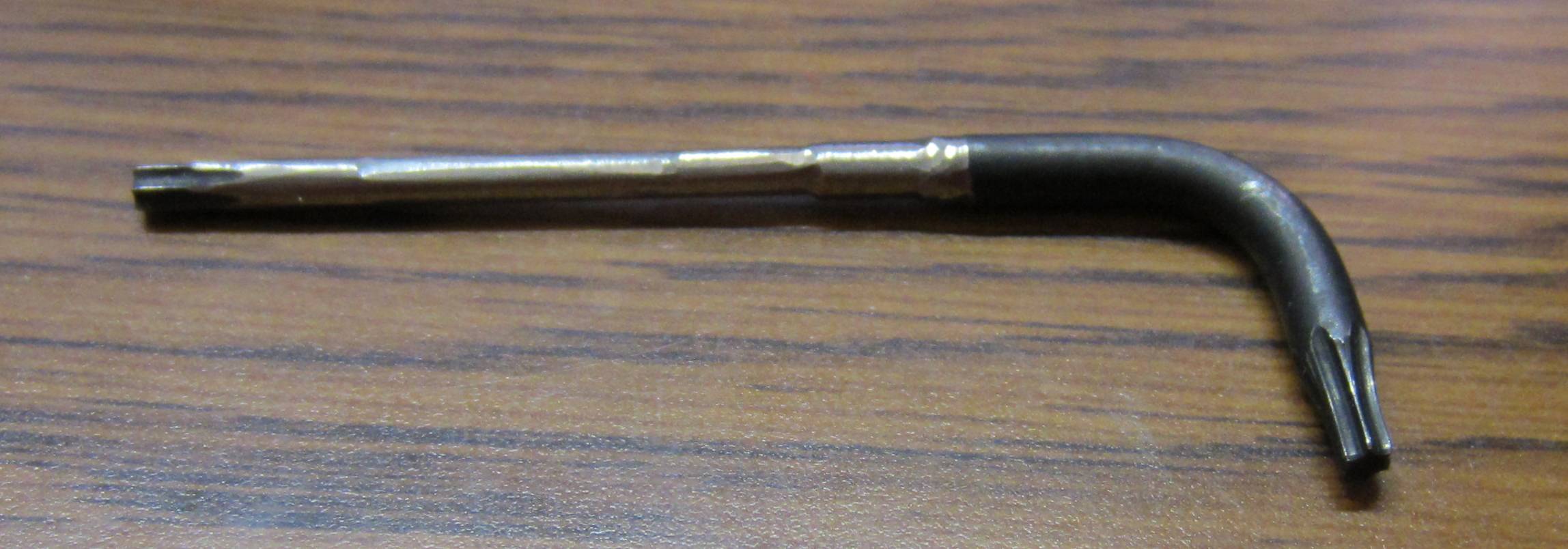
The trouble is that the hole through the switch is not large enough for any off-the-shelf T8 torx tool shank to fit through, so you have to grind down the shank of a T8 tool to fit it in there. The shank needs to be ground down to the same diameter as the T8 spline, which is .090". A .091" gage pin does not go through the switch hole.
Had never seen that. But that’s kinda crazy. Also to think that something like a thinner shank would stop a modder from doing their thing! Kinda weak, really.
It is definitely an obstacle, and unless you go digging through the flashlight forums, you wouldn’t know what tool to use. Even the post about switch removal on the Maglite history blog doesn’t tell you what to do, it just says you need a “propriatary torx tool” which you can only acquire from Maglite with the purchase of a replacement switch kit. That replacement switch kit costs more than a new Maglite does, I’m sure.
I suppose you could follow this guy’s instructable and bash the switch housing out the front without unscrewing the screw first…
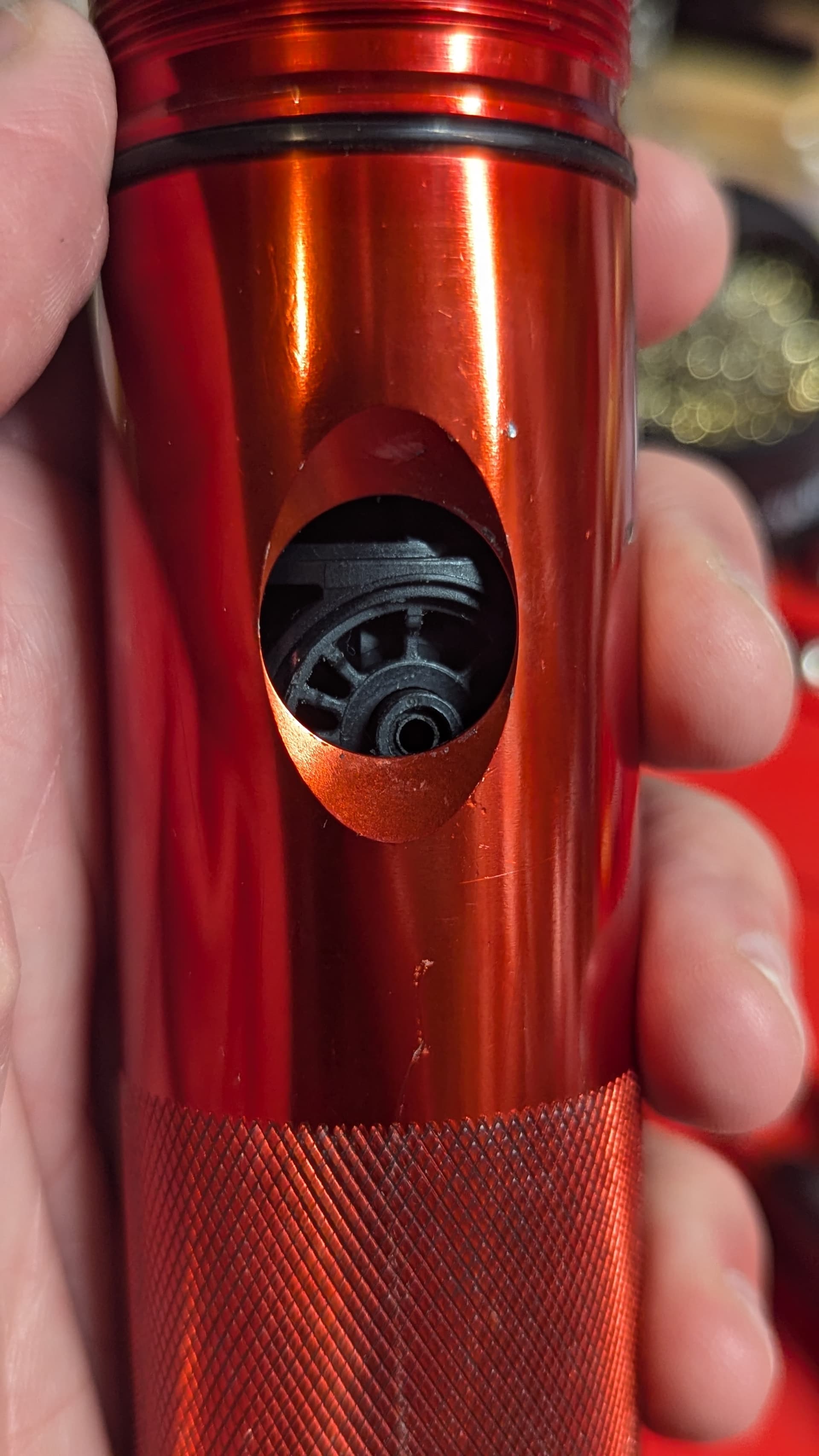
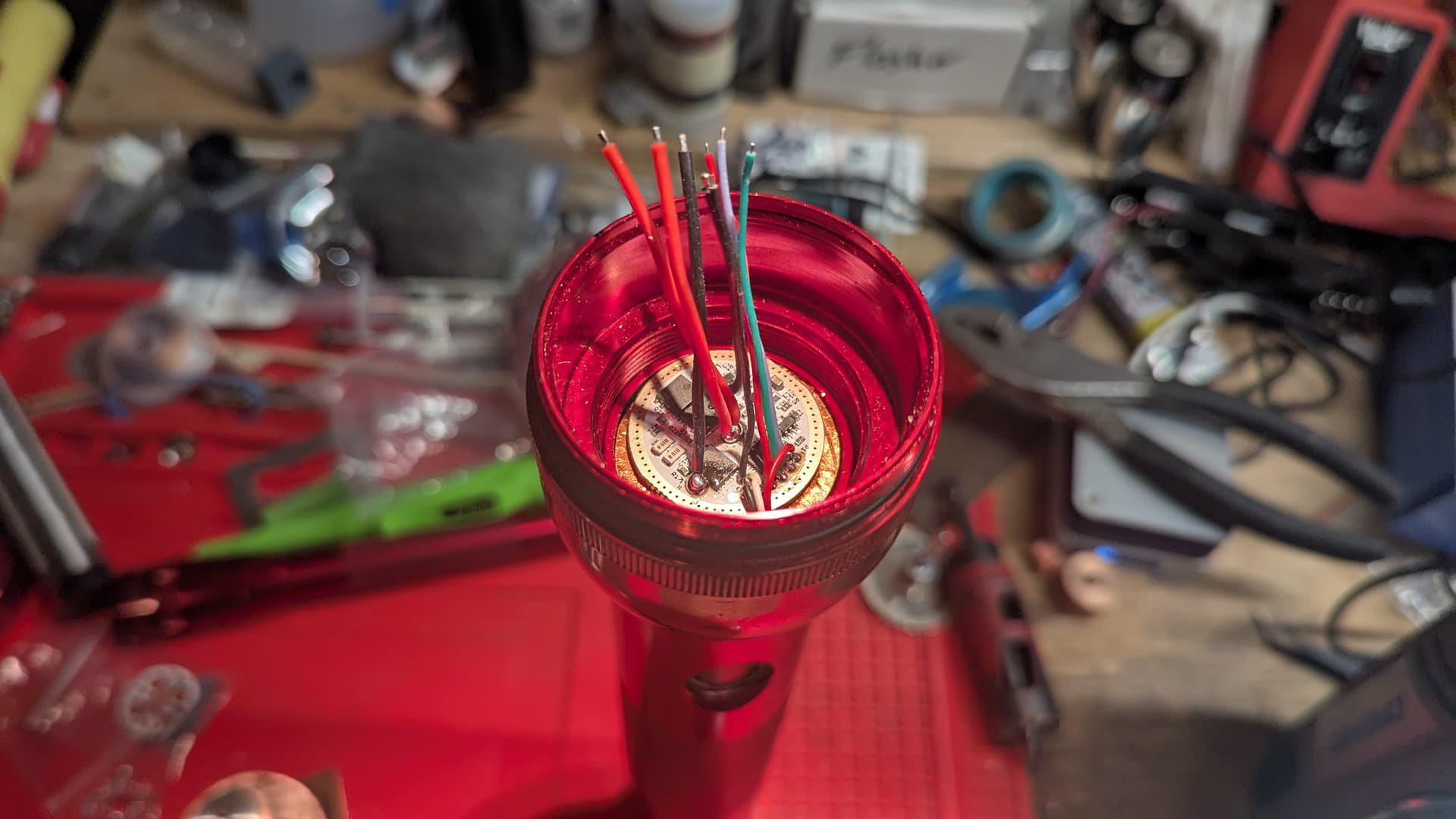
Made a little progress on the build. Now I’m waiting on parts that should hopefully be here on Monday. I decided the best way to build this is going to be from the lens down. Right now I’m working on creating a pill.
Made some great progress the last couple of days. Got the battery tube all situated. 1" PVC first perfectly in a 34mm tube. And a 26650 is only slightly larger than 1" (1 inch = 25.4mm) so I sanded the crap out of the inside to make it fit. Then I cut another length to fill the gap between the battery and the pill for the driver (more to come on that spacer as I’m not done with it yet).
The pill is nearly ready. Though I’m still trying to work out the best method for it. If I put it in the way I’m currently planning, I won’t have access to the flashing pads. Mostly due to switch placement. I could, however, try creating a larger pill that would include the switch. But it would still be a beyotch to get to the pads.
Or, I could flip the pill upside down and put the driver at the bottom. But, then I lose the thermal protection ability. I mean, it’d still be there. Just far away from the emitters and basically non-existent. (This is probably what I’ll end up doing.
Edit: I’m still at the mercy of the switch! Dernit!!! Doed anybody make a tiny 3 wire clip I could use here? Or 3 tiny 1 wire clips? LOL!
Anybody’s thoughts on this are appreciated!!!
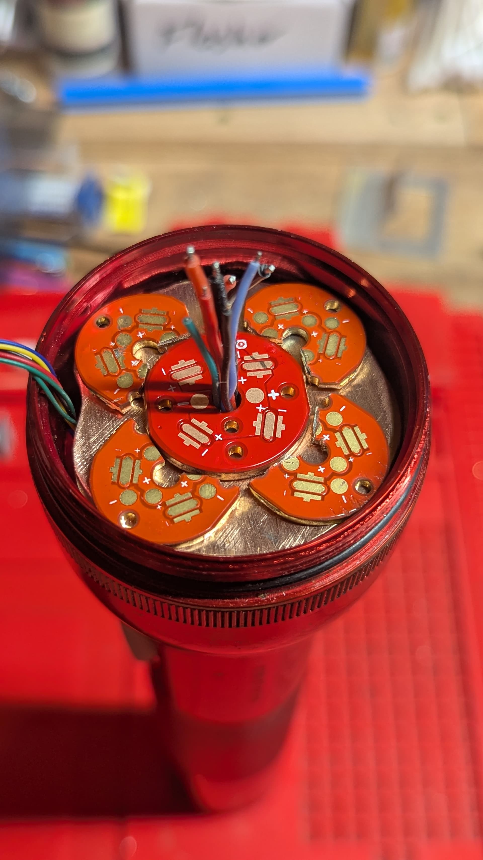
Anyway, here’s the pill and then in the tube with the driver placed!
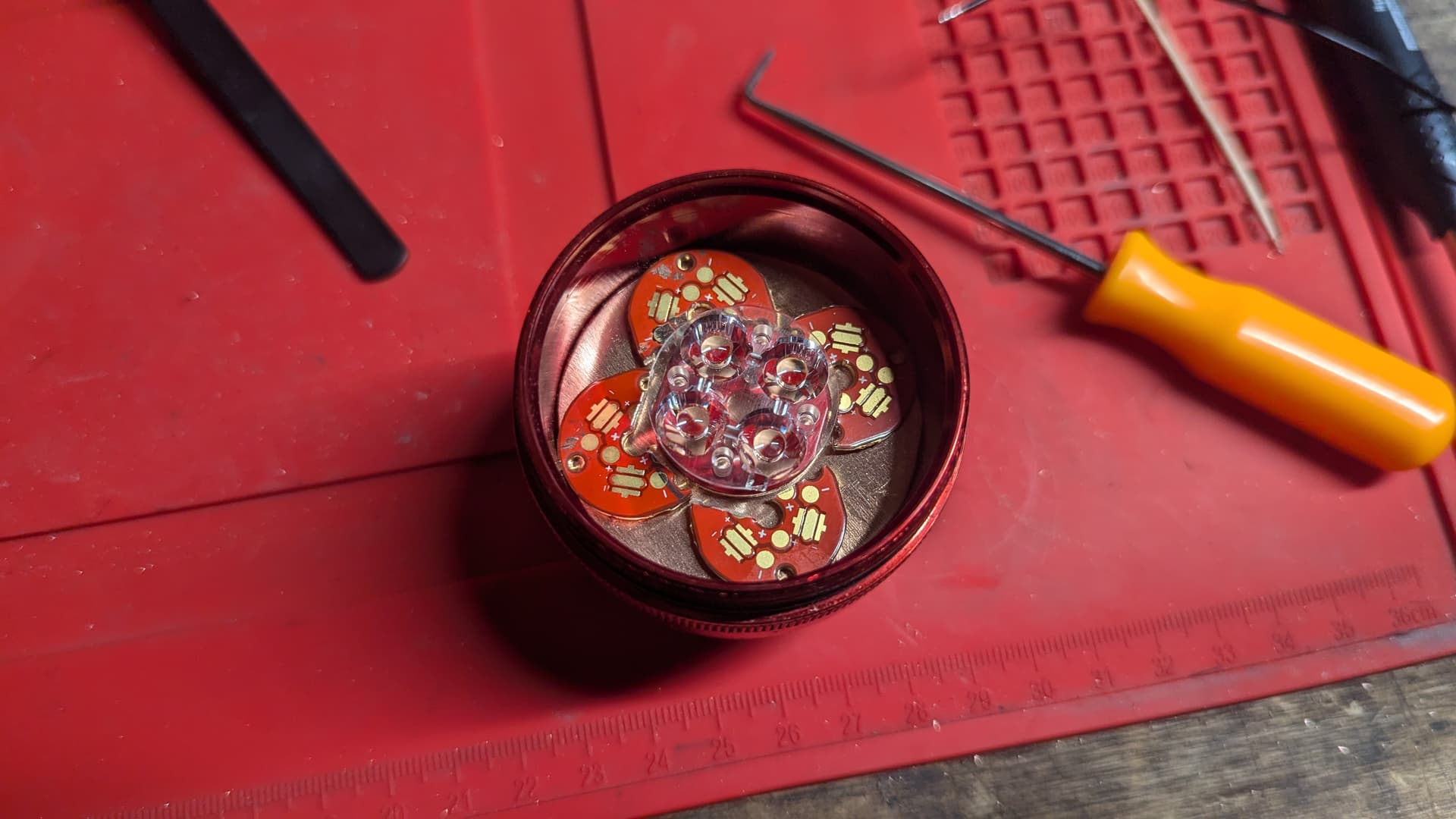
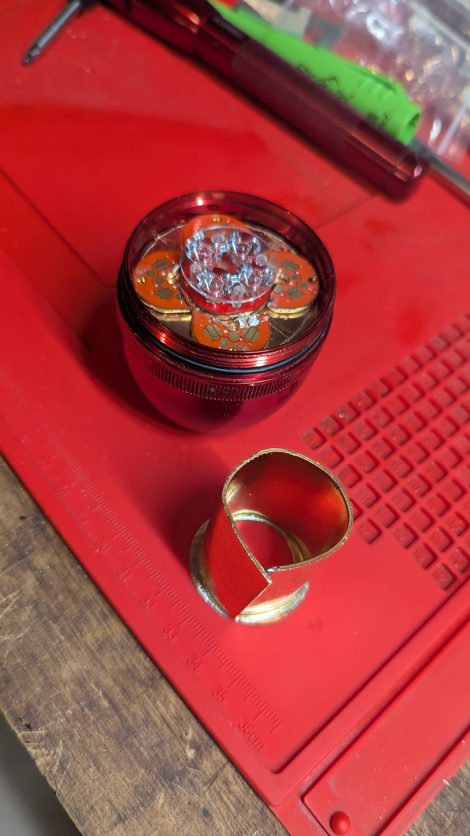
Looking good so far! Are you planning to use a quad optic with four leds or four triple optics with twelve leds? Or will you have two separate channels?