Help - advice for Convoy red S2+ driver ground

(I edited the title of this adding “driver ground” to be more specific)

So I got this red convoy s2+ with the metal switch (7135*8 2.8A) back when they had them for $12.99 on the Gearbest Special Deals.

Mine is not the fake version judging by the comparison photos in this thread: Red S2+ flashlight ,for girls,for your lover (post #651)

It was my first Convoy and I wasn’t thrilled. It didn’t seem all that bright and the modes were sometimes a little “jumpy”. Unimpressed I tossed it in a drawer, figured I’d try it again later when I had time, besides I had just got the BLF A6 to play with.

-

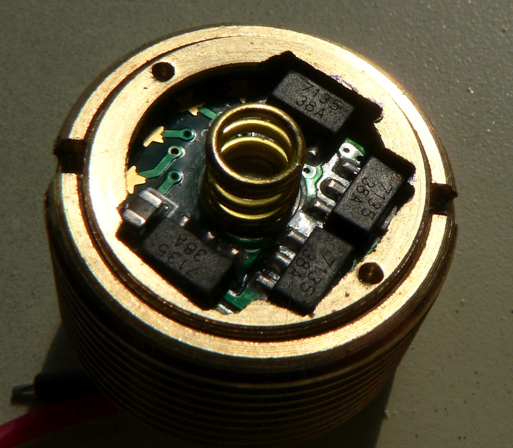
So now I had a closer look inside and the first thing I noticed was what appears to me as crappy soldering between the driver and pill. And the soldering was partially over top of the two notches used for unscrewing the pill. I thought why would they solder partially over the notches? Looking closer I noticed the driver was actually loose, and may have moved from its original position because the soldering didn’t hold (or wasn’t solid from the get go)

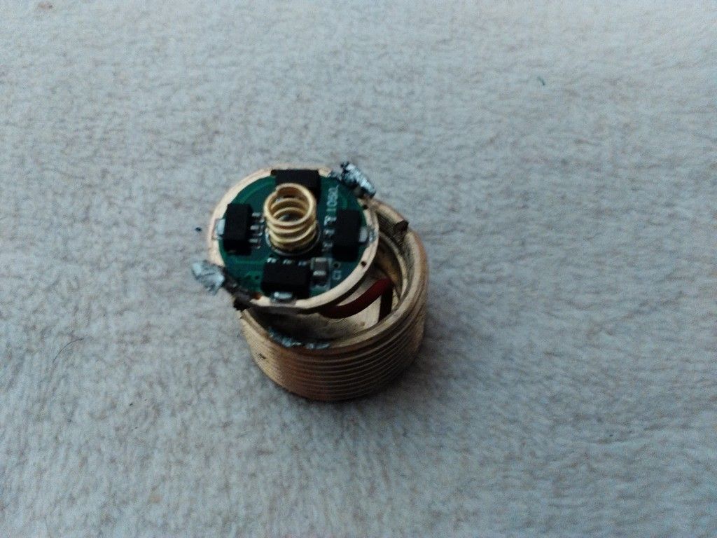
Since the soldering is the ground between the driver and the pill, (completing the circuit from battery negative through the switch and body) I have to assume the broken solder joints are the root of the problem.

-

So my question is what is the best way to ground these? (I know this is pretty basic stuff but I’ve only recently began flashlight mods/builds/repairs)

I did see this photo on one of the Convoy (Simon’s) flashlight descriptions (S6):

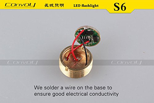
Followed by a photo of a board in a pill with no solder and this wrote in:

“Don’t need adding tin on the edge, more beautiful!” :slight_smile:

So I thought why isn’t my Convoy “more beautiful”? :frowning:

-

Is the ground jumper wire best? Would it create higher resistance? (I ordered some 22 AWG premium oxygen-free copper/silicone wire)
Or is there another preferred method?

I also thought how it might be kind of hard to get that center area of the pill hot enough for the solder to stick to it, after all it is a big heat sink, so maybe that’s why they solder to the thin edges instead?

-

Another concern I have is with the “thermal compound” under the MCPCB. It’s a grey liquidy substance whereas I’m used to seeing a (usually white) thicker paste.

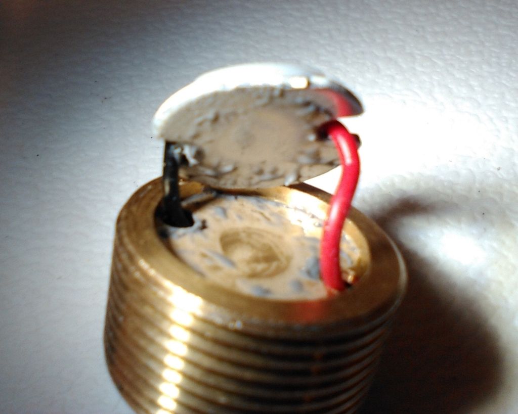
I’m sure it needs something better because the light should get fairly hot, just wondered what the grey liquid was? I’m getting some Arctic Silver 5 Premium Thermal Compound so I’ll give it a dab of that instead.

It can be difficult to solder to a big chunk of brass/copper, especially if it's semi-assembled, & you don't want to cook the components attached to it.

An average iron with a thin tip will get the heat sucked right out of it.

Flux, & a decent iron with a reasonable size tip will get the job done.

If you are assembling from scratch, it's a good idea to think ahead, & pre-tin any surfaces. You can use a blow-torch to assist in getting some heat into the object prior to hitting it with the iron.

What FmC said.

alternative method would be to make things into a pressure fit situation.
they are not as good as direct solder as they might pop off when you drop it empty without a battery but current wise it’s close to similar.

I made the diameter of the driver wider with some extra wire and solder them externally just big enough for a snug fit.
You got to make sure the brass part is clean and force the driver in with clamps or something.

easy fix. it’s already tinned. just set it back in there and hit it with a hot iron and more solder. good you caught it at your bench and not when you needed the light to work.

I’d suggest soldering the star and taking everything apart. Then apply some soldering paste and use a blow torch to heat up the pill. Then when you put everything back together it should be easier to solder the ground to the pill.

While you are at it, perhaps you make want to consider using a copper MCPCB. Then you can also solder that to the pill instead of using thermal grease.

Best way is to use the little threaded retaining ring for the driver that should have been installed.
You don’t need to solder the driver into the pill, you just clamp it down.
It can press on the 7135 chips without causing a problem.
If you don’t like the fit, file notches — the retainer is wide on top but undercut so it’s thin around the edge that contacts the driver ground ring.

discussion at (set to see 300 responses per page, then this link will work)

Dunno if they didn’t give you the retaining ring, or soldered over its threads. Sounds like a mess.

Thanks everyone for all the suggestions so far. Keep em coming!

So it looks like there are only 3 options:

1. Solder on bottom edges (like it was)
2. Jumper wire (like convoy’s S6 photo)
3. Press fit with conductive shim material

The jumper wire to me seems like a good idea, then if I ever wanted to swap out the driver I think it would make it easier. However I’m wondering if its ok to have the driver just setting in there unsecured like that?

-

Yes I was thinking to just re do it like it was, there is some light tinning on one edge but none on the other opposite side, does it really need the double grounding like it had if there is one good one? (but I guess that would hold it in better)

-

I have the large propane Bernz-O-Matic style torch like you’d use for plumbing, I could hold the pill in a vise and heat it to “pre tin” the area where I will ground. I guess at that point if I’m going with the wire I could just solder the wire right then after tinning with the torch while it’s still hot.

If I’m using the torch to tin/solder a jumper wire where it shows in the Convoy photo, is there any worry of distorting the flat surface on the other side where the MCPCB sits? I think the pill is brass not copper, at least it looks like brass to me.

-

I have a couple of the old large Weller soldering “guns”. Can’t remember how may watts they are, maybe 60? They have several tips in the kit, I know some of those tips are quite large. I think they would get pretty hot compared to my Weller WP25 iron (25watt) the iron has a small pointy tip. Maybe using one of those guns would work on the pill instead of the blow torch?

-

As FmC suggested you’re saying to use a blow torch with some solder paste to apply a “tinning” to the surfaces before reassembling?

I also have a few mini torches, one is Butane and one is the (old) Radio Shack kind with the dual tanks, I’m sure that one would get hotter but I’m not sure if you can still buy those mini gas cylinders. I guess with the pill removed the plumbing torch would be best.

Interesting. Yes I see the inside threads for the ring, and they look ok, no solder on them, but I didn’t get a ring with it. I see the ring comes with the s2+ host and also the s6 host so now I’m wondering why they wouldn’t have just used the ring.

I’m also wondering why they show the photo with the ground wire soldered in the pill in the description of the s6 flashlight on Convoy’s site, why wouldn’t they just use the ring?

EDIT: It doesn’t look like that ring is made to fit with these drivers, but your saying even without doing the cutouts it will still contact the ground ring on the board?

Yes either one will work. You can also add the wire if you would like, but don’t think it’s necessary. I would not suggest using the light with the driver loose like that. This is the soldering paste I use.

I don’t know which driver you have there, but each of the Convoy lights I’ve bought — S2 and S2+ — came with a driver retaining ring that worked.
See the picture linked for how to file out notches (and pre-reverse-twist the wires) if you need to fit it over a tall stack of chips and still screw it down tight.

I just in today’s mail got another Convoy S2+, blue, that I’d ordered quite a while ago — same $12.99 Gearbest Special.

And this one came with the driver soldered in, no retaining ring. Just like you describe, solder right next to the notches for unscrewing the pill.

Now I’m more than a bit puzzled.

An earlier blue S2+ Convoy that I bought from them a few weeks earlier, on the same deal, came (much sooner) with the retaining ring in place.

So did the two red S2+ Convoys I got from MtnElectronics for $12.25 a few months back.

So — how come this one blue S2+ was so long delayed, and came differently put together?

Subcontractors?

answering your question earlier:

“even without doing the cutouts it will still contact the ground ring on the board?”

Well the retaining ring has an “L” cross section so the thinner outside part goes down past the components and probably reaches the ground ring on the driver.

Either that, or if the components it presses on are too thick, then pressing on those will press the ground ring on the emitter side of the driver down firmly where it contacts the ledge the driver sits on.

Haven’t had any trouble either way.

So I’m very curious — has anyone else gotten a GB special Convoy done this way?
Mine are both T64C*8 — the one that came quickly done as normal with driver retaining ring; the one that took forever to arrive with driver and pill stuck together with solder instead.

Matters to me since I like being able to swap drivers easily.

i had a feeling someone is selling scrap metal by stealing some retainer rings yo

the qlite driver is difficult to use with the retaining ring since the chips are sitting so close to the edge. I use the retaining ring in c8’s but for the s2 you need to use the methods above —-if youve stacked chips on a qlite, imo forget about using the ring without filing notches. i kinda like the groung wire idea——my c8 was getting some faint flicker until the ring was tightened to the point of stripping the ssnapring holes (the aluminum type)……so i think the ground wire might be good—-but still would require torching beforehand to pre-solder it

i had the same type of question a little while ago and got some great replies with links to a really good pill/braid/solder write-up:

Thanks for the answer, I never considered the ground ring contacting on the opposite side.

Maybe I should ask Simon why we’re seeing these soldered ones? After all its his product (supposedly) that they’re selling, isn’t it?

Sure, anyone in touch with Simon please do ask.

I realize it’s possible this is considered OK from his end — most customers wouldn’t notice or care, if the soldering is done right
(unlike the original post here where it cracked loose, of course, that was definitely bad).

Looking hard at the one I got that’s soldered in, it actually looks like little bits of copper or brass are buried in the solder making an arch between driver ring and pill.

Could be Simon approved it if retaining rings weren’t available. If so, well, tolerable. I would like to know.

If not, then it’s a WTF — either he didn’t catch some bad production going through, or some intermediary after they leave his control is changing the drivers for some reason?

Hard to imagine, but over the years I”ve seen cheeseparing, corner-cutting, and penny-pinching have driven some very odd substitutions.

As far as I know all Convoy S series lights have the drivers soldered in place when the driver is double sided. i.e. Nanjg 105C/D drivers.

I have an S2 from FastTech, S6 from MTN, red S2+ from Gearbest, all with soldered 105D drivers.
I also have some S2+‘s directly from Convoy’s Aliex store. These have the default ’AK47’ 3*7135 drivers, not soldered. Same for an S2 UV from Banggood.

This is a good reason to buy hosts only or to stay with the 3*/4* 7135 drivers. It is easy enough to stack 7135s on the single sided drivers, if really required. Another reason is to avoid the rigid 105C/D spring. Already dented a cell when a light dropped 2 feet onto a hardwood floor.

All my soldered drivers have been replaced with single sided Nanjg or FET+1 drivers. These rings fit well:

https://www.fasttech.com/products/1583600