Its getting darker in the evenings now and thats a great opportunity to build a high powered flashlight. I have made the first move regarding my project by creating a build thread.
My idea is still to be confirmed. I have a rough idea in my head but im not sure how exactly to carry it out. All I want to reveal for now is that im planning to build a long throw flashlight.
I have a couple of components lying around which I can use and also some materials. I also ordered some stuff for this project which should come soon. Im waiting on the optic especially so I can measure up and design something that will work out. I will keep you updated as soon as I have came up with a definitive idea and once the actual build process starts.
First update
Sorry about the wait but I feel like now is a great time to inform you about the build as I have picked the idea and the flashlight components required for this build have arrived. I will be working with a convoy L7 flashlight host as my starting point but it will need some heavy modification to achieve what goals I have set out with a very specific use case in mind:
1: I want to include multiple high powered LED’s (3xSFT40) for their brightness and throw
2: The flashlight needs a very bright but also focused, intense and throwy searchlight-style beam. This light will be used for locating and checking on livestock (sheep) at night. I want a couple thousand lumens and I’m aiming for 1km or 250,000cd of throw.
3: It should be easy to use (the L7’s dual switch seems ideal)
4: Sustained operation is a must. The original SBT90.2 or XHP70.2 are known for overheating and activating the thermal stepdown after a short time of operation. I want to include additional heatsinking and by choosing the SFT 40, I should achieve almost twice the efficiency of the SBT90.2.
5: (personal preference) I don’t want a soda can form factor as its bulky and difficult for me to hold. I would prefer a traditional flashlight style form factor like the L7’s host. It would be much easier to stow in a vehicle such as in the door side pockets and if the flashlight does overheat I can move my hands further down the handle to avoid burns.
6: Budget price I’m not willing to spend hundreds on a high powered flashlight with multiple LED’s like the BLFGT4 or the Wuben A1.
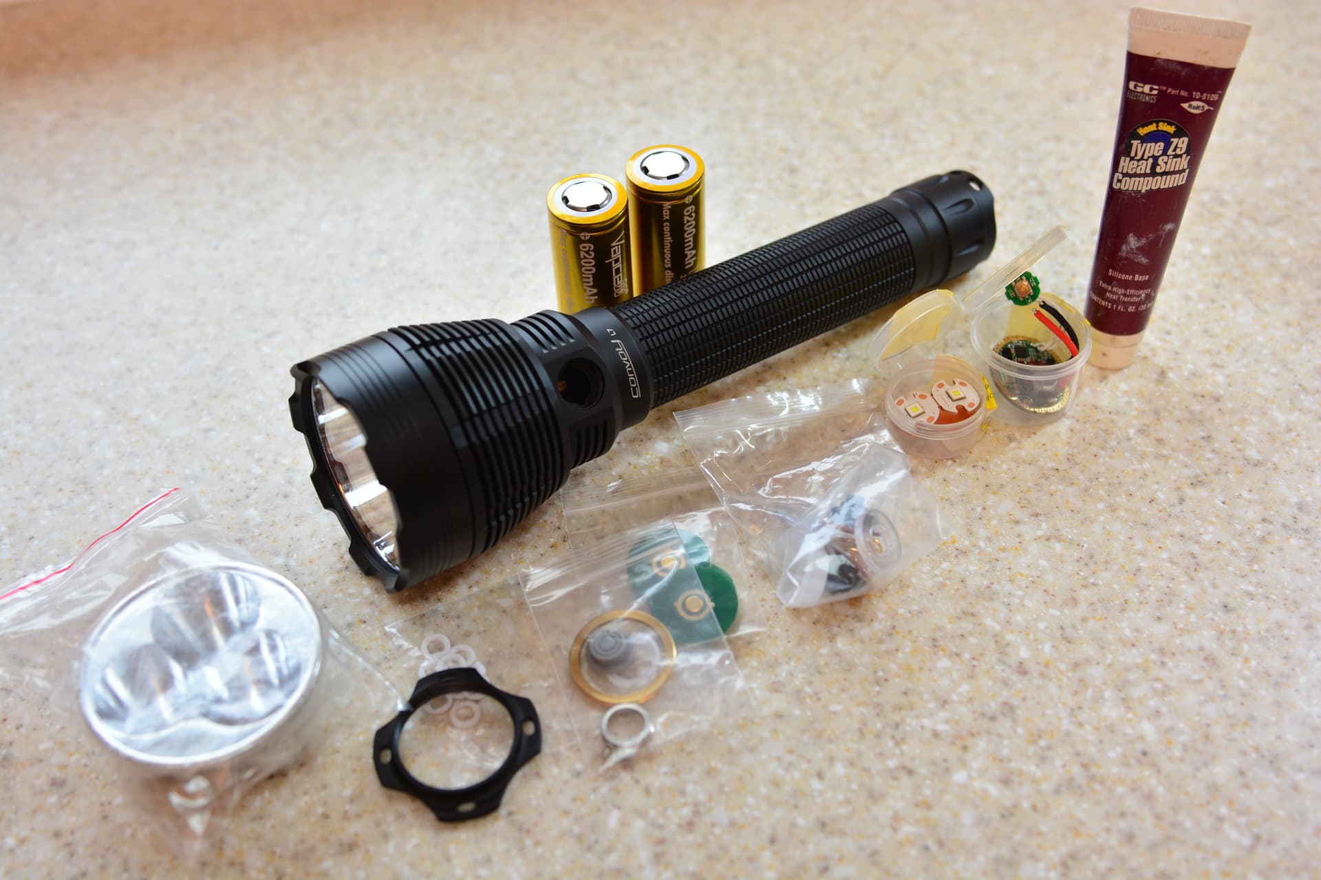
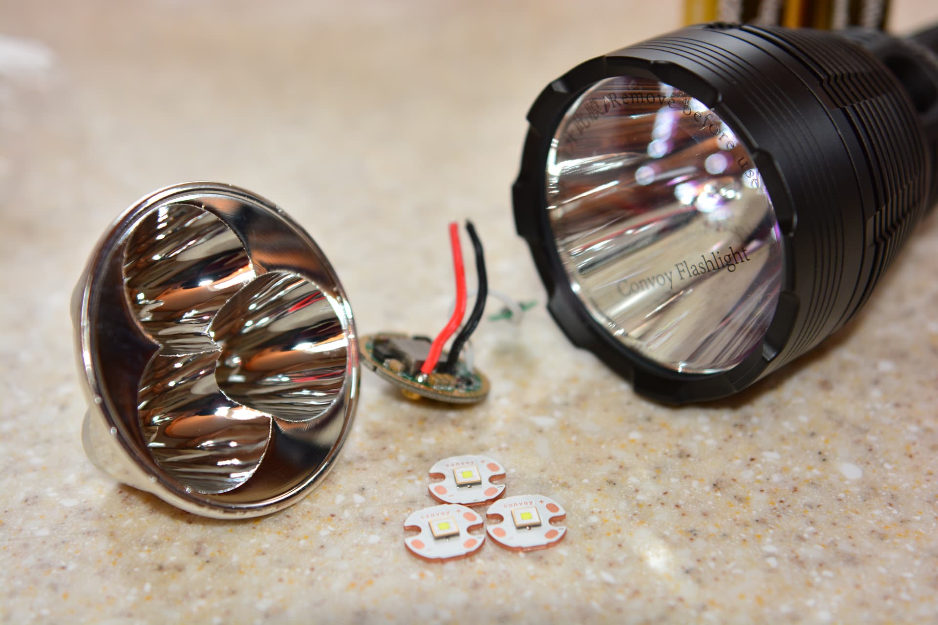
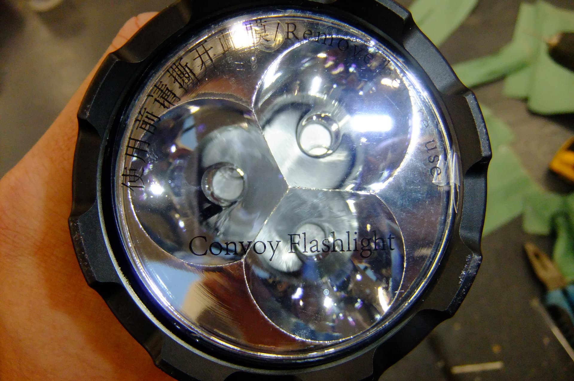
Here are some photographs taken before beginning the build. So far these are all components which either arrived or I already had. You can see my starting point for the build is the convoy L7’s host. My plan is to install 3 SFT40 LED’s and focus them into an intense beam using the biggest triple reflector I could find online. This was kaidomain’s 65.5 x 32mm optic which should be a good match for my host. The driver is convoy’s 30mm sbt90.2 driver with 20.5 amps which should give me about 65watts of output power. I am limited by choice of driver due to the host’s dual switch setup. This should be adequate as each led should be getting about 7A of current (max is 8A). I have also got two vapcell k62 26650 batteries as these have a decent draw rate and one of the biggest capacities I could find. This should extend the total runtime. Its also worth noting this will be my first experience with 26650 flashlights. I also purchased a convoy lighted switch kit. This was a mistake as it won’t work due to the 6v voltage and bigger switch diameter.
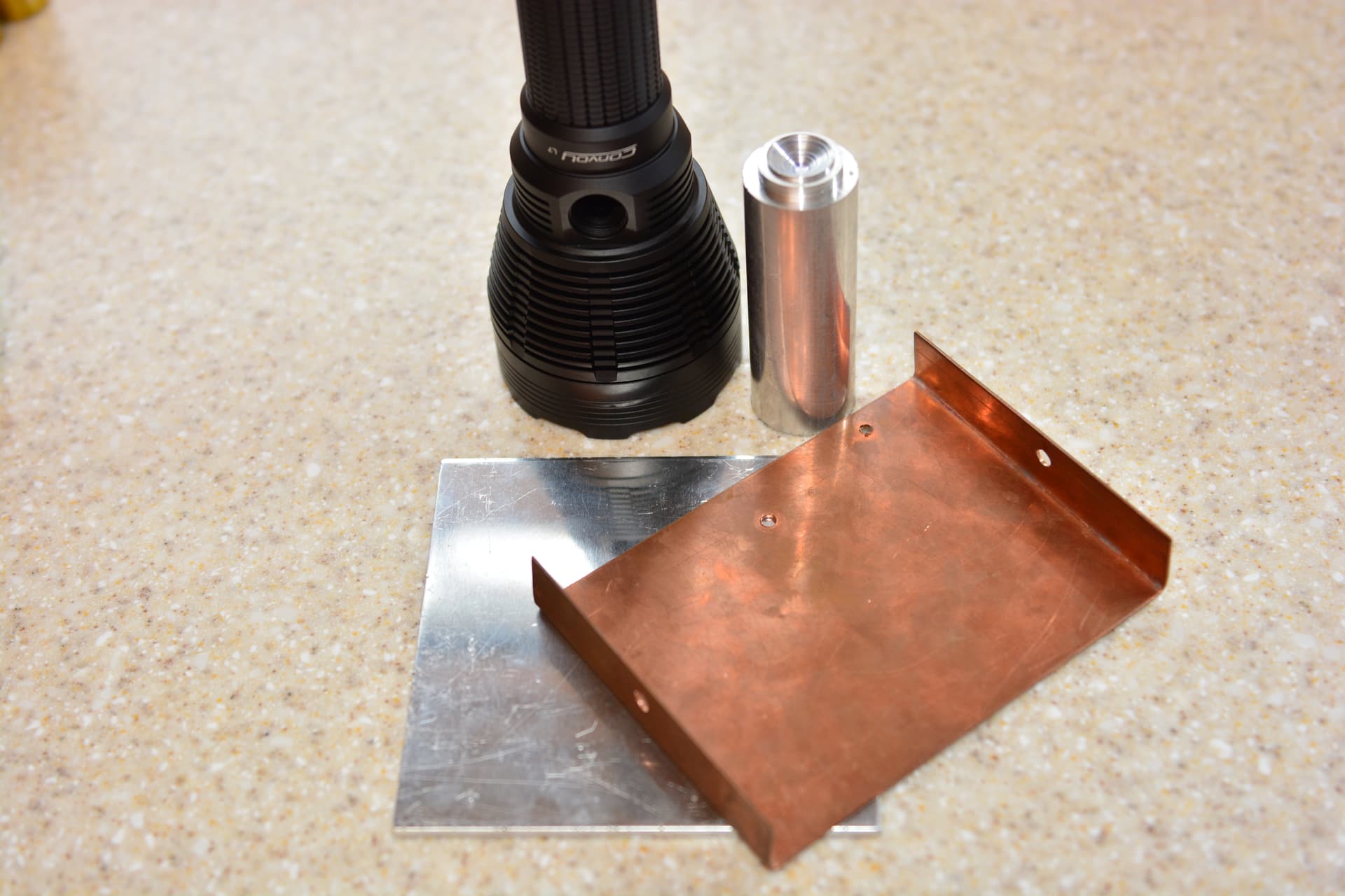
I also have some raw materials which I’m planning to use to make up the flashlight’s heatsink or triple spacer. The flashlight head will need to be modified in order to accept the smaller reflector and make good thermal contact. I will design a component to fill in this gap. The scrap copper plate I’m planning to solder the 16mm MCPCB’s with the SFT40 LED’s to create my own version of a triple MCPCB. The spacer component will be made out of aluminium metal plate, and round metal bar (this was a leftover from last year’s build). I will need to buy larger diameter bar as this is only 30mm in diameter. (I need 56mm).
2nd Update
I actually began the build process, and instantly hit a problem. I needed to use a lathe to machine the spacer component. The only person I know is my friend that allowed me to use it last year, but the problem is that its a smaller, entry level lathe and the chuck can only open to accept max diameter 40mm bar.
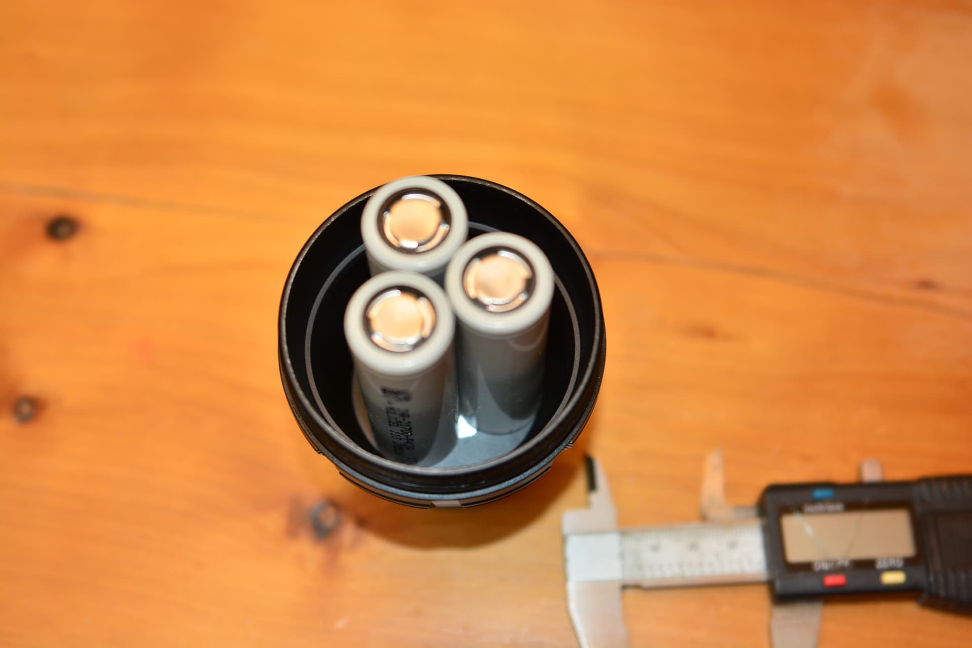
I then designed an alternative made up of three separate pieces of bar which can be machined on this lathe. Plus I wont have to go out and buy additional materials. I was able to figure out that by sitting 3 21700 batteries into the head that I should make the bars 20mm in diameter to allow a gap.
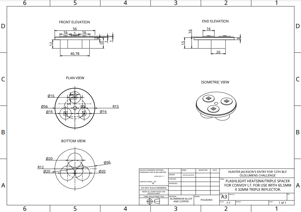
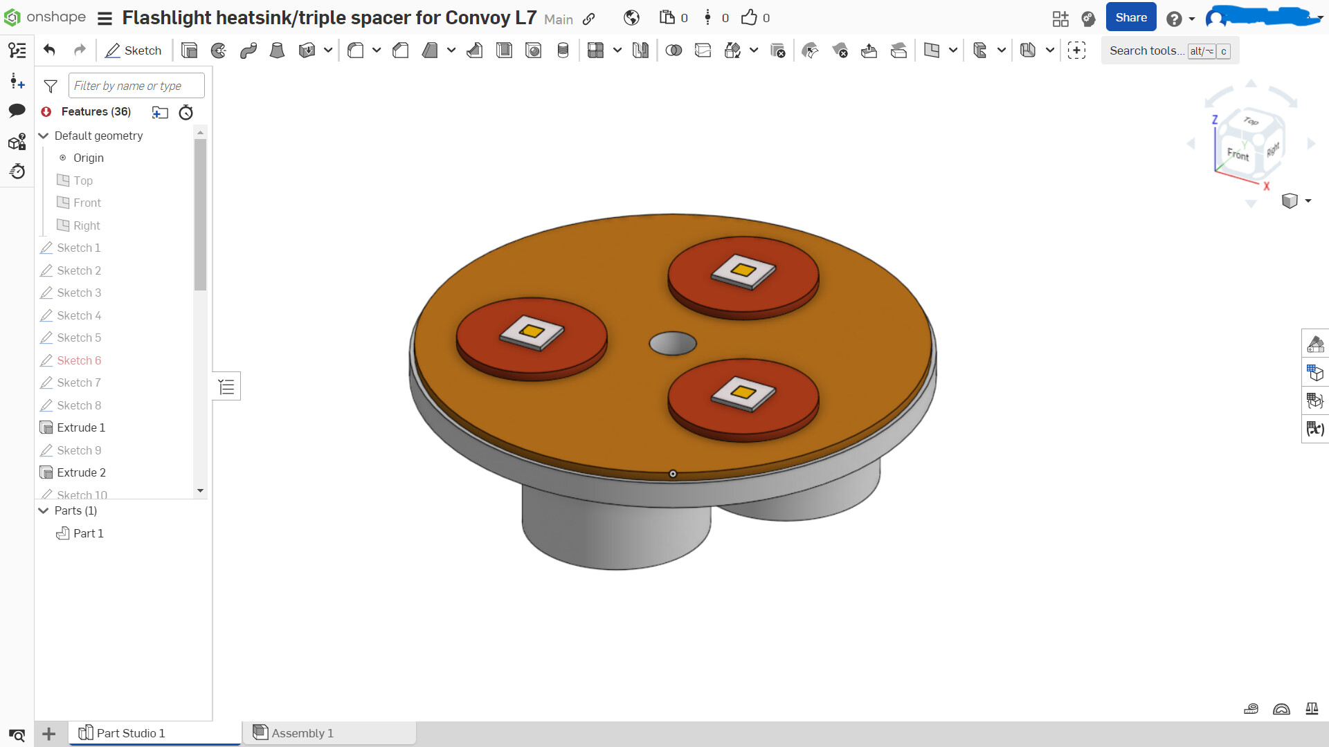
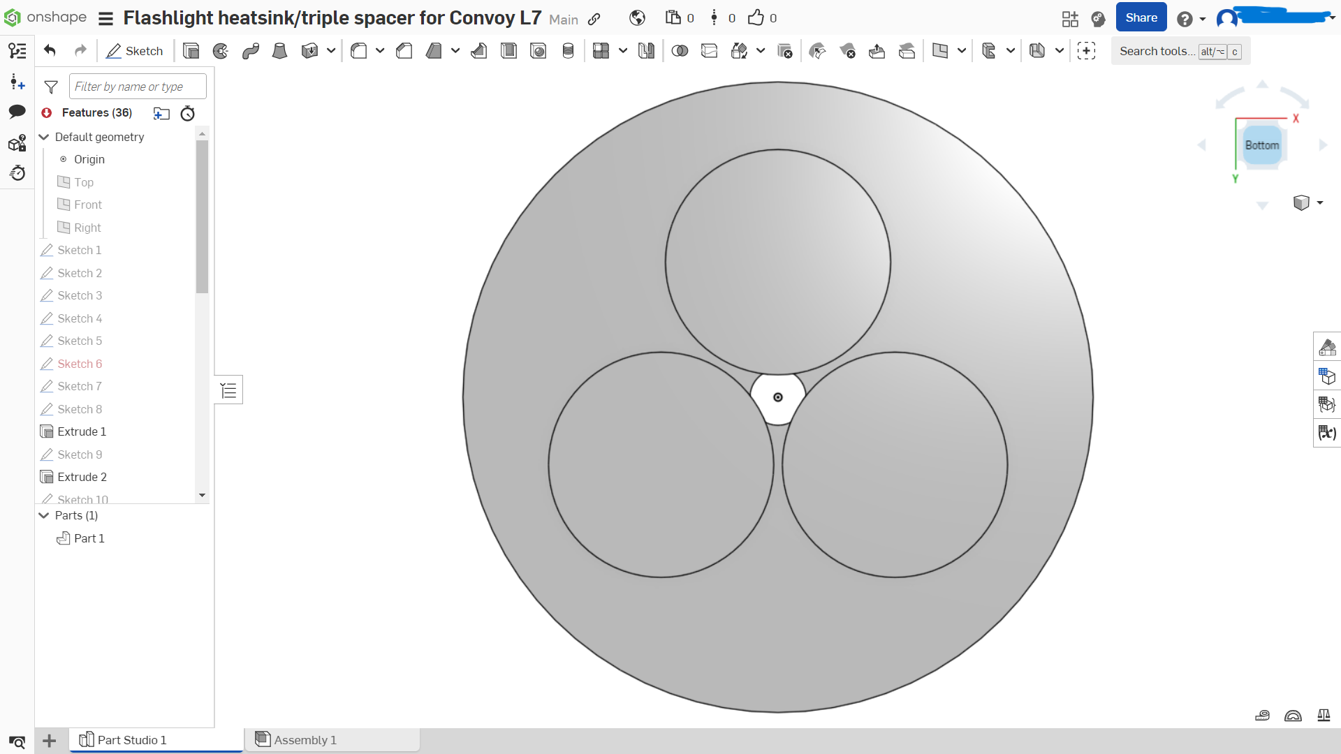
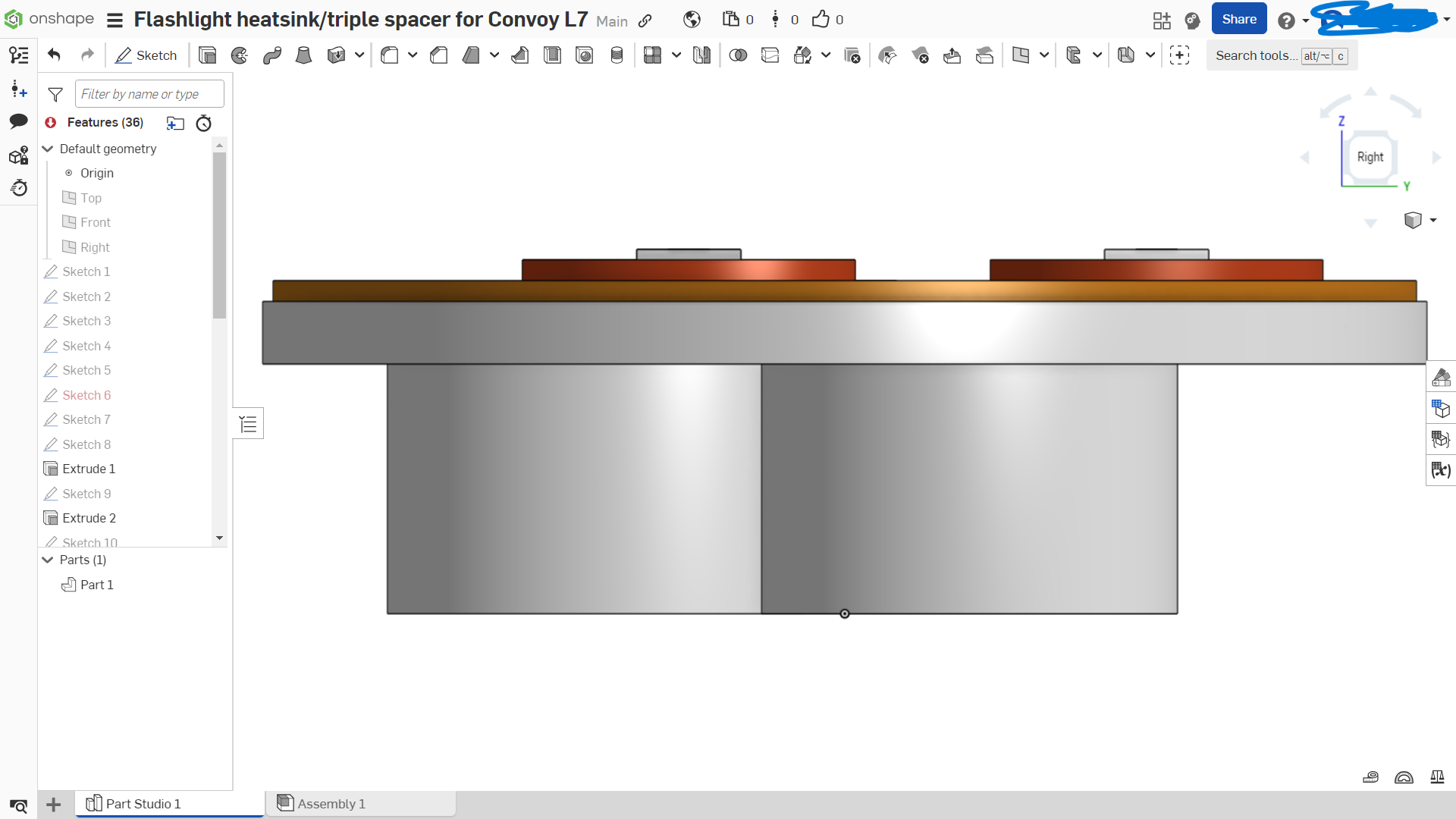
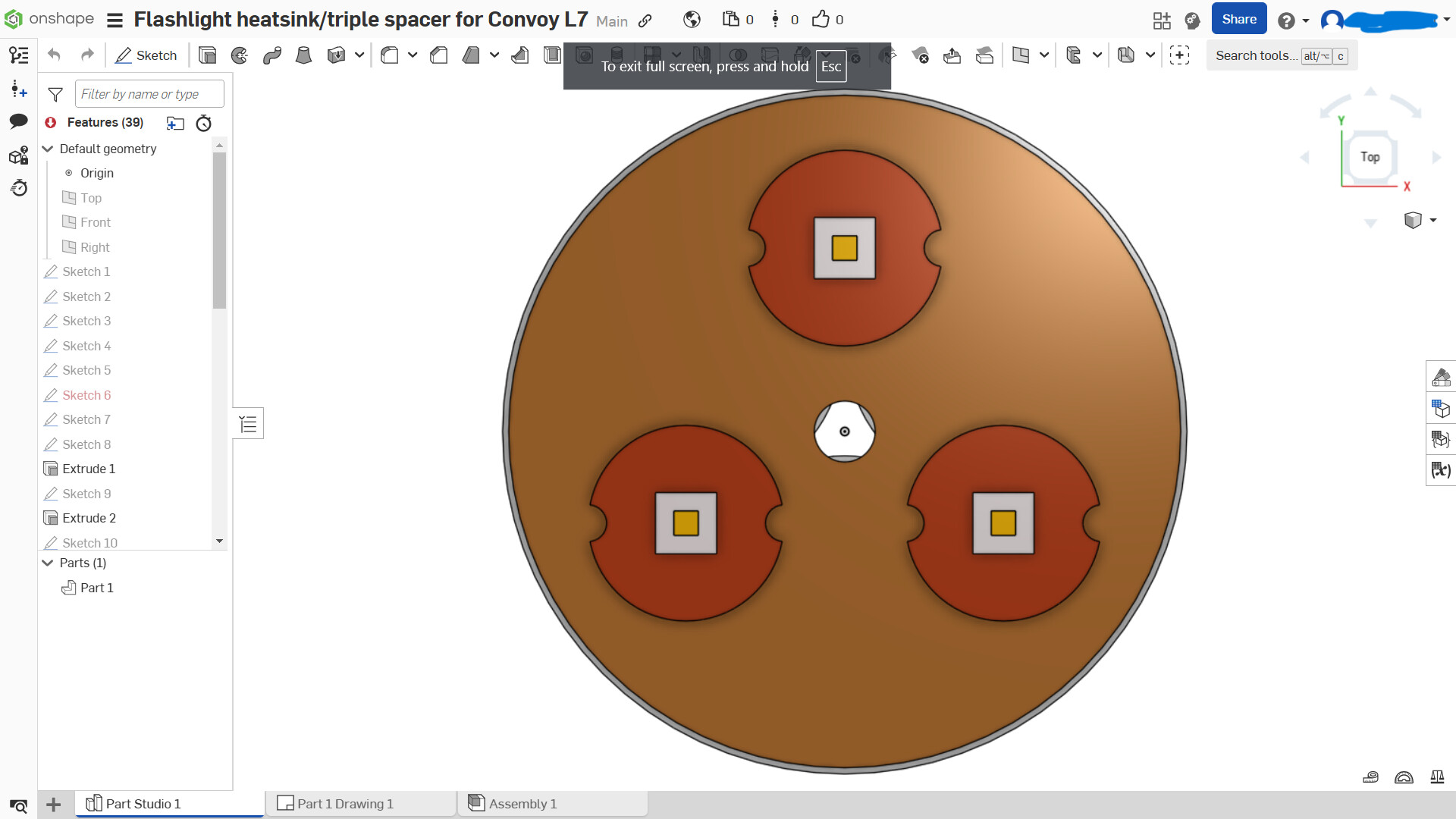
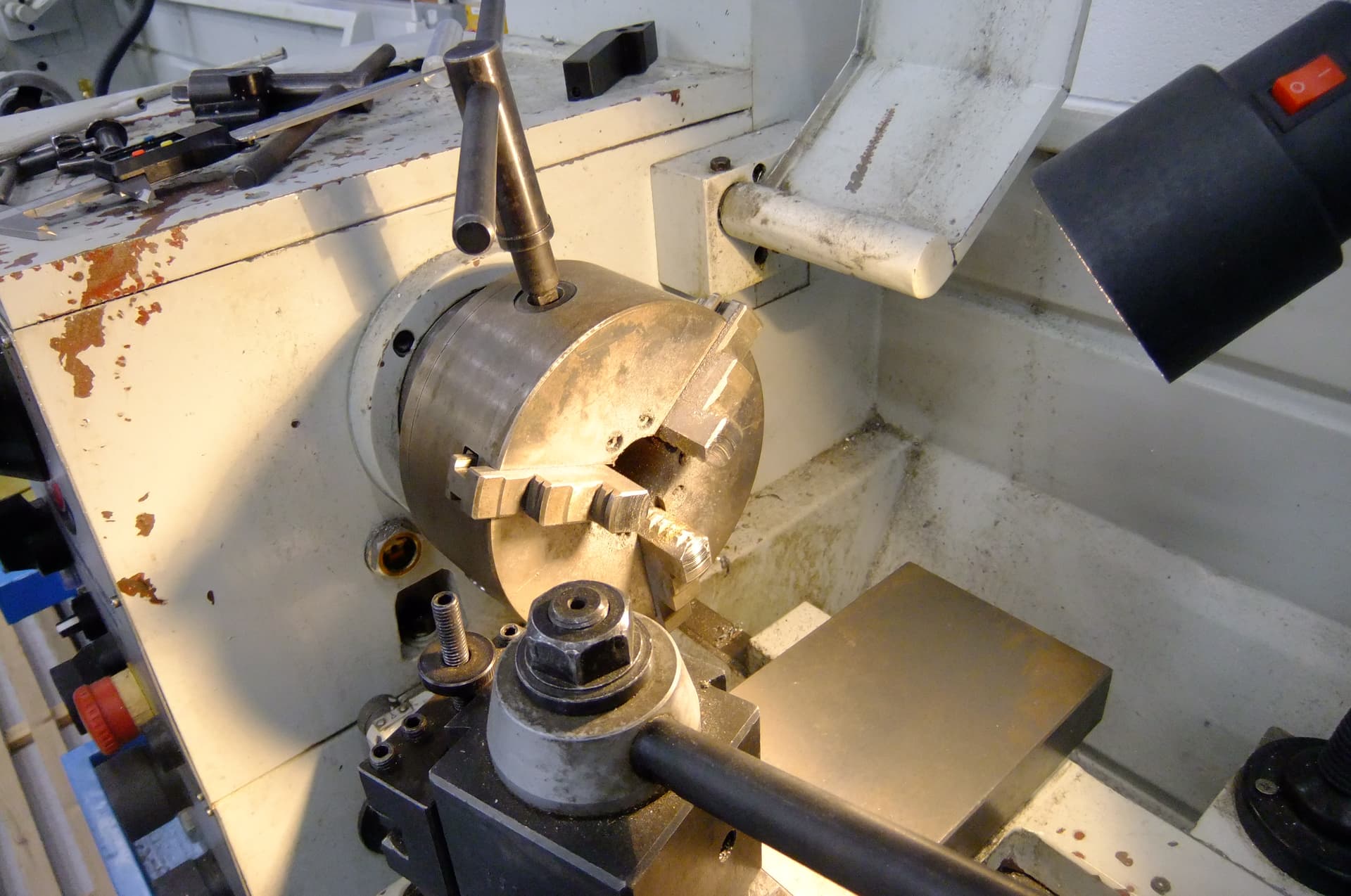
So my plan is this, create three aluminium bars and connect them to the top plate (using countersunk bolts). the center hole is used to run the wires to supply the LED’s with power. The brown circle you see in my design will be cut out of copper and the LED’s will be soldered on for optimal heat transfer. Ok, enough explaining done, lets make it! Last year I forgot to include photos of the actual machining process, this year that will change.
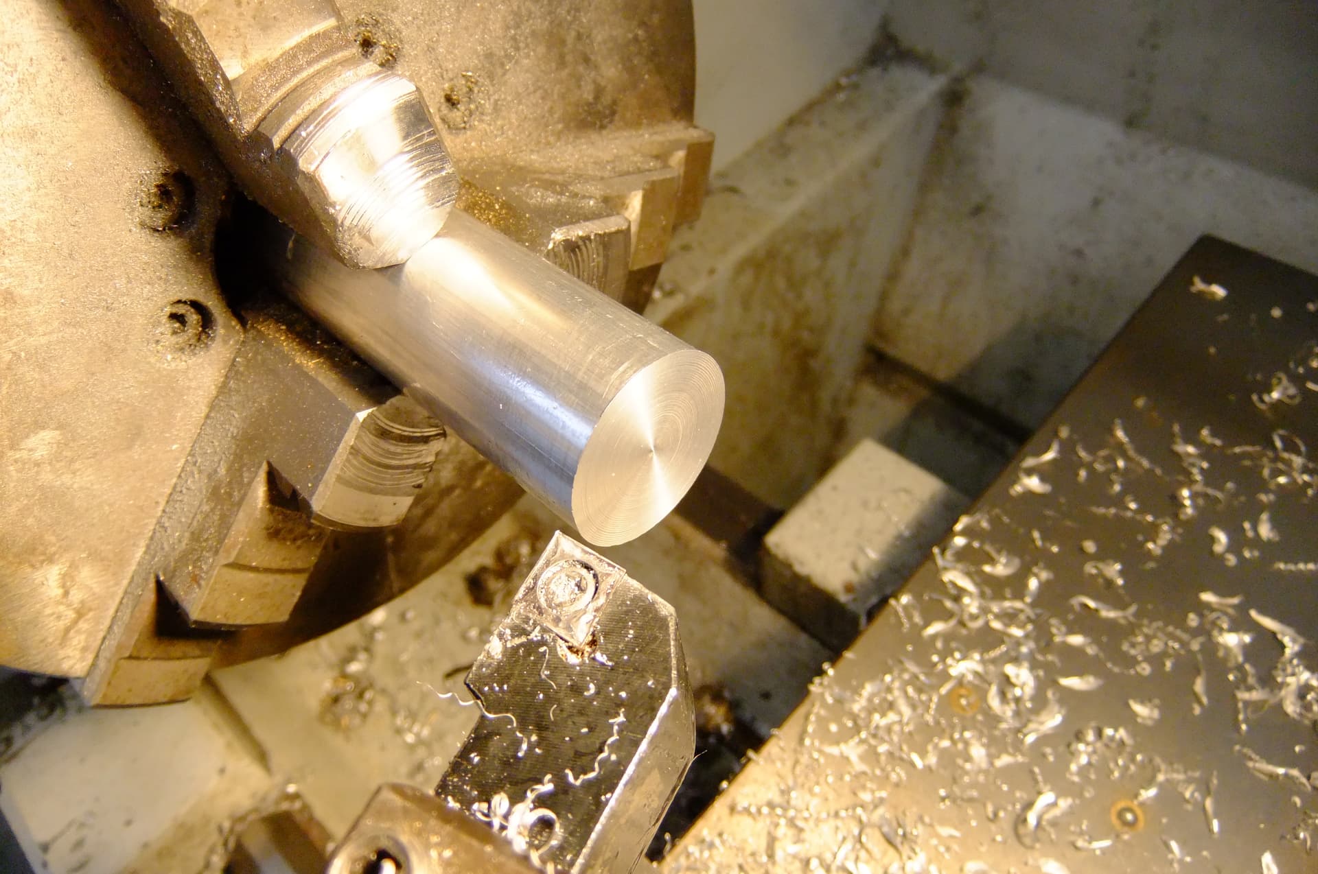
Firstly, I began by facing off the bar (creating a fresh flat surface on the end)
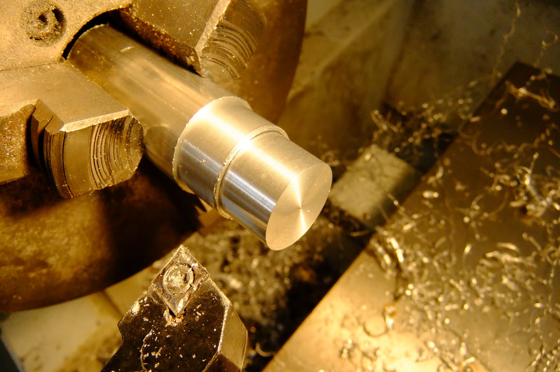
Next, I begin parallel turning to reduce the diameter of the bar to the desired 20mm. I also marked out the correct length of 12mm.
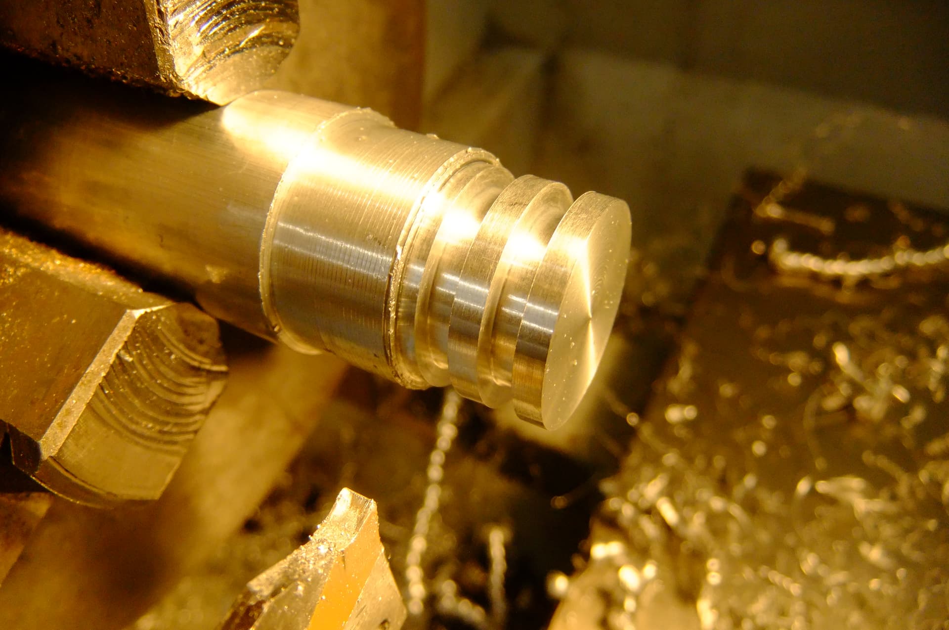
This step was unplanned, I used the parting off tool (used for cutting the part at the end) to cut heatsinking ridges partially through the bar. This increases surface area in contact with the air and hopefully takes away the heat from the LED’s.
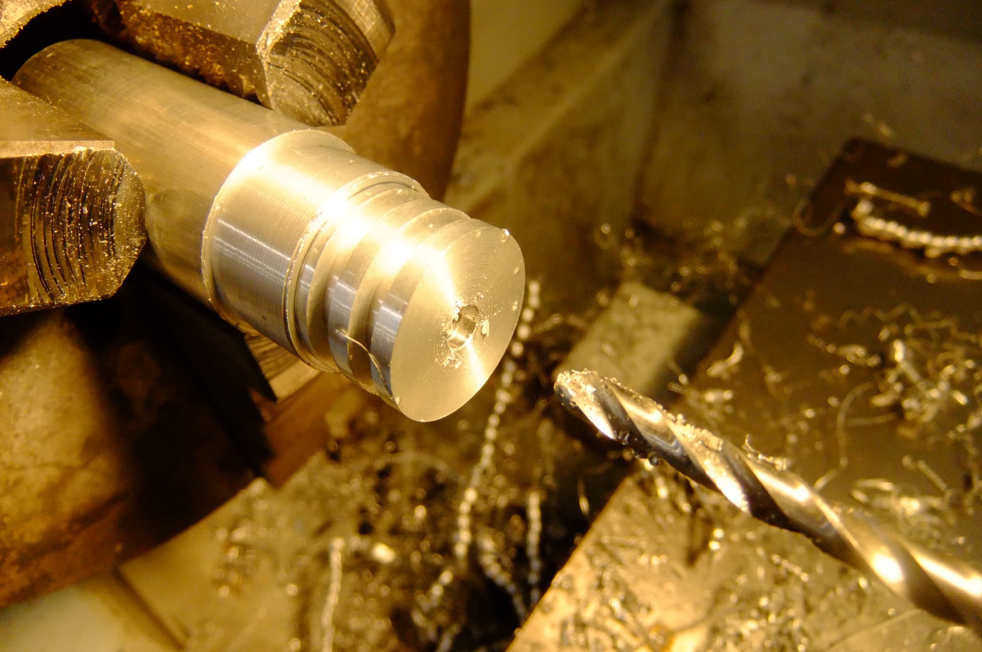
Lastly, I drill a hole using the lathe’s center drill to make a hole through the bar. It is diameter 3.3mm and will be used to cut M4 threads to secure it to my component.
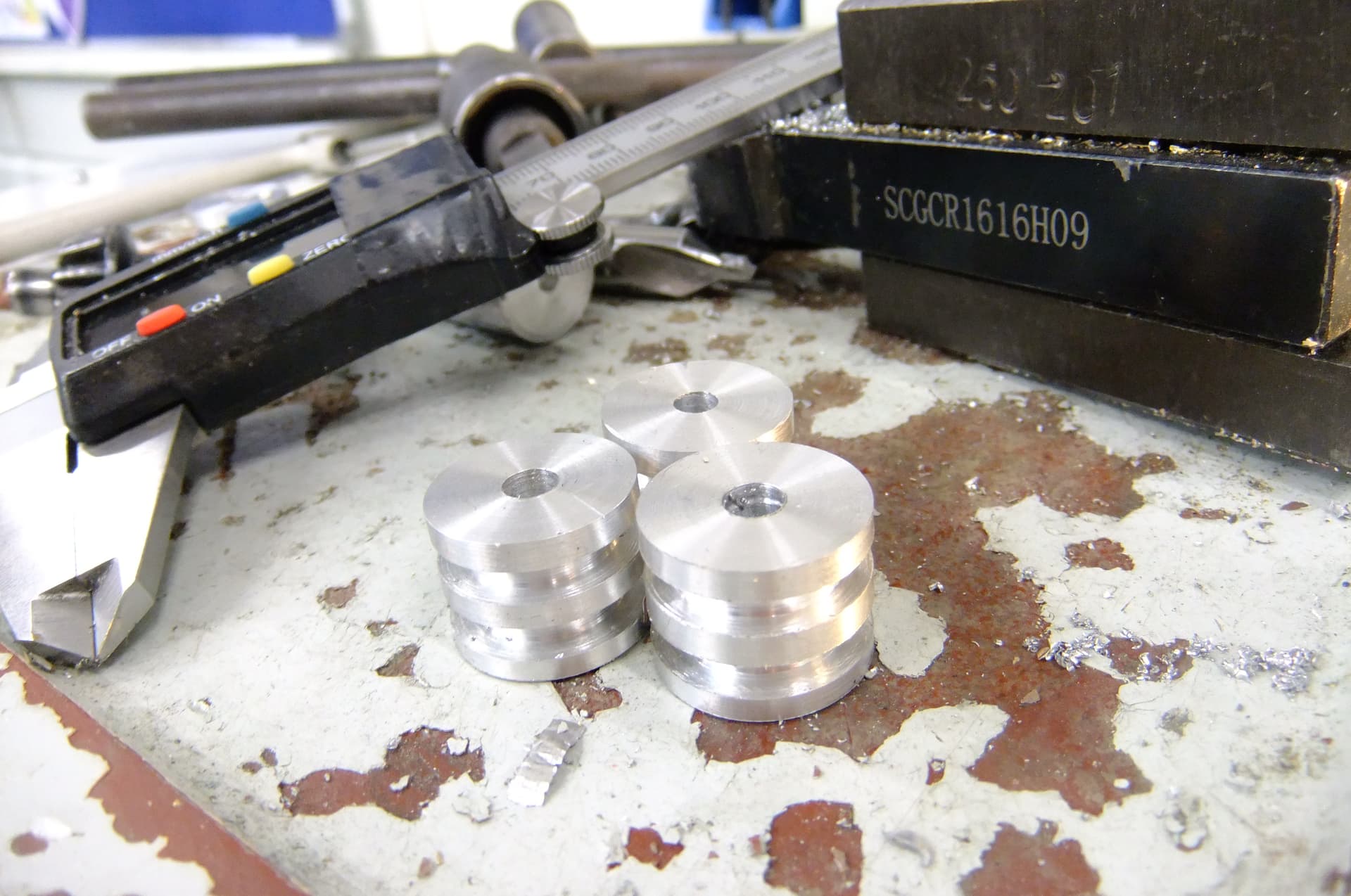
I repeated the process I have shown above 3 times and this is what I’m left with.
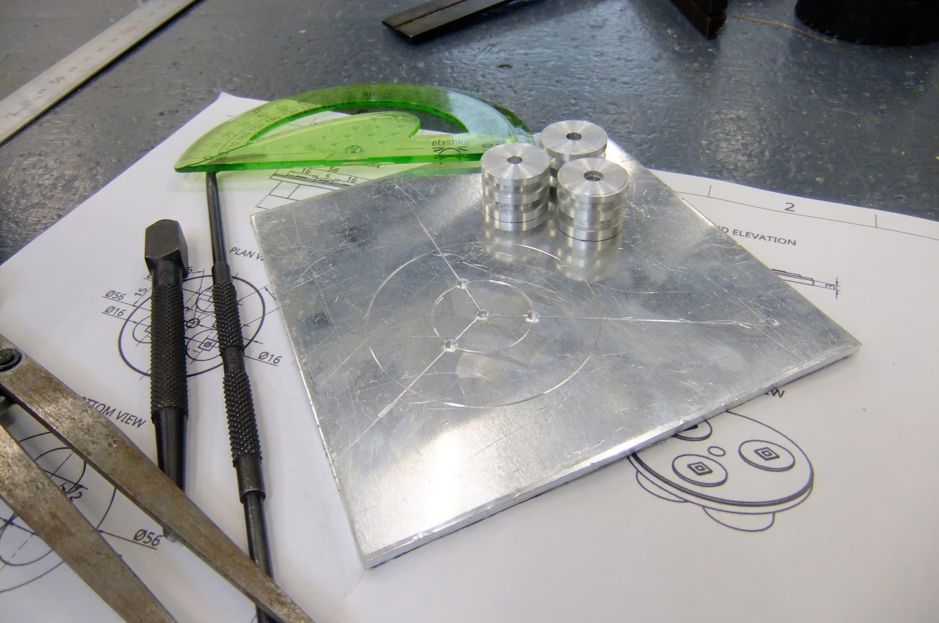
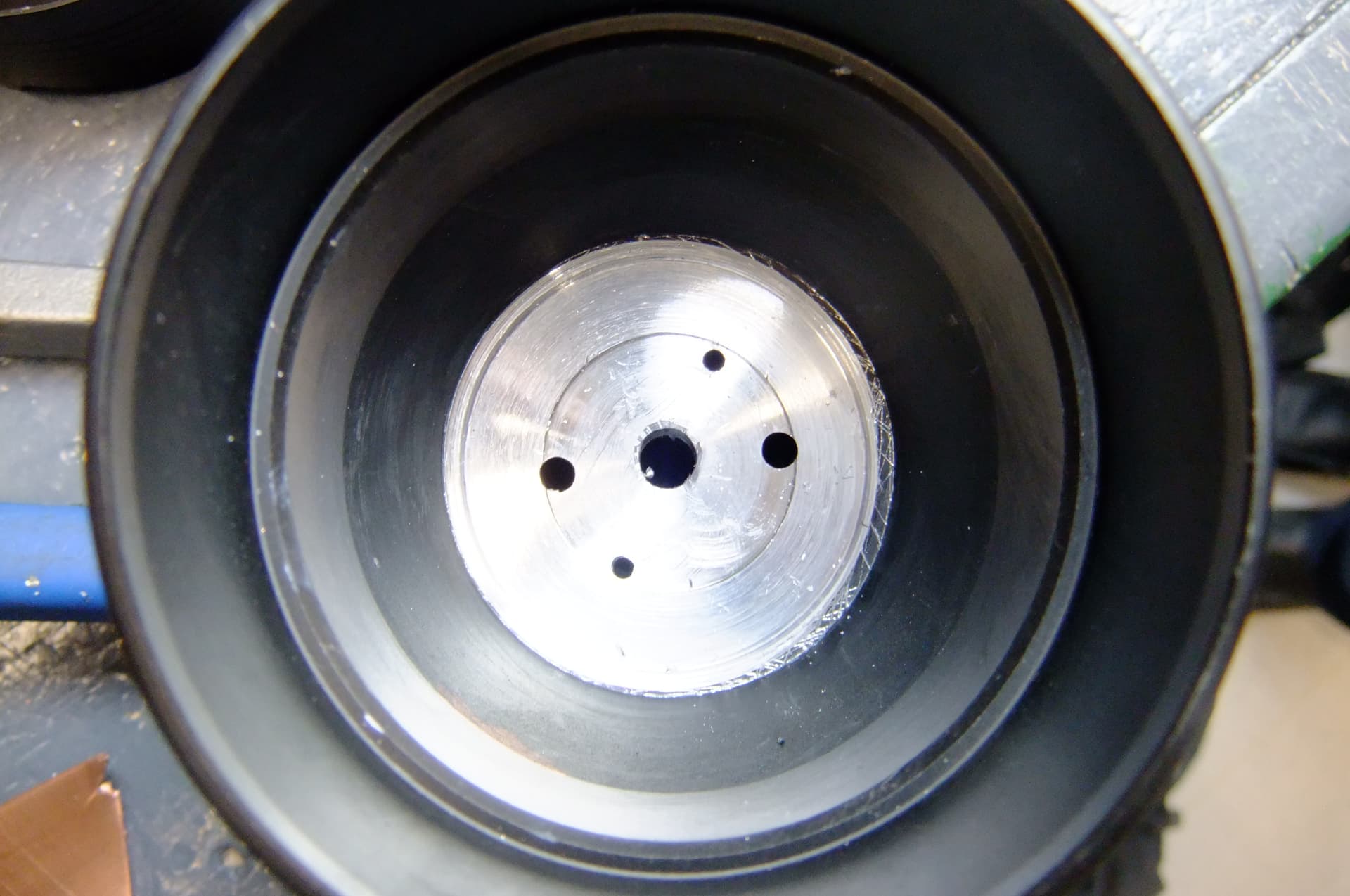
Now I need to begin making the round metal plate these bars will be fixed to. In order to do this, I used some basic hand tools for marking out my diameter. I divided the circle by 3 using a protractor. This is where I will drill bolt holes.
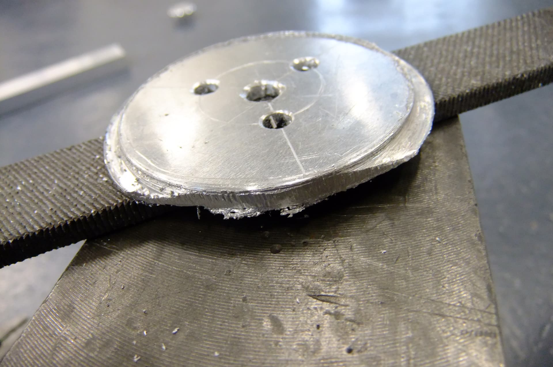
I began by drilling the smaller holes for the bolts. I used a hole saw for the drill with the correct diameter. As you can see, it left a horrible, rough finish. I filed off the burrs using a file until my part fit nicely down into the flashlight head.
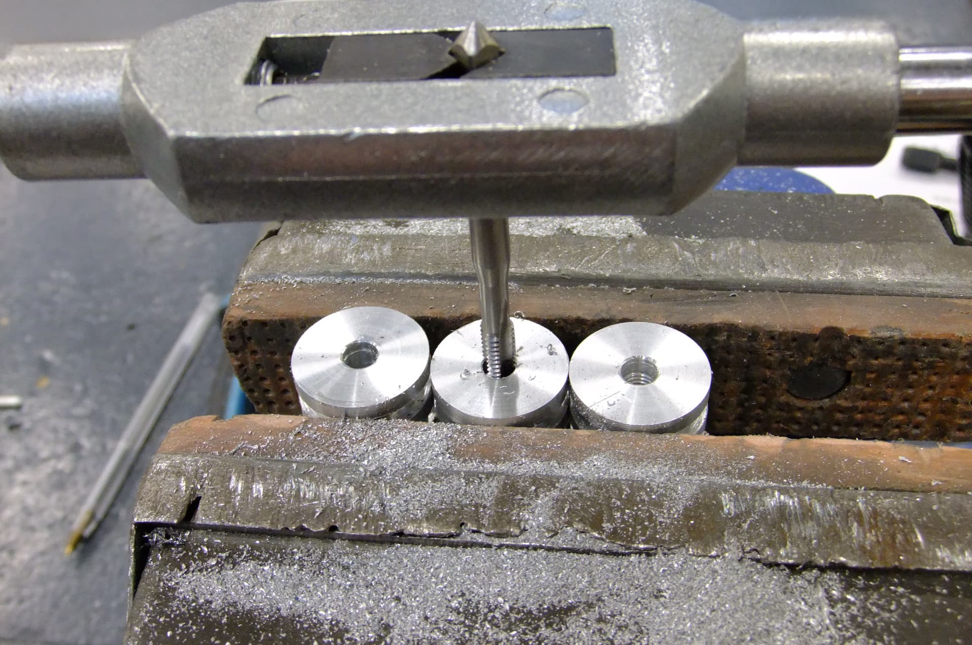
Next, I used a tap and die to cut threads into the bars.
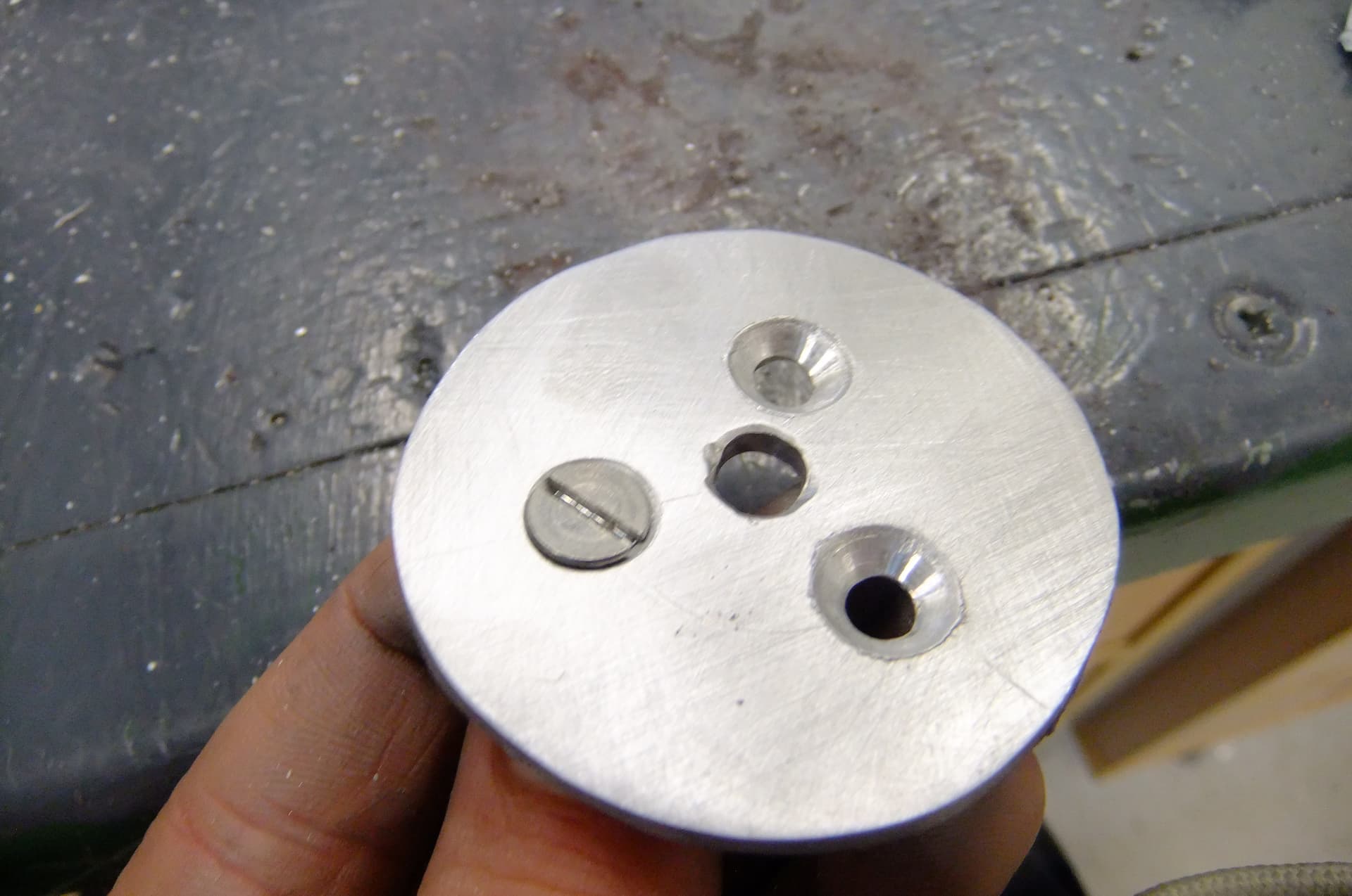
I used a countersinking bit for the drill to countersink the bolts in order to make them flush to the surface so that the LED’s can sit on top.
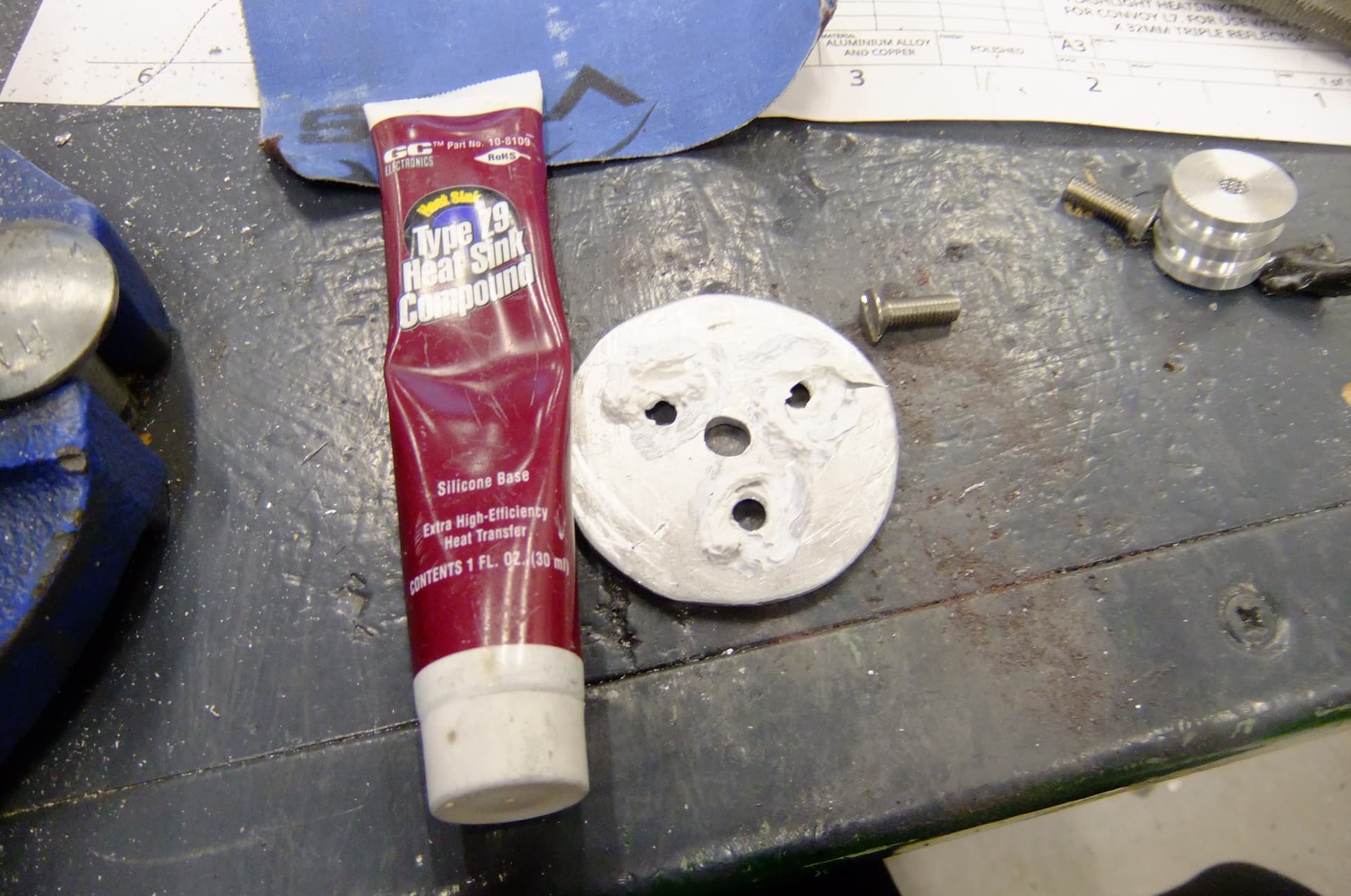
I added thermal paste to the connections between bars and plate to increase heat transfer.
Now my spacer component is finally finished!!
Now, I have to modify the actual flashlight host itself.
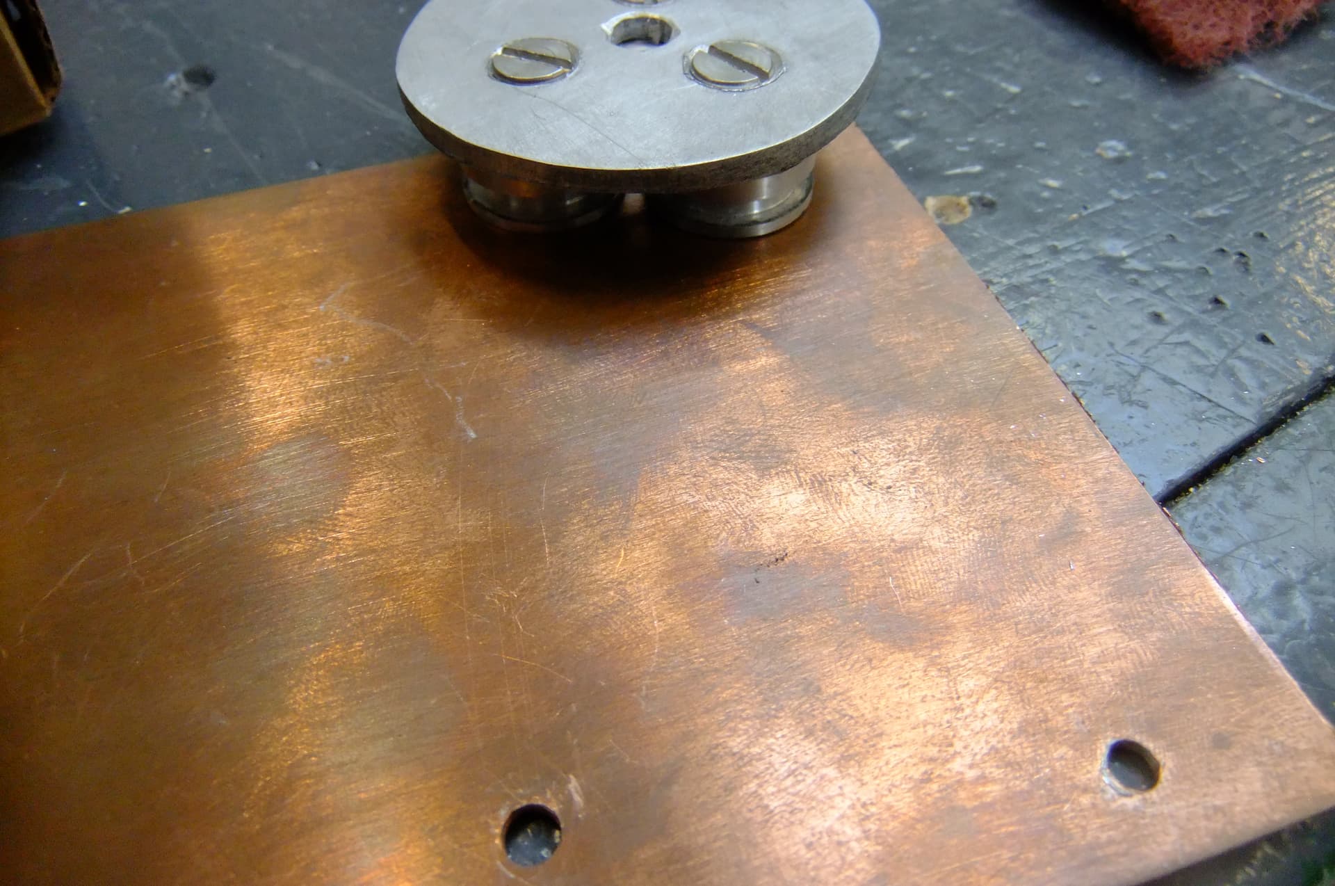
Do you see the way there is black anodization surrounding an aluminium center? Well that is recessed down about 1mm to center the stock mcpcb. All that has to be one flat surface or else my mod won’t work. Plus getting rid of that black anodization should increase heat transfer from my spacer component into the flashlight host’s stock heatsink.
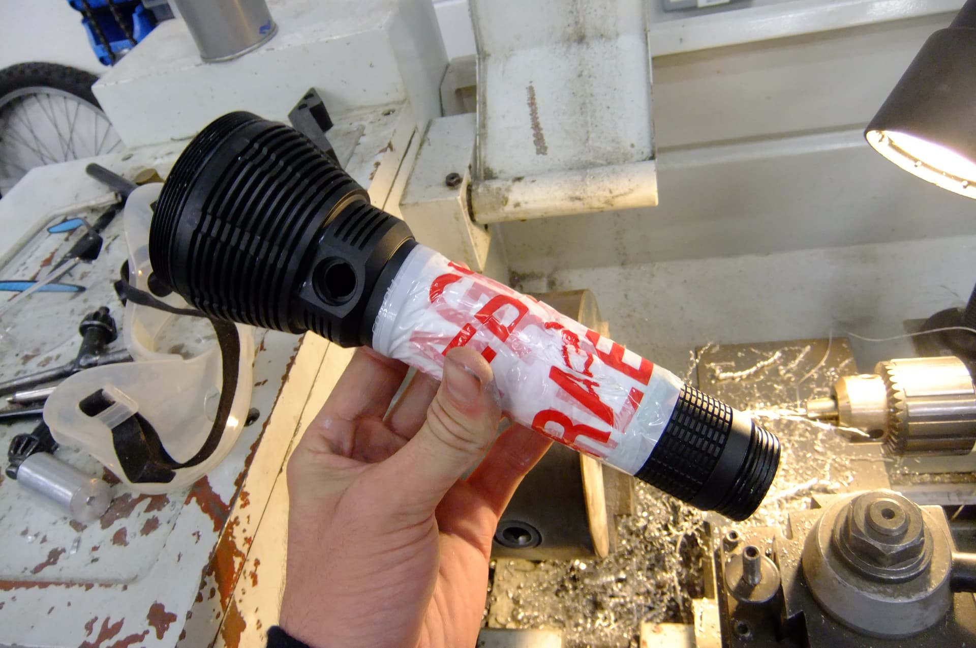
First, I wrapped my flashlight host in toilet paper to protect it. Then I added tape to hold the toilet paper and protect the host some more.
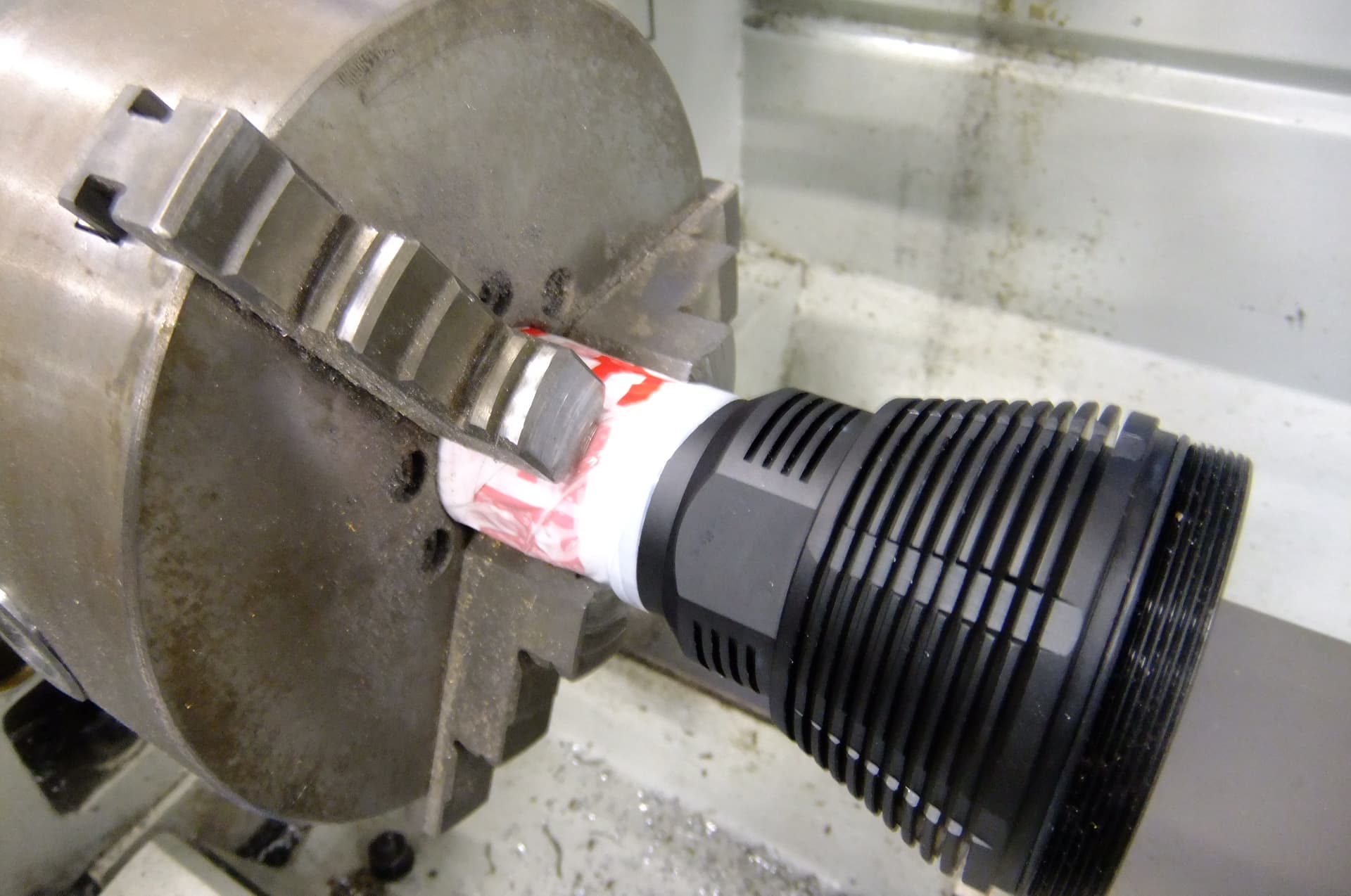
I have to admit that I absolutely hated this part. I put my entire flashlight host into the lathe chuck. this was hard to even watch, imagine putting a brand new, shiny flashlight into something like a vise that could easily damage it. Also I was afraid that the lathe spinning will destroy the threads between the head and battery tube (it was perfectly fine afterwards.)
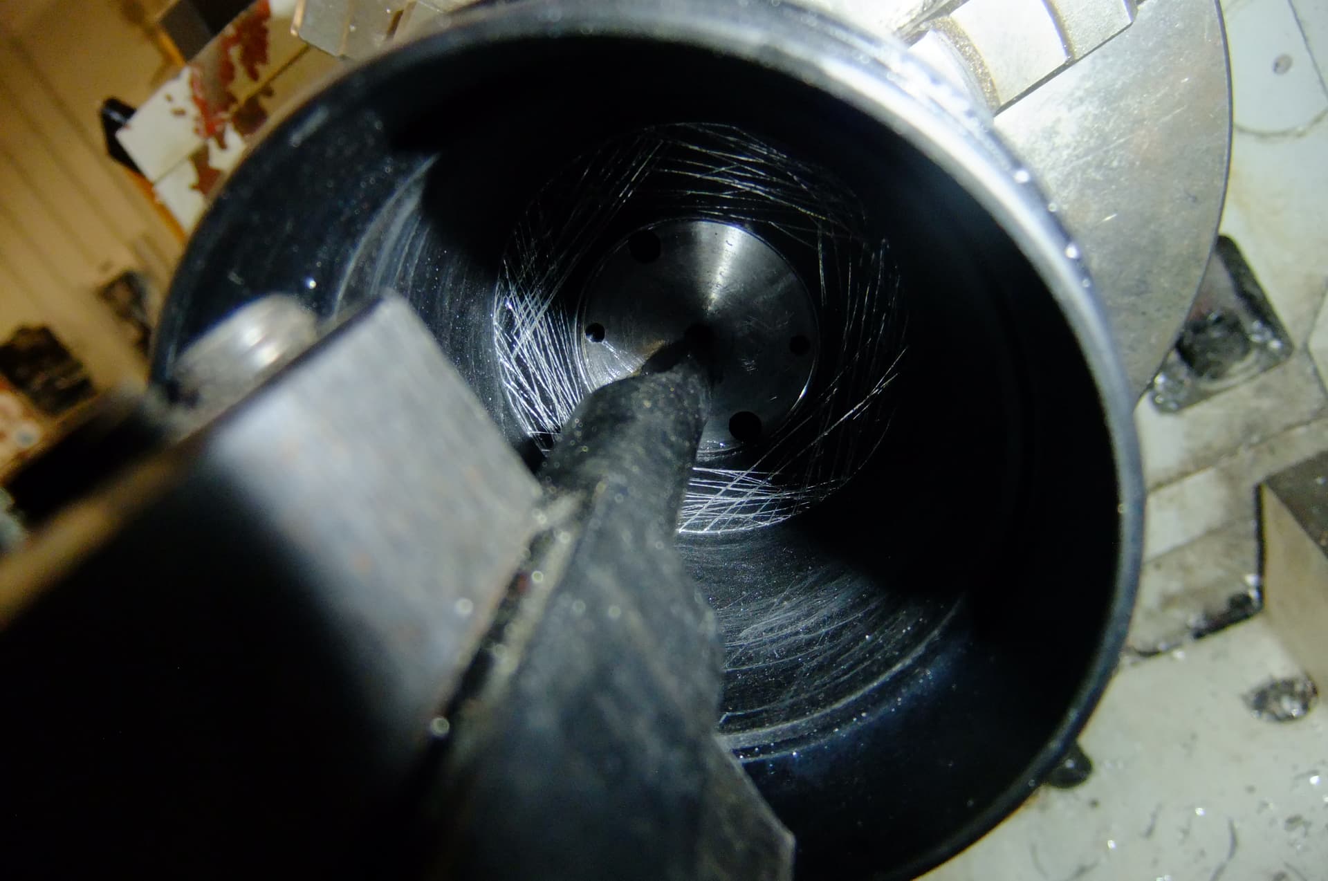
Next, I used the lathe’s boring tool to remove that ridge. ignore the scratch marks where I was trying to sand the anodization off by hand first.
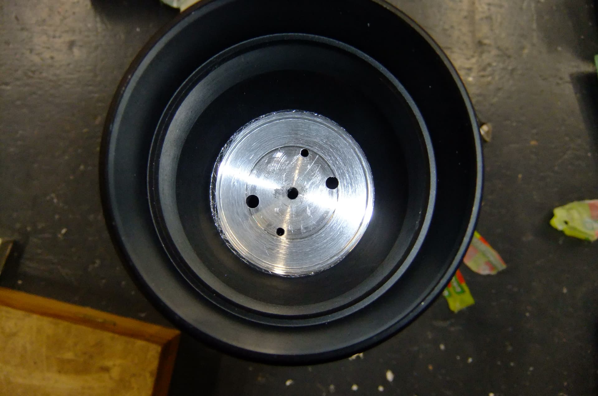
This is what I have achieved, a nice flat surface. I ended up having to go again as it wasn’t the nicest job and the flashlight wasn’t perfectly centered due to the toilet paper. I also began drilling a hole to route the wires up through.
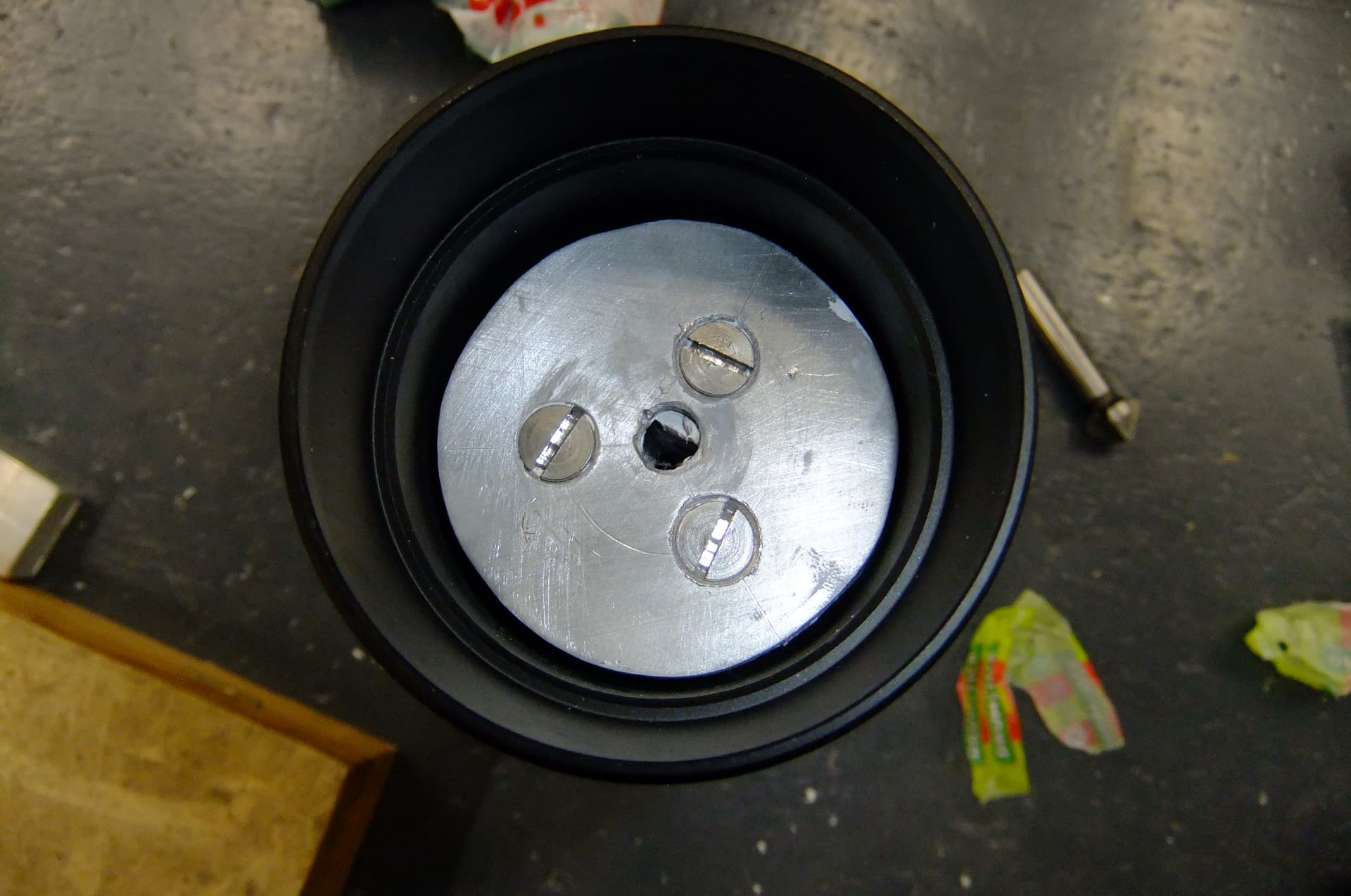
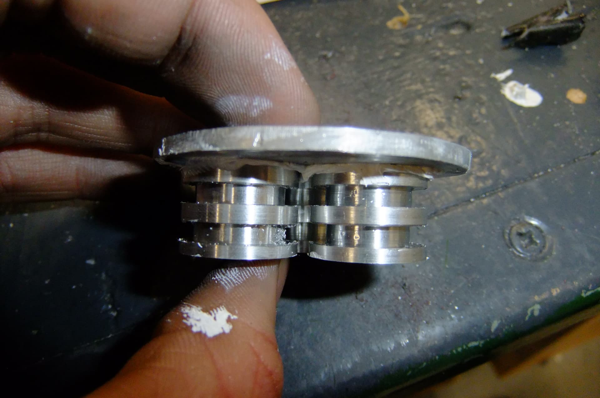
This is what my spacer component looks like inside the flashlight head.
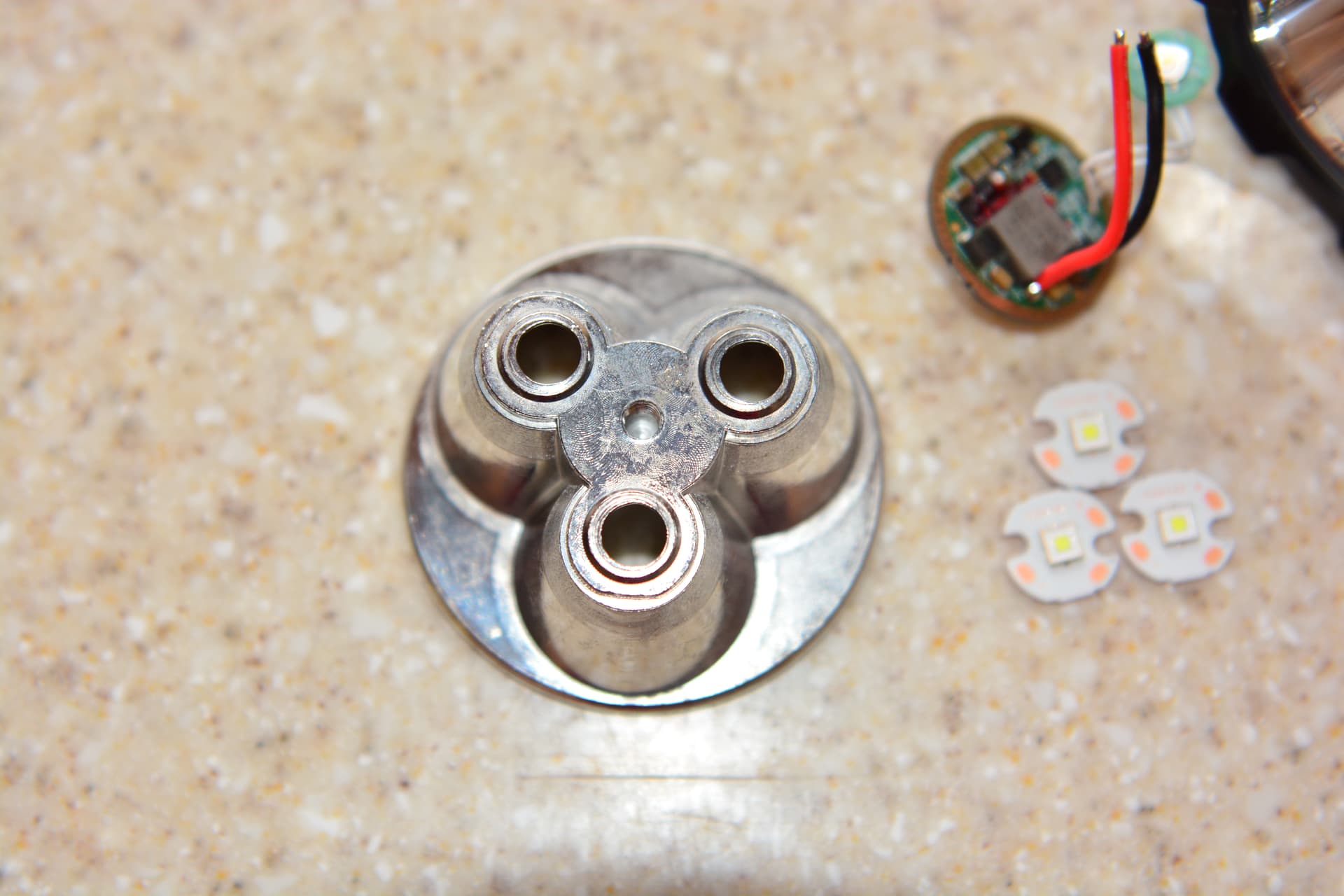
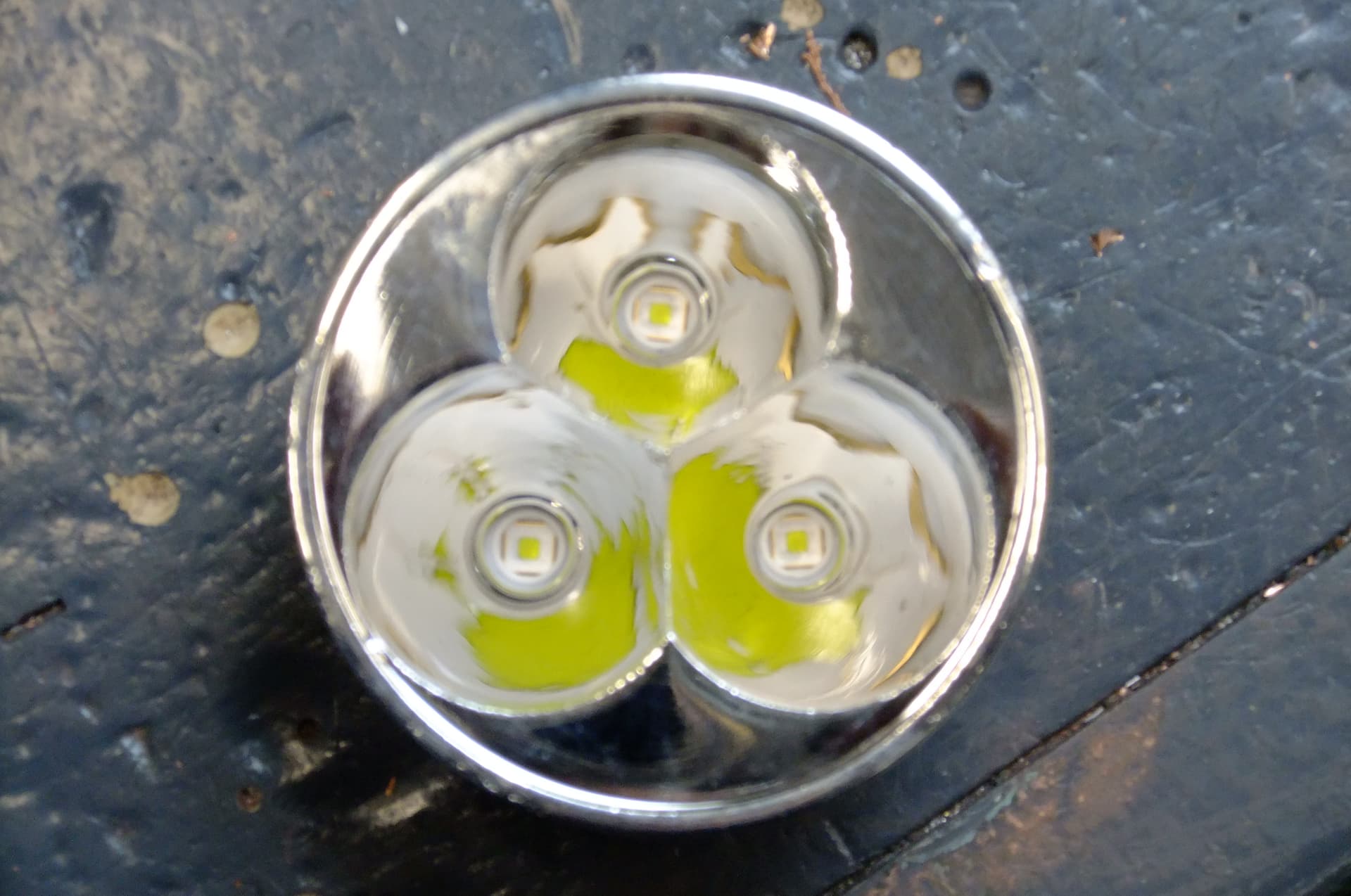
This is the reflector just sitting loosely inside the flashlight head. It looks really good and the flashlight head can close fully.
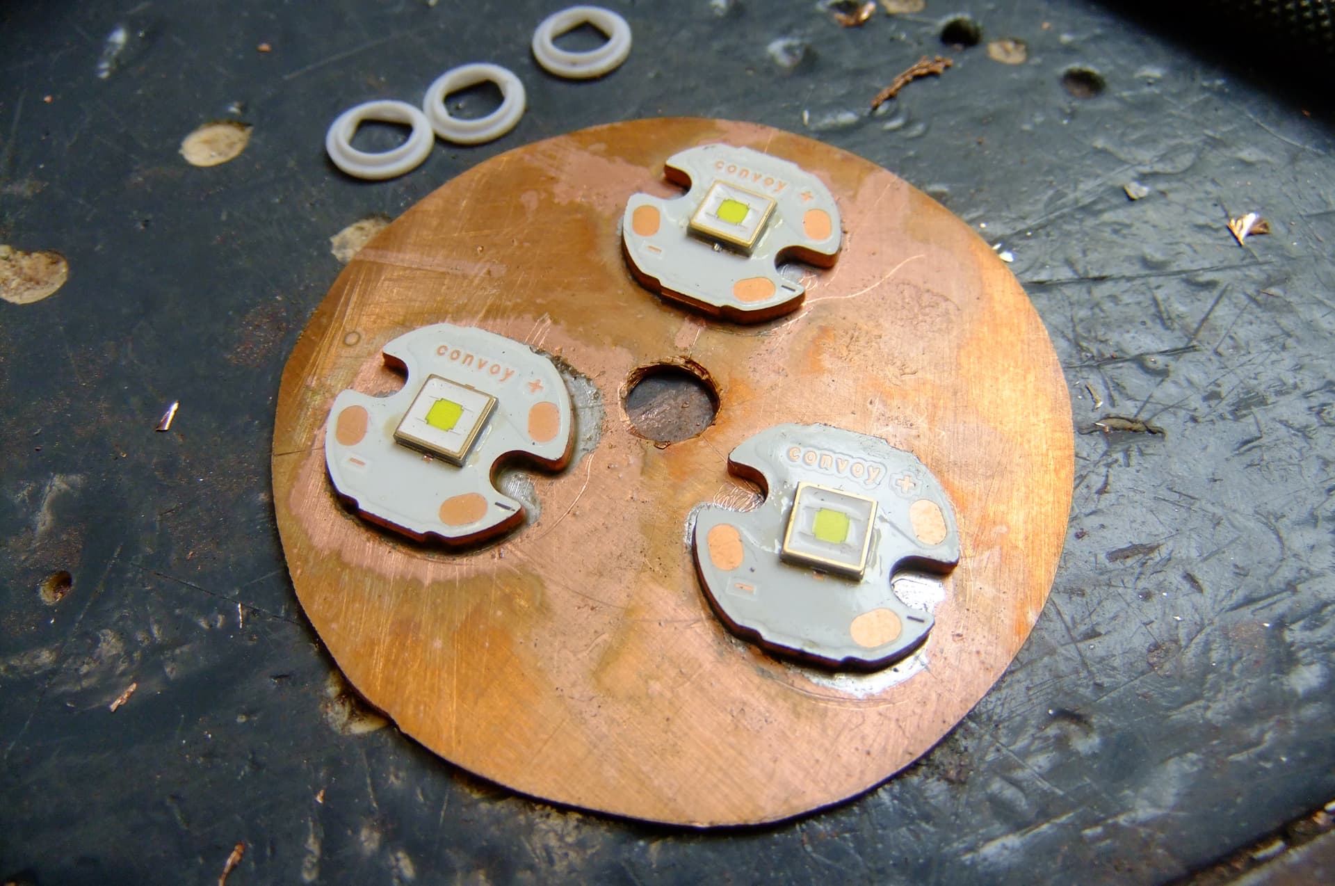
Now it’s time to make up my own ‘‘MCPCB’’. This will simply consist of three small MCPCB’s soldered to a circular copper plate.

My piece of scrap copper looked absolutely disgusting with corrosion. I began polishing the copper with fine grit emery paper. Then I traced out my design by marking out the diameter of the circle and dividing it into 3 equal sectors. Then I marked the positions of where the MCPCB’s will go.
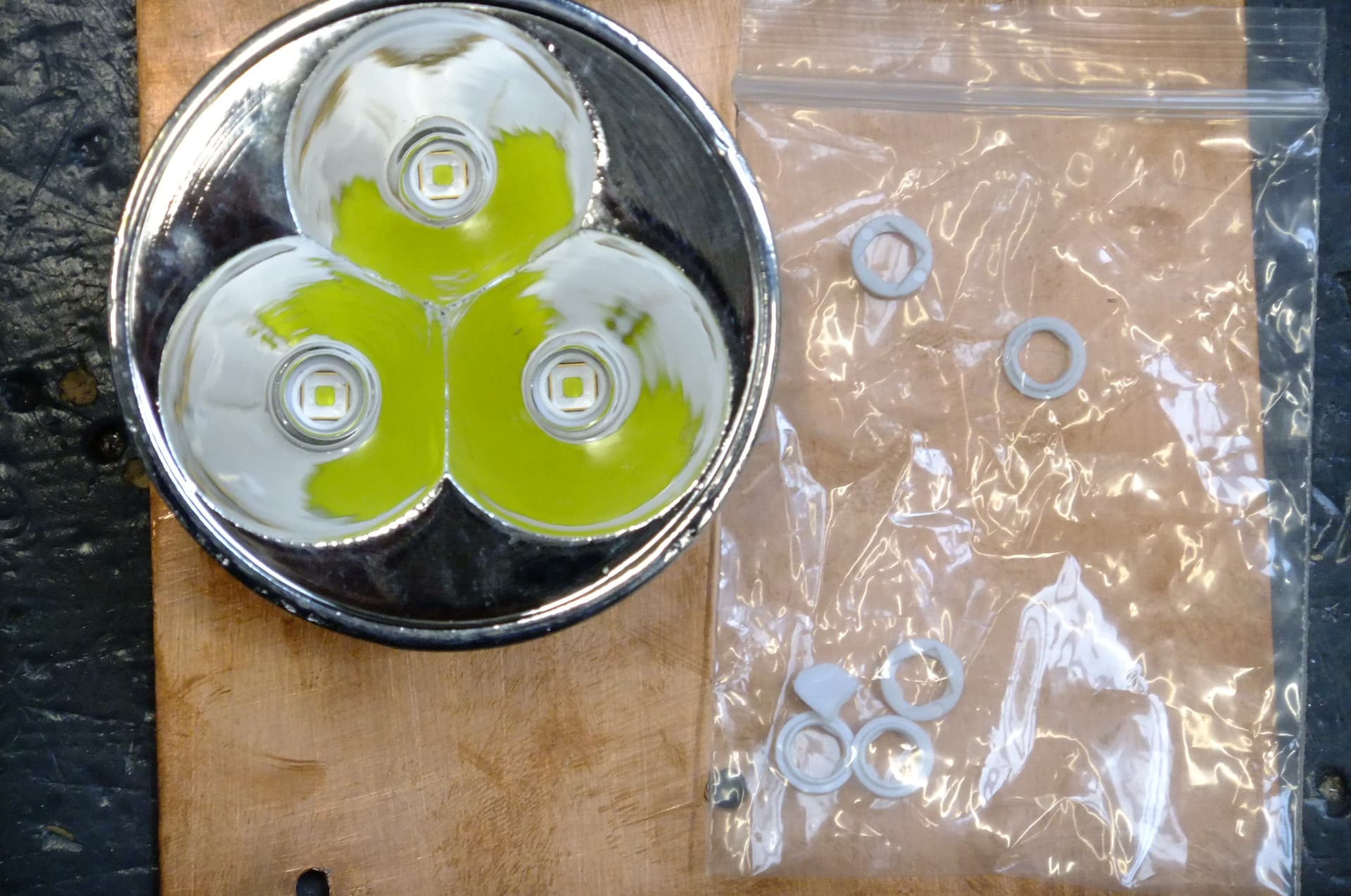
Here is my flashlight reflector just sitting on the LED’s in position. I haven’t soldered anything yet, just checking the spacing and it seems perfect. I also bought 5050 LED gaskets.
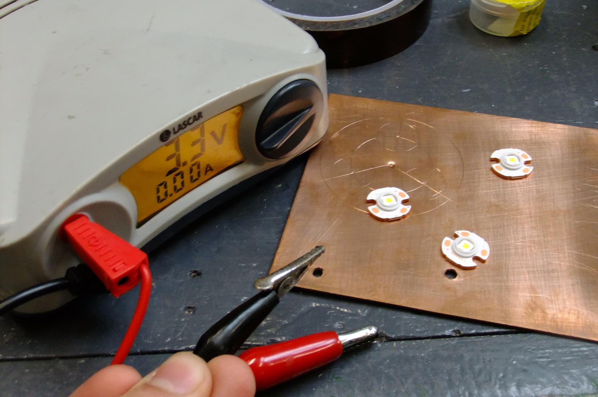
Testing the LED’s on my power supply. They are all OK.
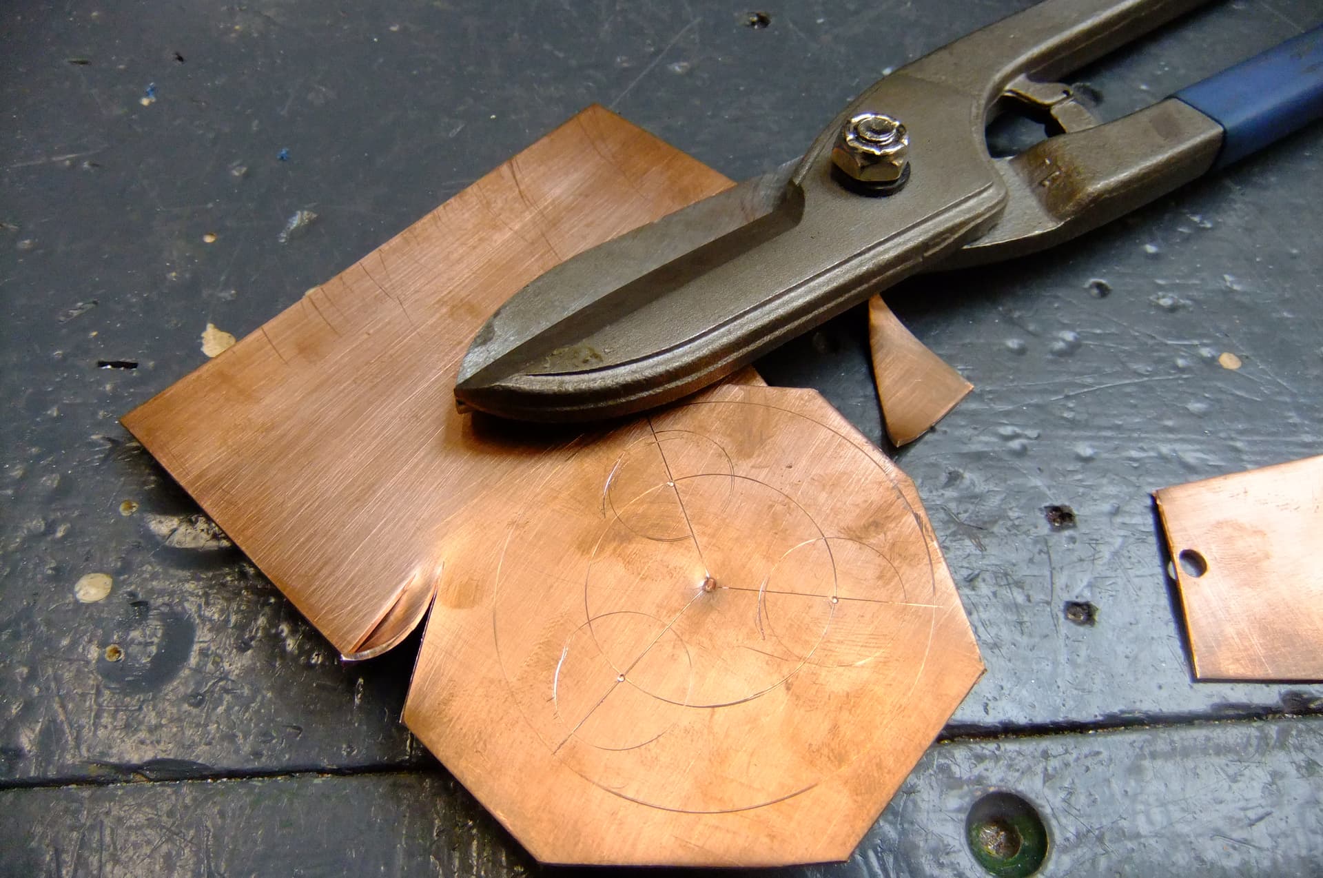
I was able to cut the copper using a pair of tinsnips as this metal is only 1mm thick. It is also malleable and easy to cut.
I went again on the lathe to do a better job. I also drilled a bigger hole for the wires.
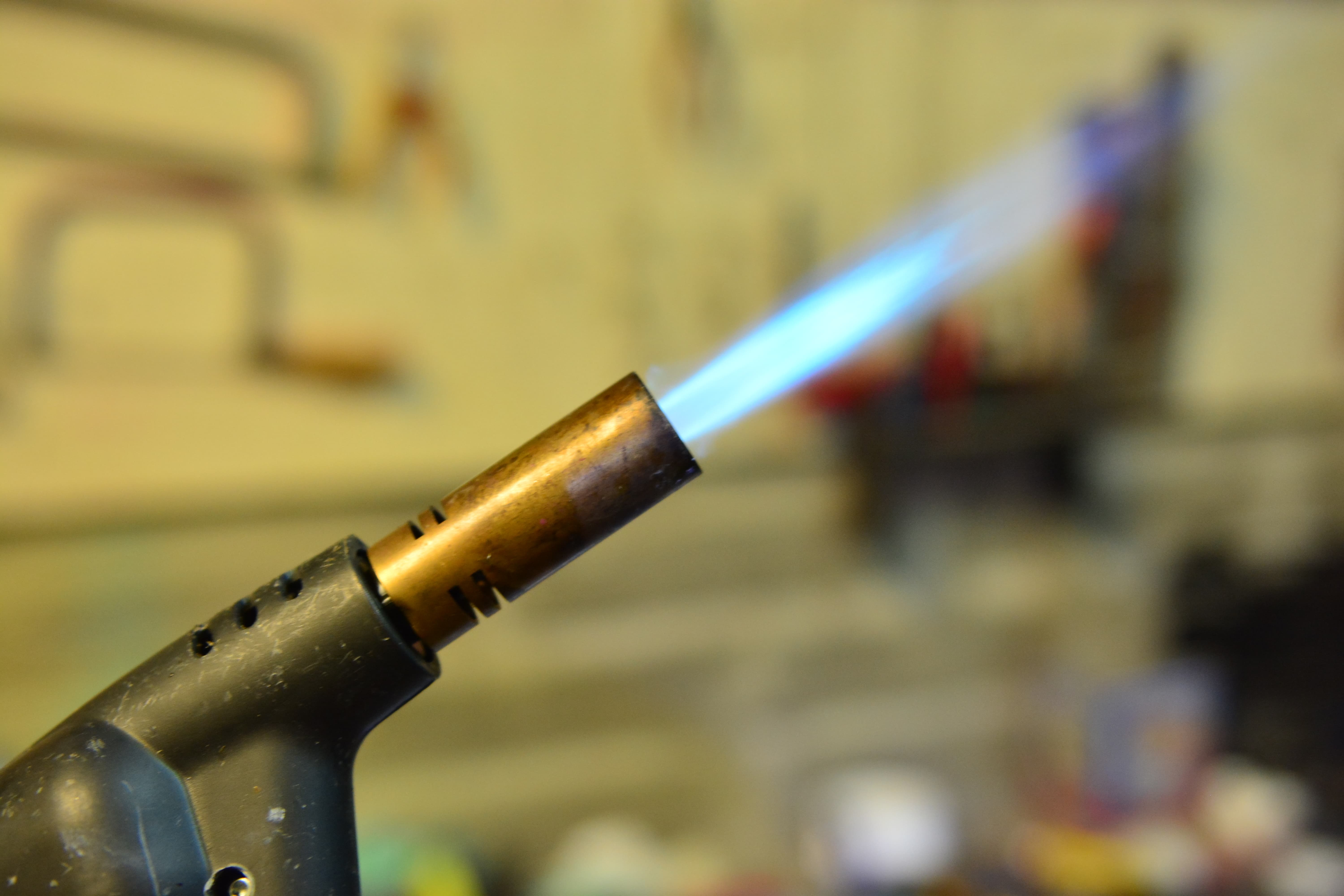
Now its time for the soldering. I applied some solder paste which melts at 183 degrees to the MCPCB’s, then I grabbed my propane gas torch and began gently heating the copper plate from below. I held the gas torch quite far away because I was afraid of frying the LED’s because the datasheet says you are only allowed to reach 245 degrees. The problem was my gas torch is 2000 celsius. This is the only piece of heating equipment except for soldering iron which I have. Anyway, the solder melted quickly and I tested the LED’s. All still working.
Not bad at all! They seem well fixed on and still centred nicely!
The reflector still seems to fit on nicely. That’s all I have for today, can’t wait to get this thing wired up and see if it works. Should be an absolute beast of a light!
3rd update
I’ve been quite busy lately but finally got a chance to begin doing more work on the light. At this stage, the next step will be assembling the electrical system of the flashlight and getting everything wired up, but first I want to explain what my plan is: I will be using the convoy 30mm 3V 20.5A buck driver. I didn’t have much choice as previously mentioned, due to the flashlights large diameter and the dual switch set up. There were a couple other options such as a 6v XHP70.x driver and a GT-FC40 12v driver that are compatible with this light. I chose 3V because this is the Vf of my SFT40’s. Now, according to Kirchhof’s current law, if you wire some components in parallel, the voltage stays the same and the currents add up, and if you wire some components in series, the voltages add up and the current remains the same. Now obviously this means I will have to wire my LED’s in parallel to get the 3V required and the currents of the three leds added together = 20.5A which gives me about 7A per LED. (Maximum is 8A). Its worth noting the batteries in series are 6V stepped down to 3 due to the buck driver which means my vapcell K62’s should meet this light’s current demands. Because P=VI, this means I will get over 60W of total power in the flashlight. This should be incredibly bright!

Time to see if it works, here I have everything ready to begin wiring it up.

A close up of the driver I will be using
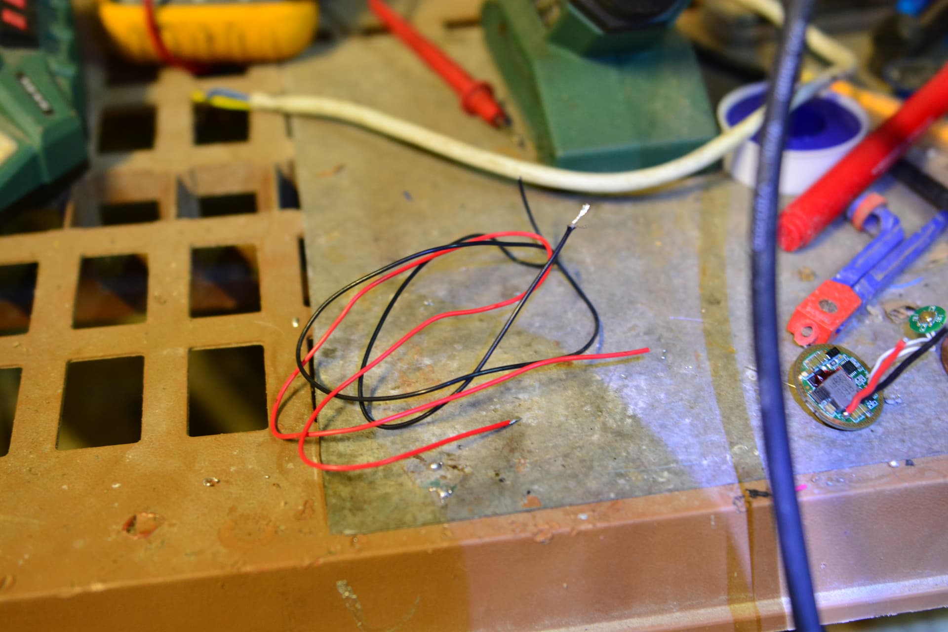
Some positive and negative wire which will be what I will use to make the electrical circuit. First I have to add longer wires to the driver because there is no way the stock wires will fit up through my spacer component.

The driver with new wires fitted into the flashlight host. I also fitted the E-switch. It was an absolute pain to tighten down the tiny ring to hold down the switch boot because I’ve no tool for it. Anyways a tiny pair of scissors done the trick.

Here I have began the wiring for the three LED’s wired in parallel. The hole in the centre allows me to pass up the driver wires through to supply power. I managed to put everything together before I realized that I made a mistake somewhere. I clicked on the flashlight switch, and instead of any light, I heard an electrical buzzing noise that sounded like sizzling. Something is obviously shorted, possibly on the copper MCPCB substrate. Hopefully I didnt blow anything like the driver. The flashlight was on for only a split second. This is all I can write for now, hopefully this isnt failure. I will have a closer look at it see where the mistake is.
Troubleshooting
I had a look at what could be causing my short circuit. First I desoldered the LEDs and quickly found my problem. My solder joint was making contact with the copper substrate which shorted the driver. I then adjusted that joint and after supplying power to the LEDs in parallel on my power supply, all 3 lit up. I then tried soldering them to the driver and it worked, until I installed the reflector which triggered the same problem again, a buzzing noise. I instantly turned off the light and figured out that it must be the metal reflector causing this, so I ‘flattened’ down the joints with my soldering iron. Soldering was hard because the flashlight host and my spacer component absorbed the heat so effectively! Next, I added kapton tape all over the exposed solder joints. Next I covered the entire bottom of the reflector. This was tedious work with a small utility knife, and the tape kept sticking to my hands.
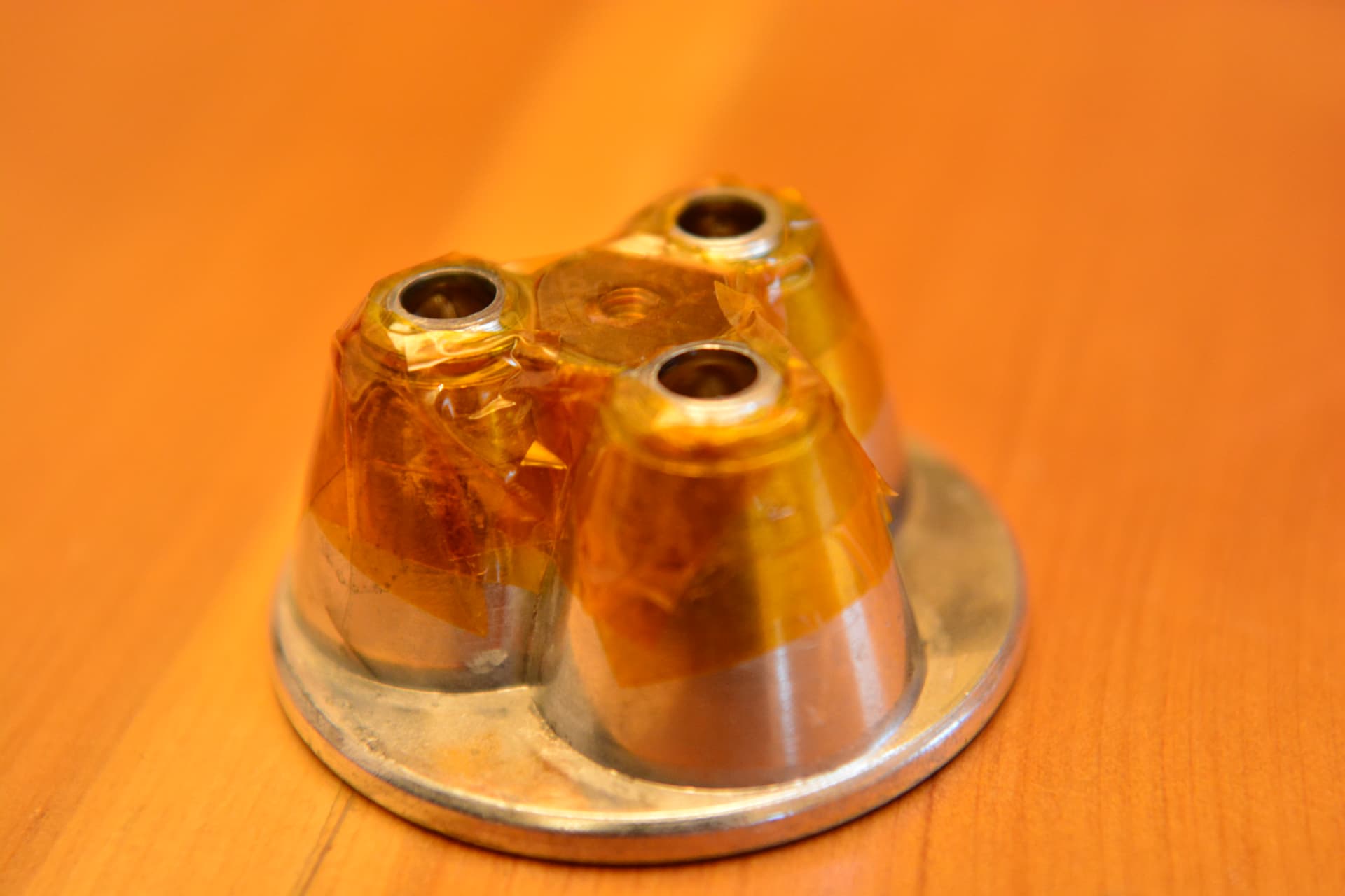
Here is the underside of the reflector covered in kapton tape.

I made sure to cover any exposed joints to prevent short circuits.
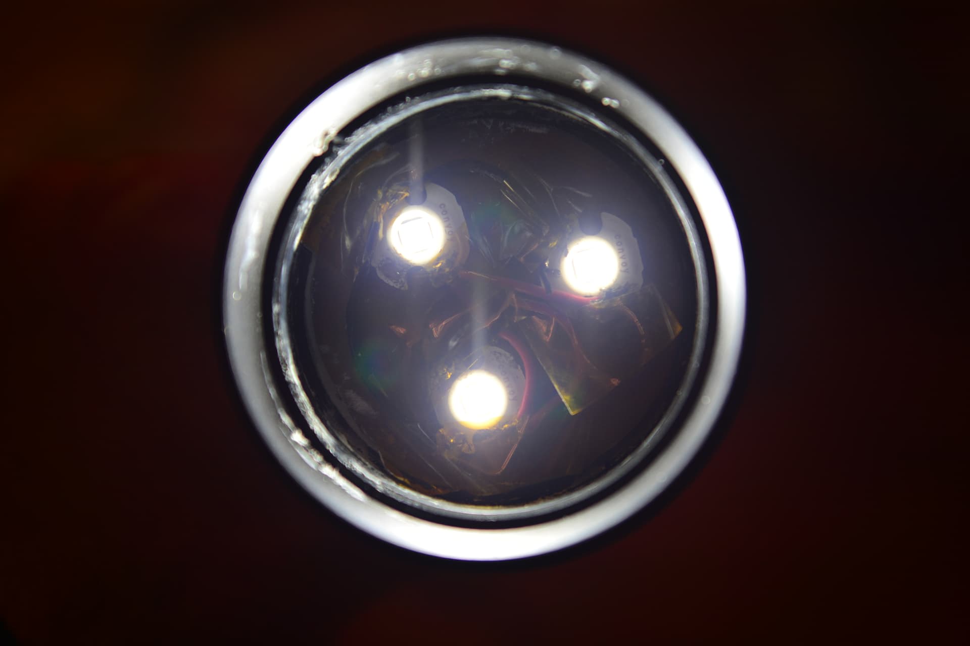
The flashlight does in fact work now. Luckily my driver circuit wasn’t fried!
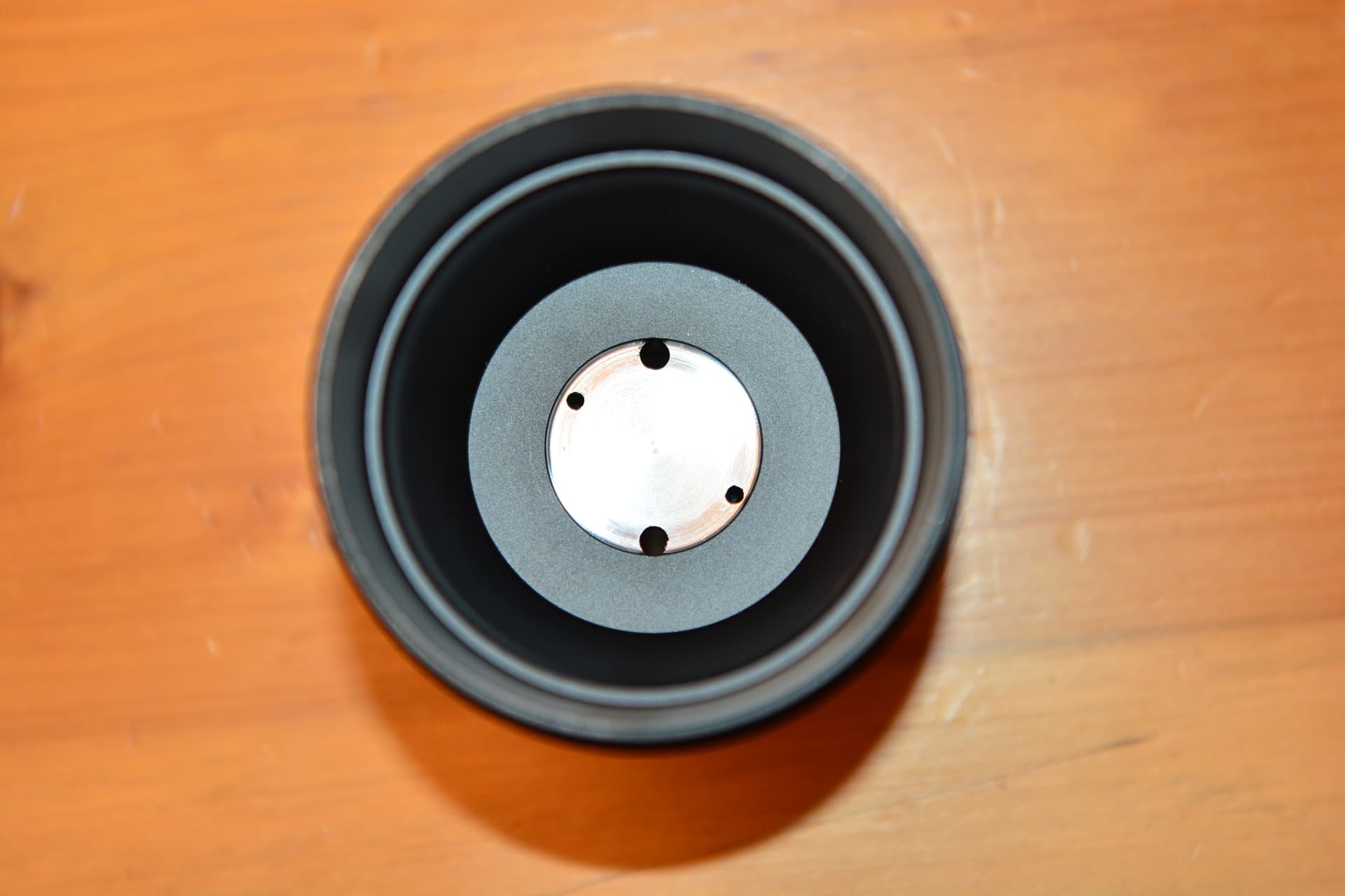
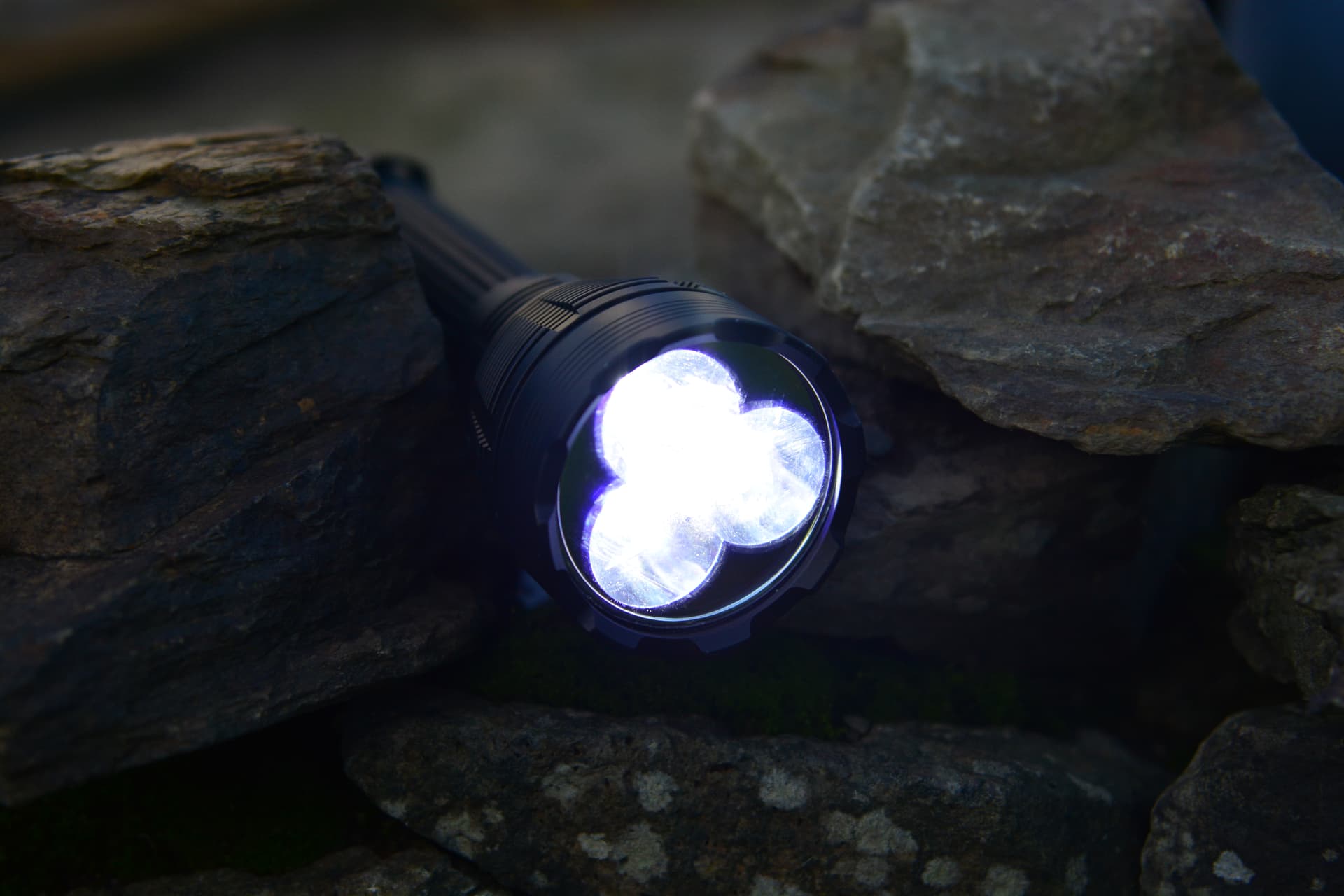
Here is what it looks like with the head, reflector and bezel tightened down.

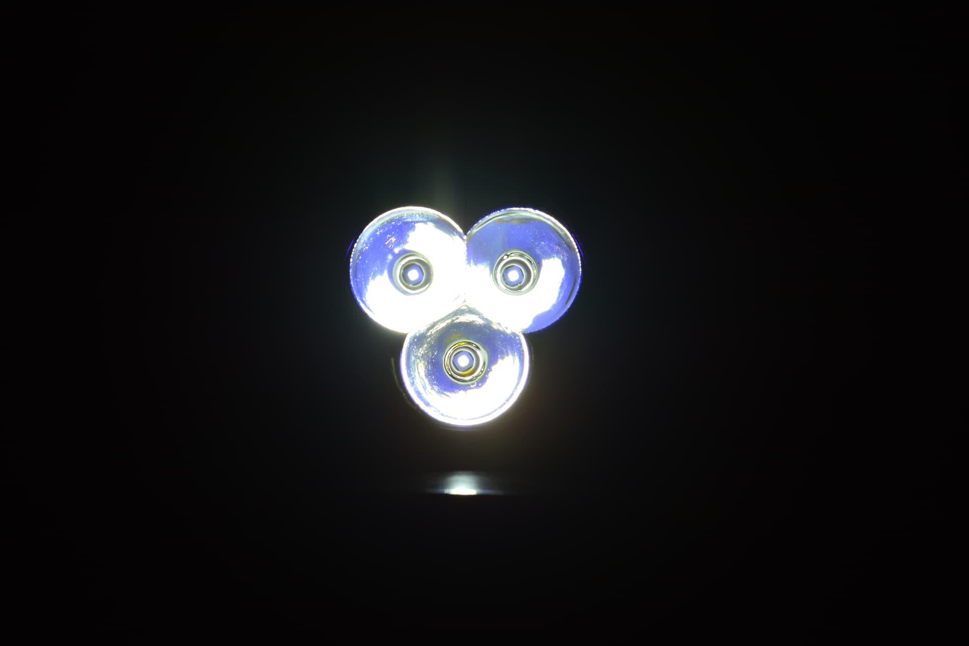
A quick white-wall beamshot. You can see the hotspot is very focused and also nice and round for a triple. There is also a corona visible as a ring around the main hotspot, but this doesn’t bother me one bit. Again, I would like to emphasize this is a mod focused purely on performance and will actually be used. What good is high CRI if the flashlight overheats and drains through batteries which in my case, might cost the sheep’s life if not found soon enough.


It actually feels great to have this much progress done already. I haven’t got much chance to use the flashlight yet, but one thing is certain, this thing is stupidly bright and the beam is so intense it almost feels like holding a light sabre from the movie star wars lol. I will take decent beamshots soon, and try to measure throw distance. I also want to estimate the brightness. perhaps even a video of the flashlight in use or else figure out the effectiveness of using this for my intended purpose at the start. (searching for livestock)
Flashlight in use
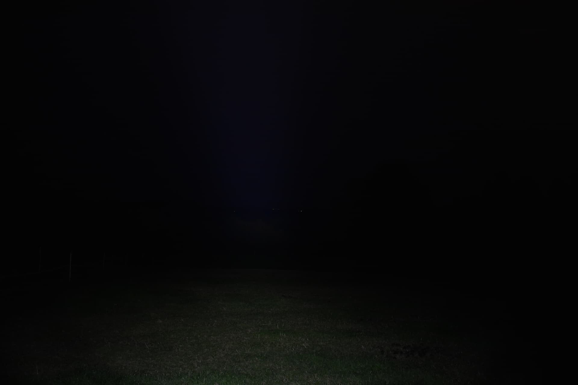
Sorry for the delay about taking beamshots, but the weather was awful with heavy rain and even snow and ice but finally got a clear night for it. All I can say is this thing performs amazing. Its very bright but also very directional and throwy. For this test, I set my camera on a tripod and locked the exposure using manual settings in order to show the difference between all the modes. This is the same field I used as last year. The distance is 125 meters to the trees, but can the flashlight light up the entire field?


Control (no light)
Low

Middle

High

Turbo
It certainly does look quite impressive in person and the beam and spill light up everything. My modified light could absolutely be used as a searchlight and if there was anything there you could see it straight away. However, this test felt too easy as the light could surely go quite a bit further than that. I moved to a different field. The tree is 250 meters away from me.


Here I have zoomed in as far as I can go on my 24-70 lens and cropped. Its very obvious that the light
is actually illuminating the tree.

Alright! That still seemed easy, let’s do one more and increase the distance again. The distance to the electricity wires is 550 meters. The distance to the trees and hedgerows is 600 meters. I had to switch out the camera’s lens to a 150-500 millimeters lens which can greatly magnify the image at long range.


The beam intensity is fading, but its clearly visible that the electricity wires mast is lit up. The trees directly behind are also illuminated but its much harder to make out. Realistically, this is the effective range where you can use this light to actually spot something. There isn’t much point doing another test because it will be hard to tell what is happening and you would not see anything without binoculars. I will calculate the beam intensity as well as soon as I get a chance using an android phone with a built in lux sensor.
In terms of lumens, I have no integrating sphere or way to accurately measure it, but using other flashlights with known outputs to compare with and guessing with the naked eye at short range, I would estimate that this light has 7000-8000 lumens. This even sounds about right considering the efficiency of the sft40 is 120 lumens/watt and the flashlight supplies 60 watts 60x120=7200. The sft 40 when supplied with 7A provides 2500 lumens and 3 of them = 7500 so that also sounds right.
Thanks to my upgrades, the flashlight can sustain a high level of output too. The sft-40 has almost double the number of lumens per watt as the Sbt90.2. This means that at lower modes there will be more light, less overheating and less energy dissipated (lost) from the battery when compared to the stock L7 sbt90.2. I also tested the light while going for a long night walk with my dog and was able to keep it on high mode for ages without stepping down, overheating or depleting the battery. I think the big metal part I installed plays a role in this too as it either absorbs or dissipates the heat or at least delay it from reaching the driver (which contains the temperature sensor). The flashlight did get a bit hot after extended use as expected but it wasn’t bad and still comfortable to hold.
That’s it for now, I am still open to any suggestions or feedback and there’s still plenty of time to change stuff before the challenge ends. Next update, I want to determine candela numbers and maybe do a test where I try to locate sheep from a distance as that was my goal.
Sorry for the delay now, but my flashlight was briefly unuseable due to the fact that my battery charger failed so that was a good excuse for me to get myself a xtar vc4plus to charge those huge 26650s. Anyways I conducted a test to find out how far this flashlight really goes by measuring the candela. I don’t have a lux meter or anything, but I do have an android phone with a built in light sensor, which I’m assuming is for adaptive brightness or some similar features. A nice feature when using service mode to get the raw sensor data is that we can see the CCT. Mine was close to the nice cool white 6500K of my LEDs.

In order to calculate candelas, the formula is distance^2 multiplied by the number of lux measured. The distance where the android phone was set up at was 10 meters. This means 10x10x2350 = 235,000 candelas.
To get throw distance in meters its the square root of the candela value multiplied by 4.
√(235,000x4)=969.5360 meters. This is a little bit short of my planned kilometer but I am still very happy with my result. Maybe my lux meter is inaccurate or something.
Bonus: flashlight comparison.
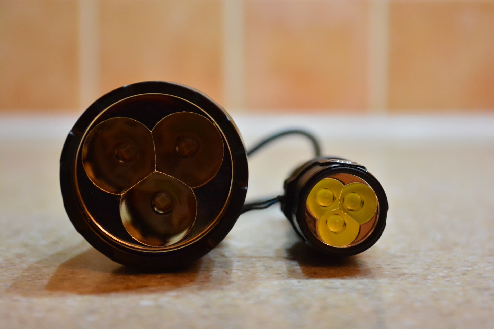
My light vs the only other triple I own which happens to be the Imalent ms03. You can see how colossal this thing really is as this was the biggest triple optic I could find online.

On the internet, people call the L7 a modern alternative to a D-cell maglite but I couldn’t find any photos of the two together. I have to admit these people are not wrong. They are virtually the same length. The difference is that the L7 has a narrower body and bigger head.

Here is a video of the flashlight operational. This was taken on a very foggy morning with light rain so the beam appears much more visible than it really is, however this does a great job showing the intensity of the beam and the modes.
**How good is the flashlight for its intended purpose (locating livestock)?

**
After some use, the flashlight and its searchlight-style beam pattern have proven highly effective at locating sheep that got separated from the herd or just checking in on them in general. Sorry for the shaky photo, but in person, the eye glow from the sheep makes them easily identifiable from far away because they are reflective. Also the color and size can make it easy to identify the type of animal present eg. fox. The effect is also visible in humans as you may have noticed in flash photography. I was tryying to think of a way to make my sheep more identifiable or reflective, perhaps using brightly coloured livestock marker paint on their coat, but after searching the web, it turns out reflective ear tags for sheep do exist.
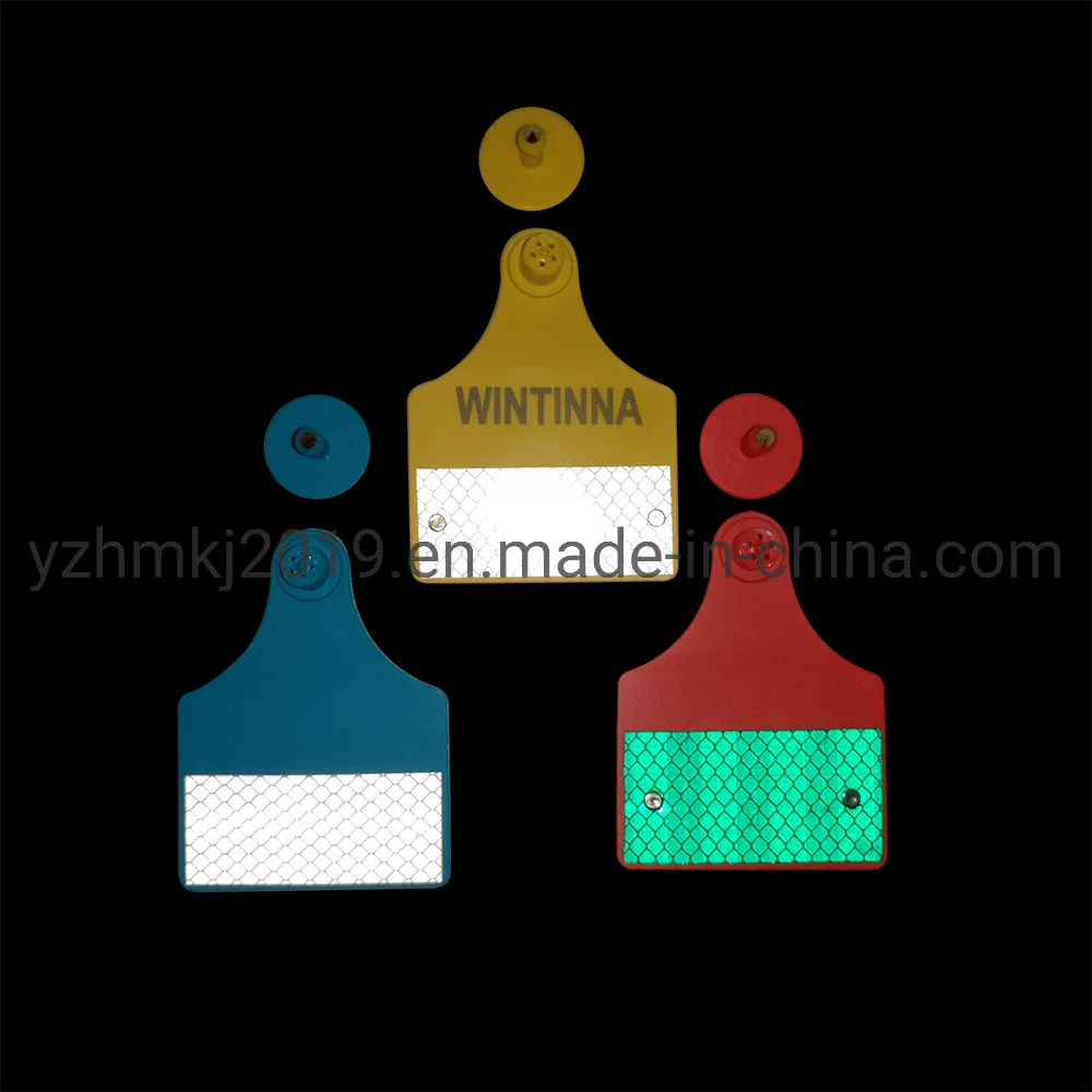
I might consider using these on the sheep, which are advertised for preventing the animal from being struck by a vehicle but they will be ideal for quickly finding the sheep using my new modified flashlight. Nobody around my area uses these so it will make it easier to separate my sheep from other people’s in case they break out and get mixed with another flock.
Final photo gallery of the finished flashlight


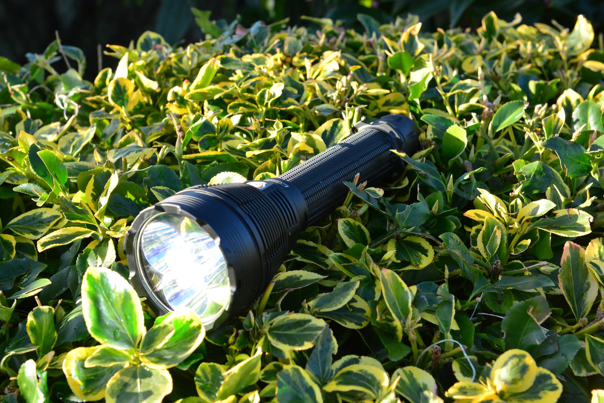
With that, my entry is concluded. I’m pretty happy with how it turned out. Good luck everyone and thanks for all the generous sponsors. I also wish everyone a happy holiday season and a happy new year.