Introduction
A month ago I received two prototypes of a new flashlight driver from led4power, named LD-2, with the request for testing them, especially the parasitic resistance. I was of course very honoured that I was to test his brand new driver (who am I to know it all about drivers? I don't), but I felt also a bit uncomfortable because testing them well involves the time and dedication more suited for someone retired with a lot of time on his/her hands than me: busy with work, family and being worried about lots of things, and in a constant state of sleep deprivation. Further, my electronics knowledge does not go much further than Ohm's law, even though in my experience in flashlight country you actually get a pretty long way with that simple equation :-) . I was somewhat relieved to hear that led4power also sent samples to HKJ, so wherever my skills stop, I'm sure he will fill that in brilliantly. Due to lack of time I almost stopped halfway, but in the end I found some time to at least gather enough numbers to do this post. So here are my findings, I did not do all the testing that led4power requested, but I also did a few extra things. I should present the numbers in nice charts. I may make them (it is quite labor intensive for me), but for time's sake I make do with the raw collected data, which I find quite readable, neat charts do not make the data that much informative IMO.
What is tested here?
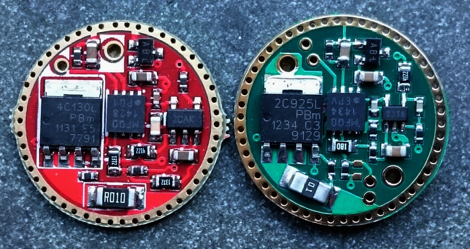
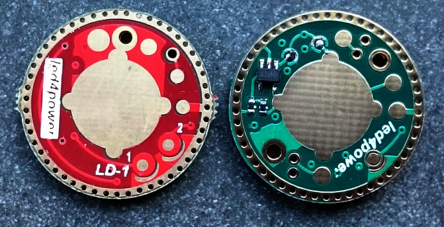
As the LD-1, the LD-2 is a 17mm diameter lineair flashlight driver made by BLF-member led4power, that is current-regulated at all modes (so no PWM) by controlling the current throughput of a FET. So any overvoltage not required for obtaining a desired current is burned off by the FET, which at times will dissipate a fair amount of heat. Compared to the LD-1, (at least) the following improvements have been made:
-the circuitry is completely redesigned.
-the driver is regulated at a user definable current in high mode by adjusting one resistor (was fixed at 5A in LD-1). The prototype boards were set at 6A, a triple can be set to even 12A if needed (the light and battery must be able to deliver that of course).
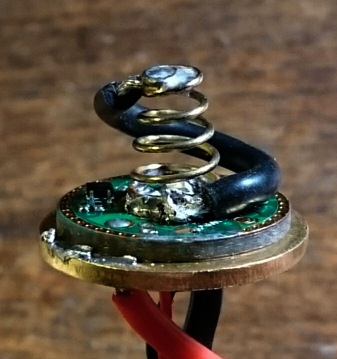
-parasitic resistance significantly lowered to almost BLF17DD level (parasitic resistance of a BLF-DD-driver is ~4.8mOhm, see post#17)
-has a user adjustable physically separate moon mode by choosing a suitable resistor in series of the led (not enabled on the prototype boards yet  )
)
-apart from a heat protection on the driver board, there is an option for a remote heat protection using a NTC-thermistor that can be glued to the pill or ledboard: an output stepdown is only happening when overtemperature is actually detected.
-the board has opposite through hole pads for the ledwires suitable for 20AWG wires.
-it has multicell support. One of the two prototype boards was set up for 2xli-ion use, able to drive 6V leds. The drain in sleep mode is mode is much lower than the usual 'zener modded' DD-drivers developed at BLF. The current of the prototype board was set to 6A which is a bit low for a MT-G2 or XHP70 (harsh on the FET with full batteries), but I tested it with them anyway :evil:
Measurements
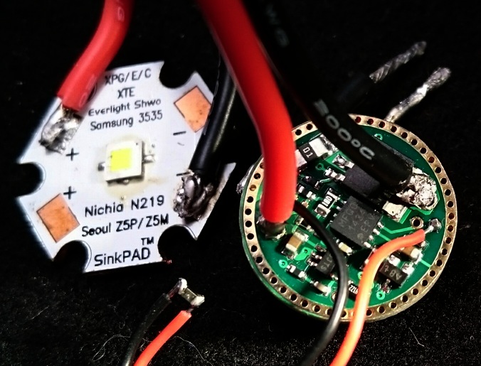
First I did the same measurements on the 1xli-ion prototype as I did on my test of the LD-1 nine months ago. The driver was connected to a power supply and in a bench set-up a dedomed XP-L V6 2A (dedomed just because that was at hand) on a DTP copper board on a cooled copper mount was driven at various set voltages as measured at the driver 'entrance', to simulate the various voltages that flashlight batteries may deliver to the driver. The current was directly measured at the 'battery side' of the driver and also by measuring the voltage over a 0.01Ohm sense resistor that was placed in between one of the led wires. Those currents should be the same of course, it was a bit of a waste measuring the current twice I admit :-( . I also measured the light output of the led, also a bit of a waste because I had measured the current/light output relation of this very led already before.
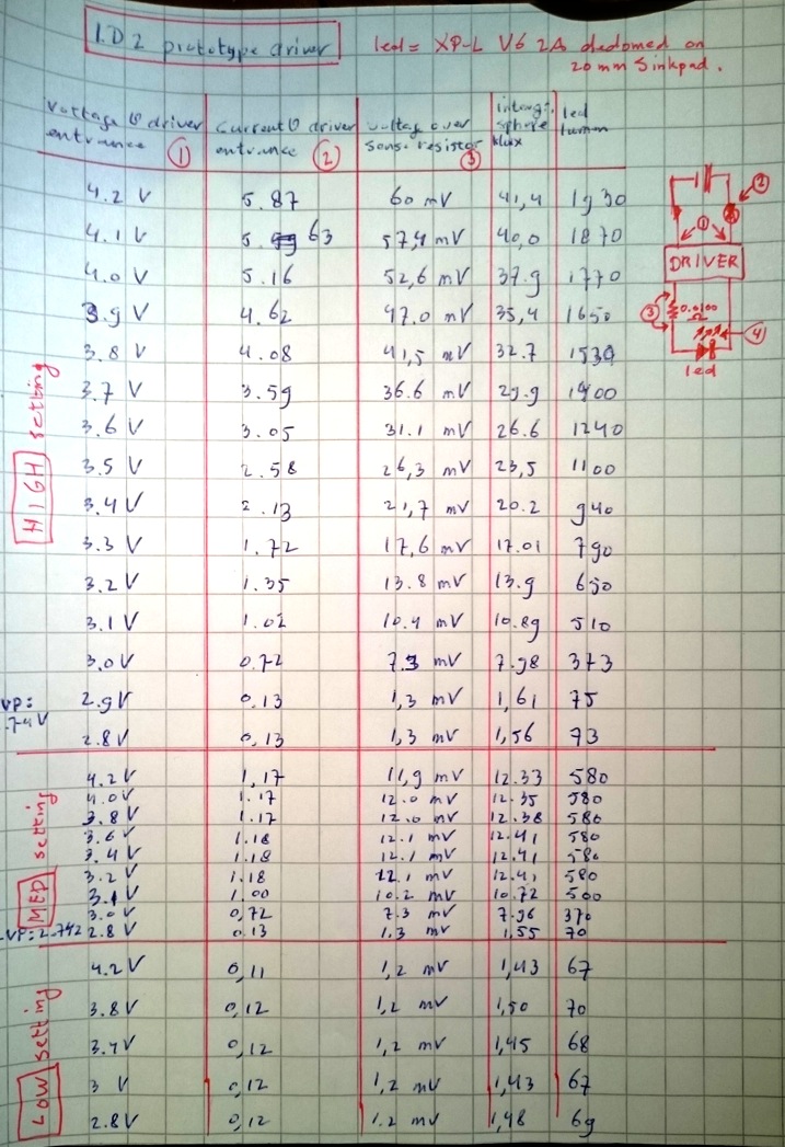
What can be seen here is:
*on the high setting, the driver nicely tries to regulate the current at 6A but only manages that above 4.1V which even the best high drain cell fully charged will not deliver at 6A. This is not caused by the driver, but by the relatively high voltage of the XP-L, direct drive on a single cell, 6A through a XP-L will not be reached. (to compare: below is a test with this driver with a XM-L2 that is in regulation at a lower voltage). Low voltage stepdown to low mode kicks in at 2.74V
*med setting is nicely regulated at 1.2A. Low voltage stepdown to low at 2.74V
*low setting is regulated at 120mA. Shutting down of the driver occurs at 2.74V (edit: not sure about the actual voltage, but it does shut down completely)
________________
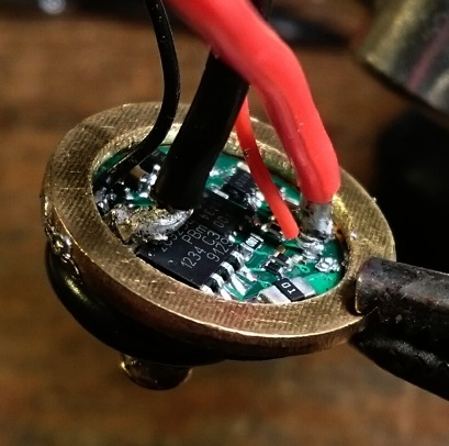
Being on a bit of a learning curve, for the rest of the measurements I skipped one of the current measurements and used the extra DMM to measure the resistance of the driver from battery-minus-in to FET-out (btw, the batt+ is directly connected to the led+ wire so no resistance in that path).
________________
To compare the parasitic resistance of the LD-2 to a 7135-regulated driver I had to make a 7135-driver of comparable output current. Unfortunately that is 16 7135 chips. Stacking-fun on a 105C ! :tired:
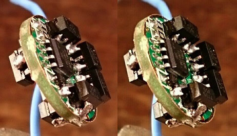 (stereo picture)
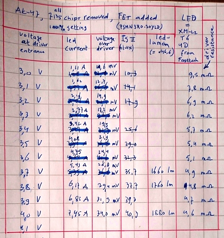
So just for the high setting, I again measured the LD-2 prototype driver on the XP-L, but now with driver resistance measured. Also I measured the same led with the same set-up, but with the 16x 7135 driver. Finally I measured the LD-2 prototype also with a XM-L2 (older batch)(to be fair to the driver: due to the lower voltage of the XM-L2 the regulation at 6A starts between 3.7 and 3.8V already). For all measurents, the entrance voltage of the driver was set, the other values were measured. The driver resistance was simply calculated by dividing the voltage over the driver by the current.
In blue the 16x7135driver measurements, in red the LD-2 on XP-L, in green the LD-2 on XM-L2, in pink the driver resistances for the blue and red test series. The driver resitance for the LD-2-XM-L2 series is not calculated, but is almost identical to the LD-2-XP-L series.
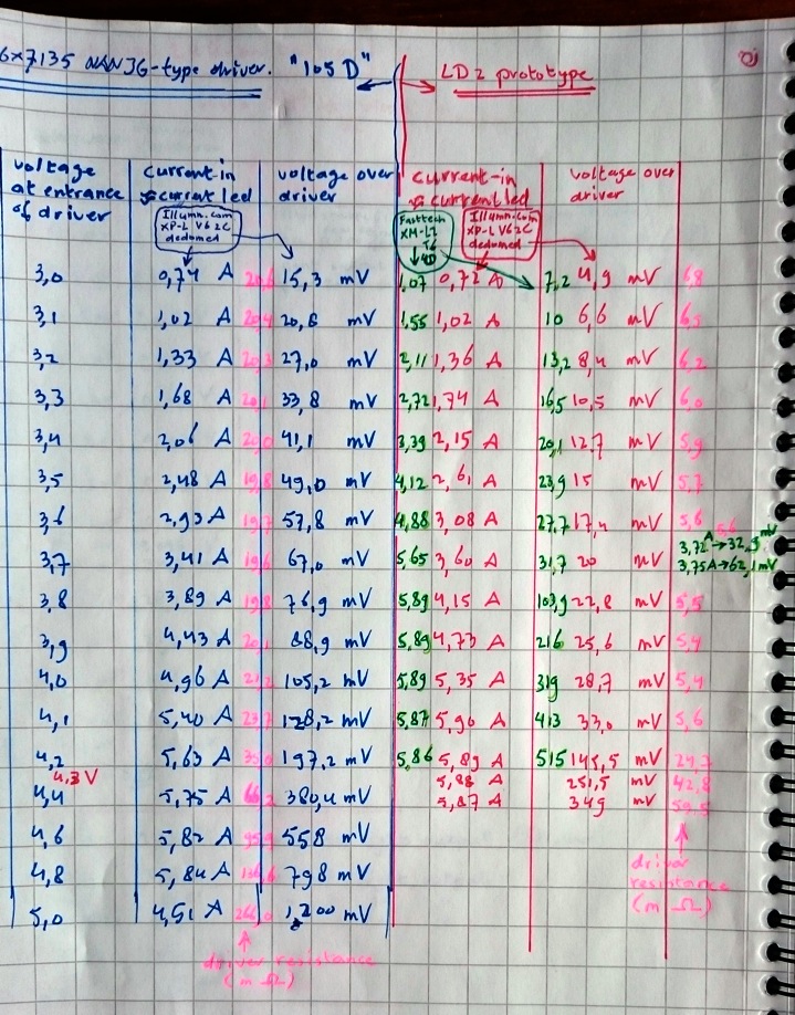
What can be seen is:
*In getting the 6A current out, the LD-2 performs a bit better as the 12x 7135, and that is due to a lower parasitic resistance: when the driver is out of regulation the resitance of the 7135-driver is around 20 mOhm, the LD-2 is around 6 mOhm. (for perspective: a steel spring is about 50 mOhm, a copper alloy spring about 15 mOhm, a proper Omten switch 4 mOhm)
*with the XP-L led no driver is able to regulate current at 6A on a single li-ion cell, but with a (older batch) XM-L2 regulation by the LD-2 starts at 3.7/3.8V, a high drain 18650 cell can actually deliver that for a few minutes (if no other voltage losses occur in the flashlight  ). BTW, this is not something that is specifically relevant for the LD-2 but for all single cell drivers, same for the BLF17DD driver.
______________________
I did a brief test to see if the remote temperature sensing worked. For that, as instructed, I glued a small thermistor (came with the prototype board) to the surface to be measured, in this case an old aluminium ledboard with an XM-L emitter, and connected that to the driver. I ran the driver on high setting on a 18650 IMR cell while pointing the led towards a luxmeter, and this is what happened:

Nicely, a stepdown to medium happened when the ledboard got too hot. Even further stepdown followed when even medium setting was too high (as this bare board has no heatsink whatsoever), then as the temperature went down again, the led output went up again. Well done! In an actual flashlight all this will be slower of course as there is actual heatsinking present then. But I'm quite impressed that this set-up actually saved the old XM-L led on a non-DTP aluminium board floating in air!
_________________________
Now on to the 2xli-ion board. This is a great new option in the LD-2. The delivered prototype was set at 6A, which is ok for say 2xXM-L2 in series, but low for a MT-G2 or XHP70 board, because on two fresh high drain cells, those leds in direct drive draw up to 9/10A, so if that has to be downregulated to 6A, i.e for the MT-G2 about 0.5V will have to be burned (at 6A) by the FET, that is 3W of heat for a component with no dedicated cooling!
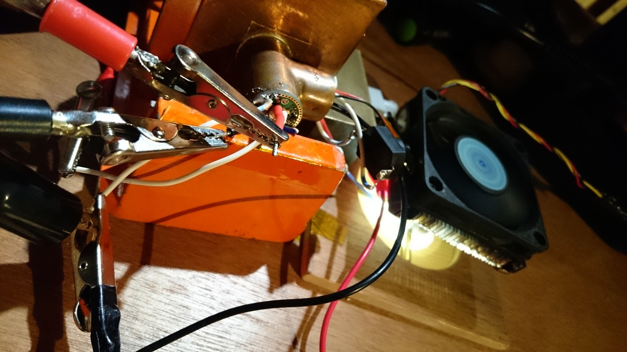
Nevertheless, I checked the board with a XHP70 led . Again with current measured between driver and led with a sense resistor. The switch is a forward clicky used as electronic switch for the driver:
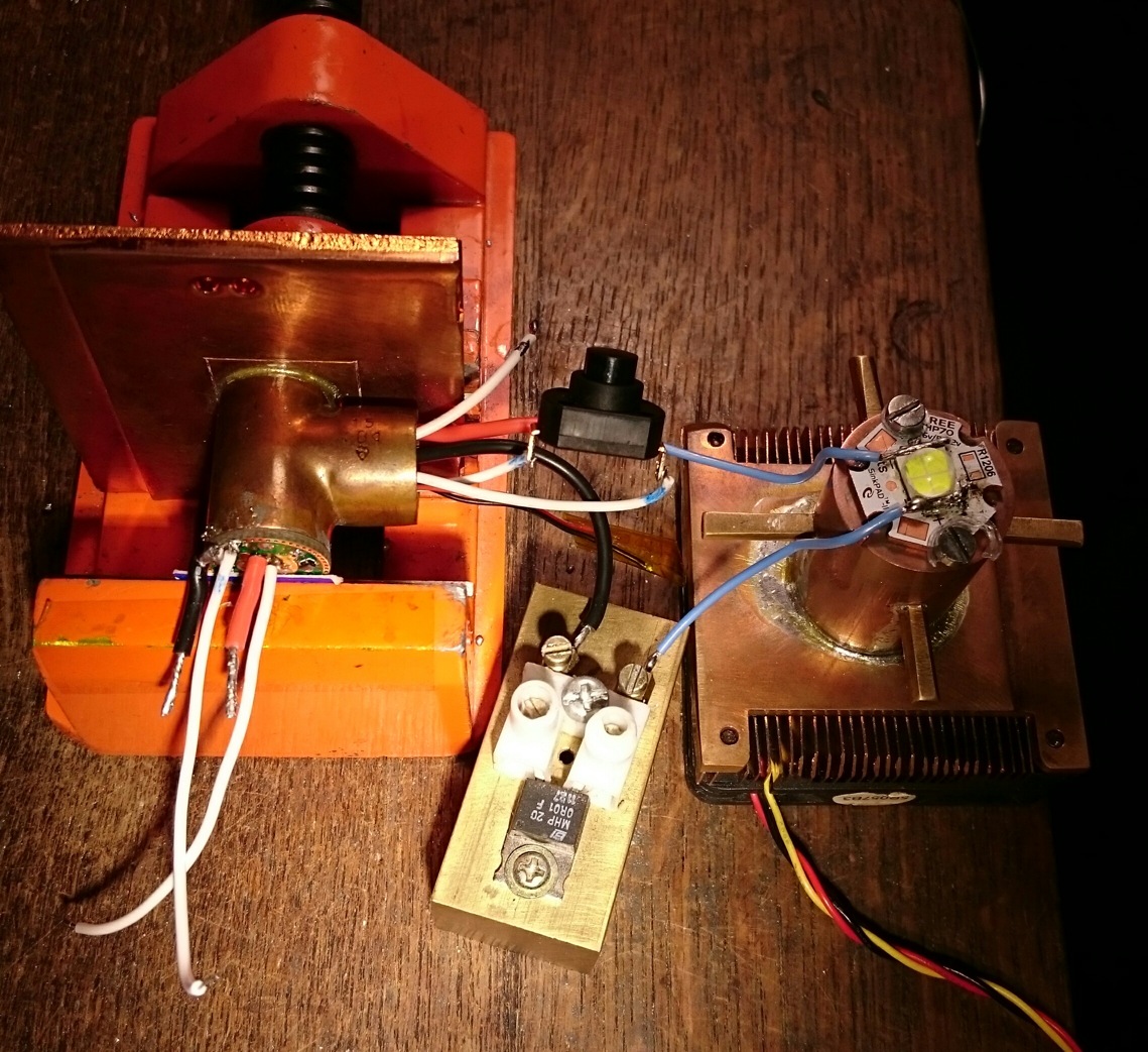
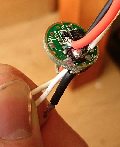
This is the test-mess, the wires on the bottom go to the power supply:

(left DMM measured voltage over the driver, top right DMM: voltage over the 0.01Ohm sense resistor (mV), bottom right DMM: voltage at entrance of driver. The led is under the fan, facing down into the integrating sphere.)
The results:
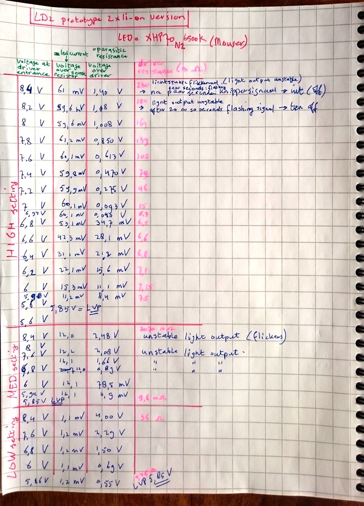
What can be seen:
*it works!!
*there are are several remarks written down of unstable flickering light output/FET voltage in this test at moments when the FET had to burn relatively much power. Of course voltages above 7.8V are unlikely to happen in a flashlight situation, but it also occurred in medium modes, in which case the 8+ Volt is very likely. After consulting led4power, he asked me to check if this also happened on two 18650 batteries in series as power source. I checked that with two Sony VTC4 high drain batteries, and the flickering did not occur in any mode. Then I tried to reproduce the flickering behaviour again with the power supply, and it did not happen again, also not in the flashlight mod that I have done later with this driver (see reply #1). Led4power thinks it is something coming from my power supply or from the switch or what, but not from the driver. I do not think it is likely that my power supply is the source of the trouble because as far as I know, it is a straightforward good quality lineair power supply (not a switch-mode one)(EA-PS 3016-20 B), but it could have been the switch not making good contact, or something else, I don't know.
*the driver shuts off when the temperature (measured somewhere on the board) gets too high. It only happened on high setting above 8V, a situation not likely in a flashlight. But in the bench set-up, the driver is not also receiving the heat from the led, so who knows what happens inside a flashlight...
*the parasitic resitance (driver resistance when the driver is out of regulation) of the 2xli-ion version is comparable to the 1xli-ion version, around 6.5 mOhm.
*low voltage step-down and eventual shut-off occurs at 5.85V, which is quite perfect for a 2xli-ion setup.
___________________________
Conclusion
A weak point inherent to this type of driver is the amount of heat produced by the FET in certain situations (not always, the driver gets away with it most of the time, and there are heatsink solutions for the FET thinkable). That said, the LD-2 has a whole load of improvements and extra features compared to the LD-1, and in these tests they seem to work. From what I can measure, I think this is a great successor to the LD-1, and one of the best flashlight drivers around!
My own conclusion: driver testing is more challenging for me than I like, and not completely my cup of tea. But I must admit that I have said that about emitter testing earlier.. 
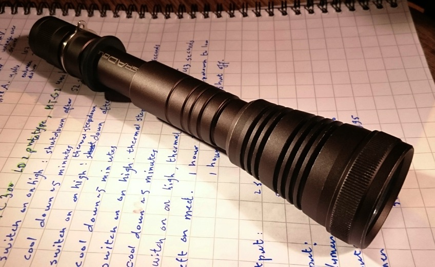
In the next post will be the build and observations of a mod that I did of my Shadow TC300 flashlight, using the 2xli-ion LD-2 prototype and a 4000K MT-G2 led. It works together nicely! When time allows I will do the post, I hope within a few days.
EDIT May 11th, 2015: I measured the parasitic resistance of a direct drive FET-driver as well, in post#17