
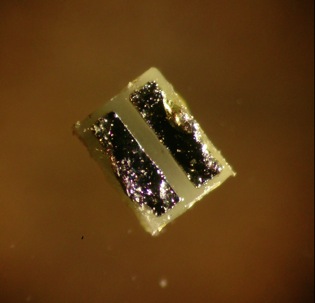
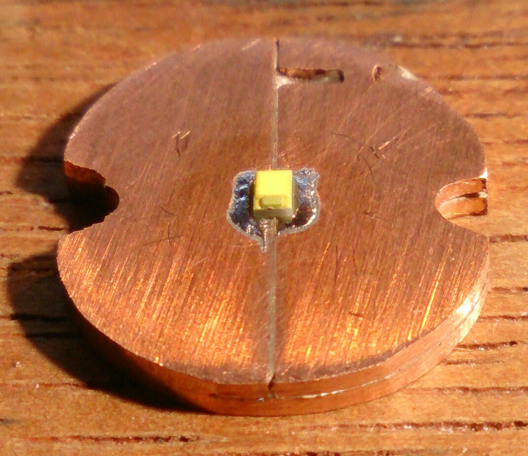
 (pictures taken after tests, some flux and solder remains can be seen)
Part of a recent (for my budget) epic bare leds order at Mouser were two LuxeonZ emitters, although I knew I did not have a proper board to mount them. It is a led without dome with the same die-size as the LuxeonQ and XP-E2. Apart from being dome-less, a difference is that the complete led is not much bigger than the die, and the thermal resistance should be a tad better than the LuxeonQ:
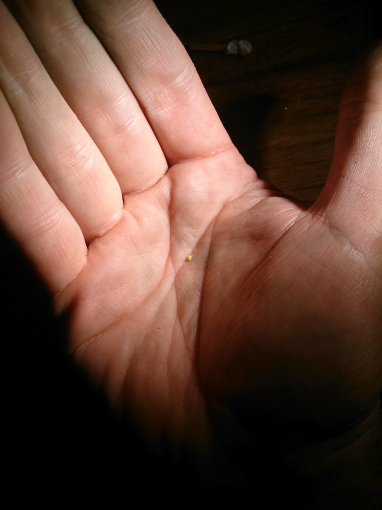
I wanted to test them, so first thing was to make a board. I started with a piece of 1mm copper sheet:
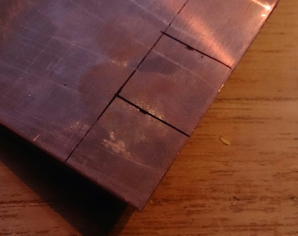
Two square 16x16mm pieces were cut and sanded flat:
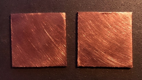
one piece was sawn in half, one of the halves was soldered on the other square (using a small butane torch), using solder paste, the other piece was sawn in on one side to ease the soldering of a wire (but I did not use that in the end, did not work):
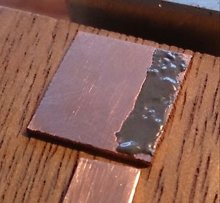 after soldering:
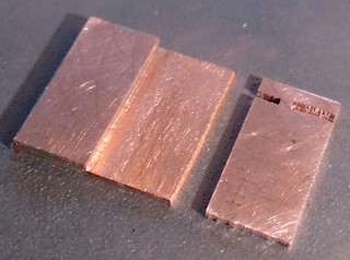
The other piece was now glued in place with Arctic Alumina Thermal Adhesive, and the top was sanded flat afterwards. I looked up what temperature this adhesive could handle and it said more than 150degC , so I hoped that it would withstand reflow temperature.
Resistance test: the two sides were nicely insulated from each other. I should mention now that if I would make such a board again, before glueing, I would have already sanded the board round and make the necessary cut-outs, so that the sanding of the side of the board was completely done. More about that later.
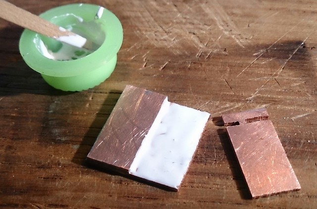
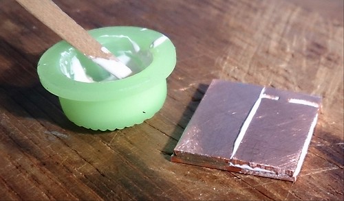
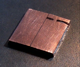
Now the board was sanded round and two cut-out were made. here my relative inexperience with pure copper showed (should have been warned by the lathe folks here at BLF): copper behaves like a paste when sanded, so it smeared across the insulating adhesive layer, causing the + and - to short at numerous places. It took me two hours of carefully scraping the side of the board with a scalpel to remove all the shorts (scraping, resitance testing, scraping, resistance testing, etc. until finally: victory!).
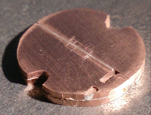
Some solder paste was applied and the led placed, taking care that the led-minus was connected to the core of the board (no electrically neutral thermal pads here!). then the led was soldered on my (rebuild solder iron) hotplate. It was nice to see that at the soldered side the solder melted a bit earlier than at the glued side (direct confirmation that -with these ticknesses- solder conducts heat better than Arctic Adhesive :-) ).
Another mistake: I should have soldered the led wires with the same reflow, there is no way I could get the wires soldered without heating up the entire board again. So I placed the board on a piece of aluminium, taped the wires in place with some Kapton tape (magic stuff for a thousand things!), blobs of solder paste applied, and back on the hotplate:
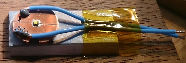
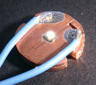
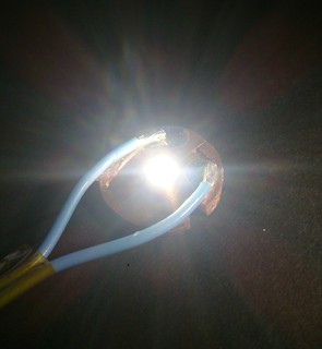
And voila, the led even lights up with the led-tester at 1mA :-) , and at 50mA . Some glamour shots in stereo:
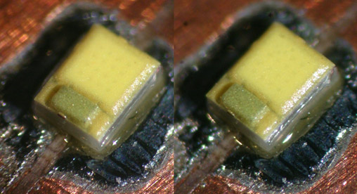
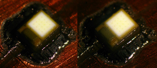
It is time for some tests....
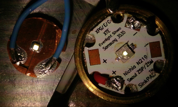
The first disappointment: when viewed next to a dedomed XP-E2 the light emitting area is clearly bigger than that of the XP-E2. If the die size is indeed the same (1x1mm), apparently the phosfors are less tightly applied over the die. This spoils directly quite some throw potential :-( , the led must perform quite a bit better than the XP-E2 to compensate for this. (and throw is what a flashaholic wants from such a small led, otherwise you take an XM-L and have way better output and efficiency).
Time for the test-set-up (for details of the set-up, see my other led-tests, in short: ledboard on block of alu, led directly to power supply, reflector on top and ceiling bounce lux was recorded and calculated into OTF of reflector lumens, by comparison with reference flashlights. Everything not too accurate, but probably the values are not way off from reality.)
So this is what I got, in the graph the LuxeonZ can be compared to the LuxeonQ and the XP-E2 that I tested recently exactly the same way (well, actually nicely mounted on Sinkpads instead of on this makeshift board):
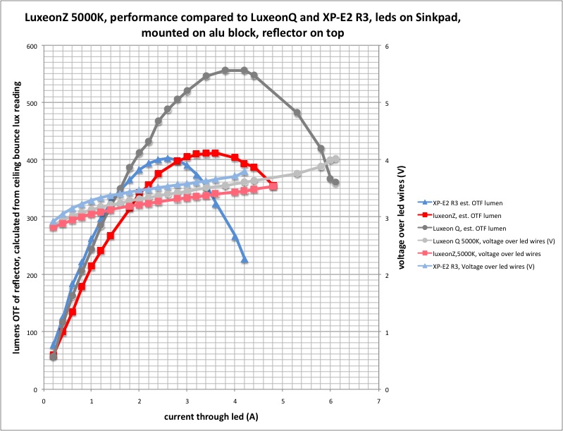
I am not satisfied with the LuxeonZ. it does outperform the XP-E2 by quite a bit (mind that the XP-E2 from the test was not dedomed, if dedomed the output would be, say, 20% or so less), but surely not enough to compensate for the bigger light emitting area (which is somewhere in between XPE andXPG). Actually, in die-size and output this LuxeonZ behaves quite like the sliced down LuxeonQ that I tested earlier (I measured the OTF output of the cut-down LuxeonQ in a C8 flashlight, see in my LuxeonQ-thread).
The only really nice thing about the LuxeonZ is the low voltage, on average more than 0.2V lower than the XP-E2 at a given current. so the efficiency is a bit better than it looks like in the graph, and good for a led without dome.
One other thing, for what it is worth, these Luxeon dies are less sensitive to the high currents that go above the maxumum output than the Cree leds of the same die-size (=XP-E), the die looses less output when current goes up and can survive higher currents.
I am not sure how much influence the use of this DIY copper board has on the results, compared to a Sinkpad. So to make my life easy, I just assume that the heatsinking properties are just the same  .
.
I should have done a 'real life' test in a C8 or Uniquefire UF-T20, but at this point I was quite sure that it would perform as mediocre as the (sliced down) LuxeonQ, so I called this test a day.
I did have one LuxeonZ leftover however, so the board went back on the hotplate and it got new wires and a new led:

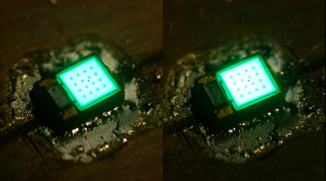
I could not resist it when ordering at Mouser: a luxeonZ-cyan (490-505nm). I love that colour!  . On to a quick alu-block test:
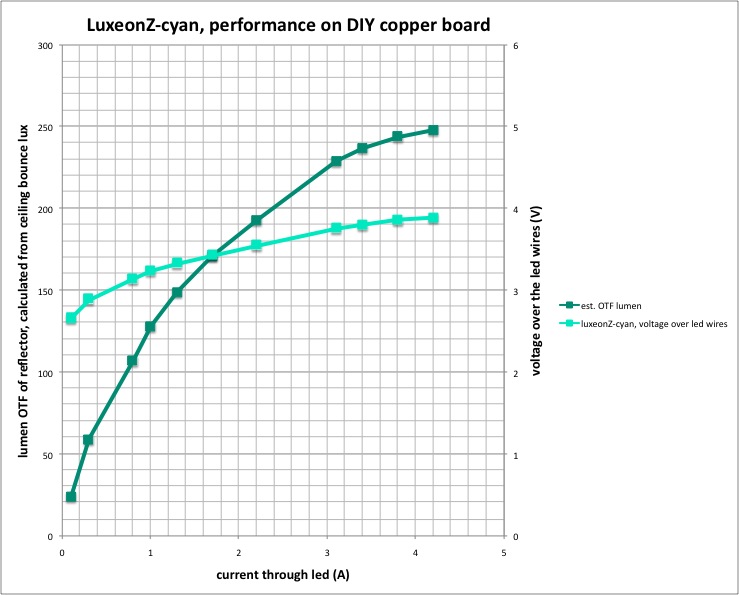
Joehoe! this is nice for showing off in a small EDC light:
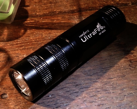
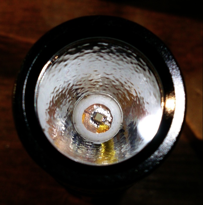
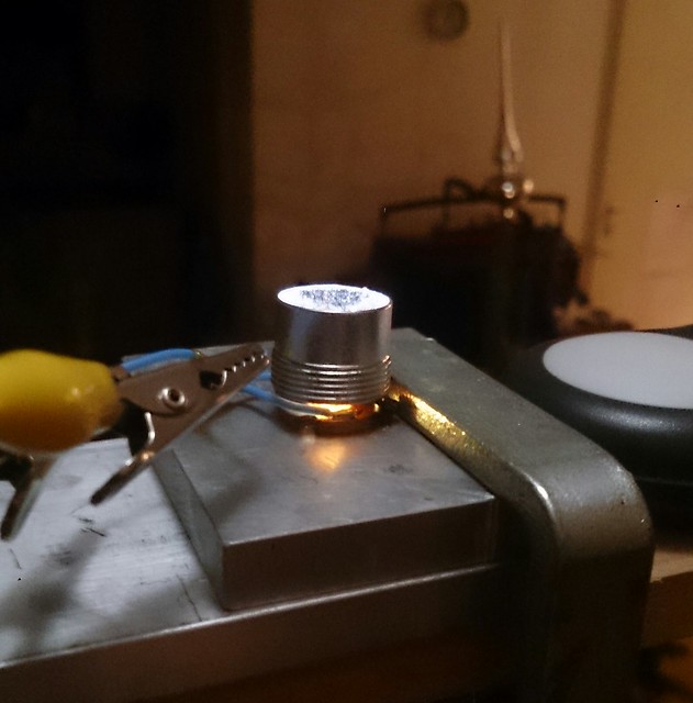
It actually was a pain to get the led-board in the light, there are no centering rings for a LuxeonZ, and the reflector is pressed onto the board in this type of light when the pill is screwed in, too much pressure and my not too reliable DIY board shorted through the (bit too thin and roughly sanded at the side) Arctic Adhesive layer. Next time I make a board like this, the side sanding is done before the glueing, and the layer of AA-adhesive will be just a bit thicker, so the board will be much more reliable. But I got it done, put an old 105C-driver in it that had 5x7135's left on it, but because the led-minus is directly connected to the body, the driver does not do much and it has no modes (I guess the led is just direct drive), I measured 2.45A on a freshly charged Nitecore 16340 battery and 183 OTF lumens (for what lux-readings are worth with close to monochromatic 500nm light) and was delighted with the result:
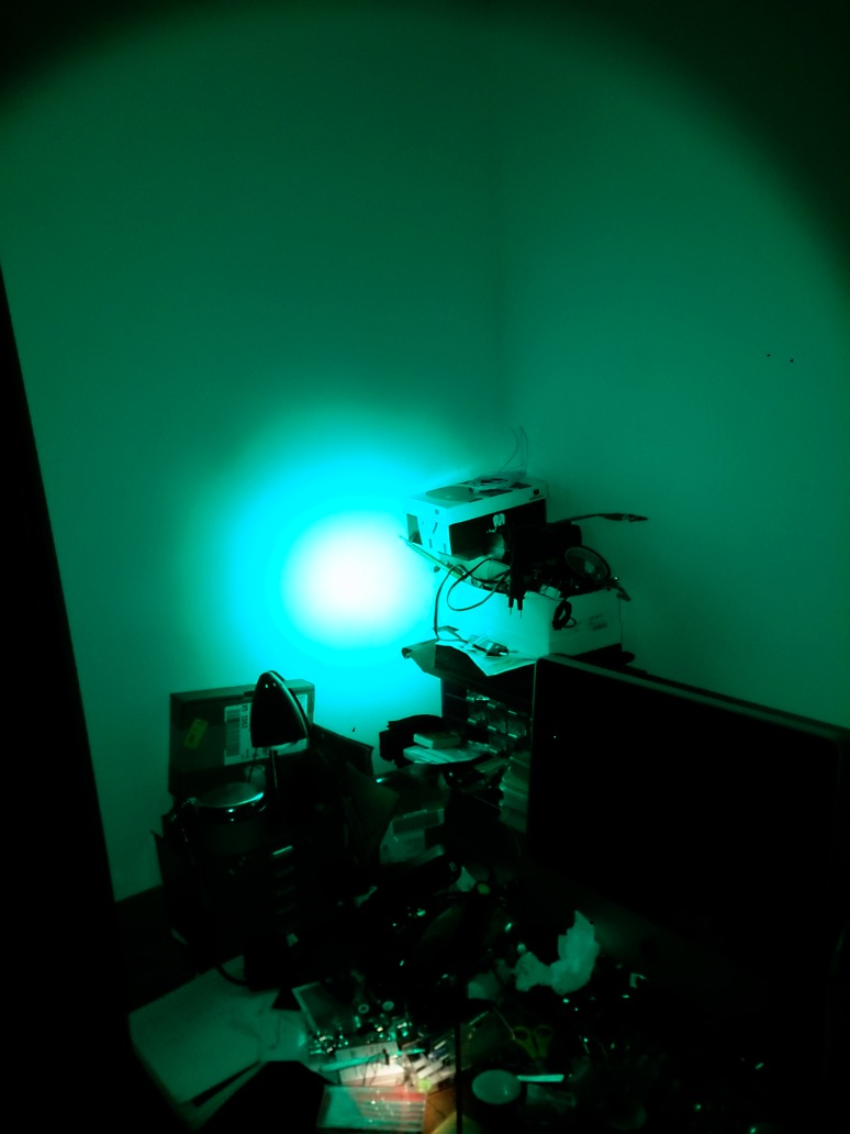
The picture does not do justice to the wonderful light this flashlight produces, and because of the small die it is quite throwy. I have even carried this light as my EDC for a week now, made me smile with every switch-on, and discovered how still usefull a light is with zero CRI  .
.
Thanks for reading!
 .
.


