Take a look here Ouchyfoot made a deep red Luxeon rebel triple :
Thanks, khas, I know (and admire) ouchyfoot’s work there.
The soldering and wire-cramming into that Sinkpad and extra board to make it work parallel is at the edge of what I can handle,
RMM has said the Sinkpad2 traces are much poorer than the Noctigon’s traces earlier in this thread
That’s why I asked if Noctigon makes a triple that would accept Rebel emitters (their boards are much easier to make work parallel)
I don’t know the footprint of the various emitters.
I did learn that the color XP-E2 emitters are available now and that may be the way to go.
I just haven’t found a lot of info about what Noctigon makes; do they have a home website?
Here: http://intl-outdoor.com/components-mcpcb-c-57_114.html. Hank (IOS) makes them - Noctigon is his brand.
There aren’t any noctigon boards with a Luxeon rebel footprint though, if that’s what your looking for.
That was my hope. Next option will be three different color XP-E2s. Figuring it out. Thanks
Well, if you can get enough interest up from others (or willing to buy large yourself), maybe Sundy can help you out with a custom job here.
The 20 mm noctogons are set up for either parallel or series depending on which jumpers are used
I’ve just tried asking Cutter if they can make a triple parallel rebel board, looks feasible.
Lacking an electronic switch board, what I will have to do is to denude the old board and use it as a connection board and to hold the switch, then file the driver to a snug fit and slide it into the pill with heat sink compound. I might even add some metal around the edges to increase contact area.
I also thought of filling the pill with liquid, but this is too expensive a light to experiment with.
Just add it in the notes for Richard to build for you, I have had several 4S 2.5/ 3.0 amp E-switch Mtn MAX Buck drivers built for me by Richard for my XHP35 SD75 and T90-2 builds. 
I built a MTN 17 FET+7135 with bistro yesterday.
I thought I did a pretty good job, but when I installed it, all I got was low. Not moonlight, just low. It doesn’t matter what I do, it won’t go into programming mode or anything else. I don’t know what’s wrong, or where to start trouble shooting.
Any suggestions?

I don’t think it’s a hardware issue from what i see …
I built a bunch of these with ATtiny85's, higher value voltage dividers, and the SIR800DP and not a problem with any of them. Seems like maybe the OTC?
I’m way over my head Tom. I can build them, it’s just following a blueprint, but the DNA of these things is beyond me. I might heating it up again and wiggling things around a bit, but other than that…? I have no idea what the OTC does. I could replace it, but have no idea why it wouldn’t perform correctly.
I reheated the board and shifted things a bit to make absolutely certain everything was flowed down fine and replaced the 1uF capacitor. Some thing, one low mode.
I’d sure like to figure this out, because if I’m the problem, I don’t want to build ten more boards and have the same results.
Your board looks pretty good. Make sure the zener diode is not backwards. You can even remove it for a test - I run one of these in a triple 219C without a zener, no issues.
I have the zeners facing exactly the same as the pictures on Richard site. I’ve built lots of other MTN FET drivers, but this was my first +7135 board so I carefully built it one component at a time using a jewelers loupe to make sure I had everything configured correctly.
Z1 was the only suspect on your photo since it had no markings showing. It is probably just the lighting though.
For the rest your board looks good.
Ouchy - have you done full continuity checks? Be sure where you should have connections, then check for shorts? I do that with every board I build and have found problems - even with a couple of these boards, but all were obvious shorts that were easily fixed with the iron. Yours has nothing obvious from the pic, but agree with DEL - can't see the labeling on the zener, so who knows - but sounds like you got that right too (with the "W7" label, the W should be towards the C1 cap).
This is a view of mine:
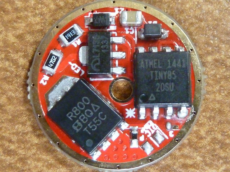
Was the MCU pre-programmed with Bistro from MtnE? Richard and Lisa don't make mistakes often but it has happened - maybe it's not programmed?
Thanks for the pic Tom. They sure come in handy for reference.
Yes, I have the zener mounted with the line towards the large capacitor.
The problem with me checking with a DMM is that I really don’t have any idea how these components relate to each other, so I don’t know what’s right or wrong.
What would happen if the MCU had no program flashed in it?