Hello,
I have talked about this project before, mainly in my ebastlers electronics corner, but I feel like it has been clogging up what was supposed to be a fun thread about small random projects too much, so I moved it into it’s own thread as a central place for information and updates about this project.
Introduction
What is the S21Evo Boost? It is a powerful and feature-rich open hardware driver to replace the rather limited drivers in Convoys S21E hosts. I really like the S21E for a variety of reasons (looks, price, emitter choice, ability to use with both TIR and reflector, small dimensions for a 21700 light, USB charging…), but I am not the biggest fan of Convoys e-switch drivers. While they work well (The MP3231 in their boost drivers is really good) the UI is a bit lackluster. No way to get from moonlight to the regular modes, strange ramping speed, 10c for lockout, no aux… If you are spoiled by Anduril lights, they are not great.
I am a hardware developer in my dayjob, so I figured I should just solve these issues myself instead of waiting for someone else to fix them for me and started working on my own replacement driver for the S21E (for now, boost only. Buck might follow). And since I tend to get lost in feature creep, that was exactly what I did. More about that in the next chapter ![]()
Feature overview
The driver focuses heavily around making full use of the USB port. Apart from that it also is a rather efficient boost driver, but not expected to be significantly more so than Convoy’s default Boost drivers. The most important features* are listed below:
- Firmware updates over USB - say goodbye to dedicated flashing dongles. Will work from Windows, MacOS and Linux (or any other platform that supports drivers for STM32 USB DFU).
- Up to 5V 3A USB charging
- Up to 5V 3A USB powerbank functionality
- 30W Boost converter (most likely too much heat for the host, but might be nice as a short turbo)
- Very low resistance reverse polarity protection FET and oversized inductor for high efficiency
- HDR capability (2 shunts with n-ch FET)
- User settable charge termination voltage
- User settable max charging current
- User settable powerbank behavior (prefer source/prefer sink/sink only/how deep the battery is supposed to discharge…)
- Setup of all parameters via USB. Most likely a web-app, similar to something like VIA/vial/remap-keys for custom computer keyboards
*Note: Many of these features will need extensive software effort to work, so they might take a while to be included. This list contains the hardware capabilities, not the actual software capabilities (for now).
Technical information
MCU
For the implementation of my planned USB features I needed an MCU that was small enough to fit on the very tight PCB, offers USB (including USB capable bootloader from the factory) and has sufficient flash/RAM for the live remapping feature. It should also not be BGA/WLSCP since the microvias/buried vias needed to contact those add a fortune to the PCBs in small and medium batch sizes.
There is exactly 3 MCUs on the market which I am aware of that fit this niche, the AVR32DU family (very new, not sure if they actually ship with a USB bootloader), the STM32F041 family (very limited in RAM and flash) and the STM32C071 family (very new). I ended up opting for the C071 (to be precise, STM32C071GBU6), due to it having the largest RAM/flash and guaranteed USB bootloader capability.
What they all have in common is, sadly, the lack of a DAC. Therefore the LED current must be controlled via filtered PWM in all three cases. In theory, with a sufficiently low low pass frequency and sufficiently high PWM frequency, this should have zero visible jitter/flicker, as the feedback loop sees a smooth DC signal. How well it works in practice (how much dynamic range I can get out of it) remains to be seen. It also means I need an additional capacitor and resistor, and that was, as you will see, a challenge to fit. But it was the best compromise I could find.
The STM is a 3V class MCU, which is why I am running it at 2.8V via a small LDO - this way the MCU voltage will not fluctuate from a full to an empty battery. 2.8V is outside the USB2.0 FS specs for the MCU, but according to ST it seems like it will still work, just slightly out of nominal specs.
LED driver
The LED driver is a MP3432 - very similar to the MP3431 used in the Convoy boost drivers, and the same chip used, among others, in the D3AA. It is highly integrated and very efficient. My schematic is based a lot on the valuable feedback and help @thefreeman offered me (huge thanks at this point for everything!), so I hope it will work well.
I opted for a 5mOhm and a 1 Ohm shunt, and a n-ch FET of approx. 2mOhm (so ~7 mOhm total shunt resistance for the high current shunt). A larger value high current shunt would allow for lower min current (and therefore a larger low current shunt, and higher overall dynamic range), but it would also mean higher losses. I do not have the experience to predict if I made the right tradeoffs for this particular application, but a simple resistor change is no big deal and something I can experiment with on the first batch drivers if needed.
Charging/Powerbank
The charging part of this light is handled by a MP2722. This chip can both charge with up to 15W and be used as a 15W powerbank. It features fully integrated, USB spec compliant Type-C battery charging negotiations, and can be controlled via i2c from the MCU. On this chip you can set up almost everything. Whether it should be “sink only” (flashlight charging only, no powerbank), source only (only powerbank), “prefer sink” (if connected to a notebook or phone, the flashlight will prefer being charged by them), “prefer source” (opposite of before, and it will only charge when connected to a pure charging port) etc. You can set charge termination voltage and charging current, powerbank current, and many other things.
This chip will be the heart of the battery management on this light, together with (ofc) a beefy low Rds_on MOSFET for reverse polarity protection, ensuring the light is not affected by a wrongly inserted battery.
Due to space constraints I had to use a rather small inductor for this chip, which (while current wise within specs) is slightly outside of the recommended internal resistance range. This will affect efficiency, but I think it should still be acceptable - and I preferred having the higher efficiency for the main LED boost which is, after all, the primary function of this light.
E-Switch / AUX
Due to technical reasons, this driver needs both the e-switch and the aux logic inverted compared to Anduril lights. The e-switch needs to pull the MCU pin to Vdd as this is the method to enter the bootloader when held at powerup. Usually, e-switches connect the MCU pin to GND. Since my MCU runs at 2.8V, it would not have the forward voltage to light up green and blue LEDs reliably. Therefore the AUX LEDs are connected with their Anode directly to the battery voltage, and with the cathode (through resistors) to the GPIOs in open drain mode.
Since the MCU has all inputs 5V tolerant, both the e-switch and the AUX LEDs can connect to up to 5V without damaging the chip, even if it is running at only 2.8V.
The e-switch PCB has 4 RGB LEDs for a more uniform lighting than the default Convoy e-switch, and more wires (since it is RGB, as opposed to being RG only). Size-wise it is, obviously, compatible and can fit the host just the same.
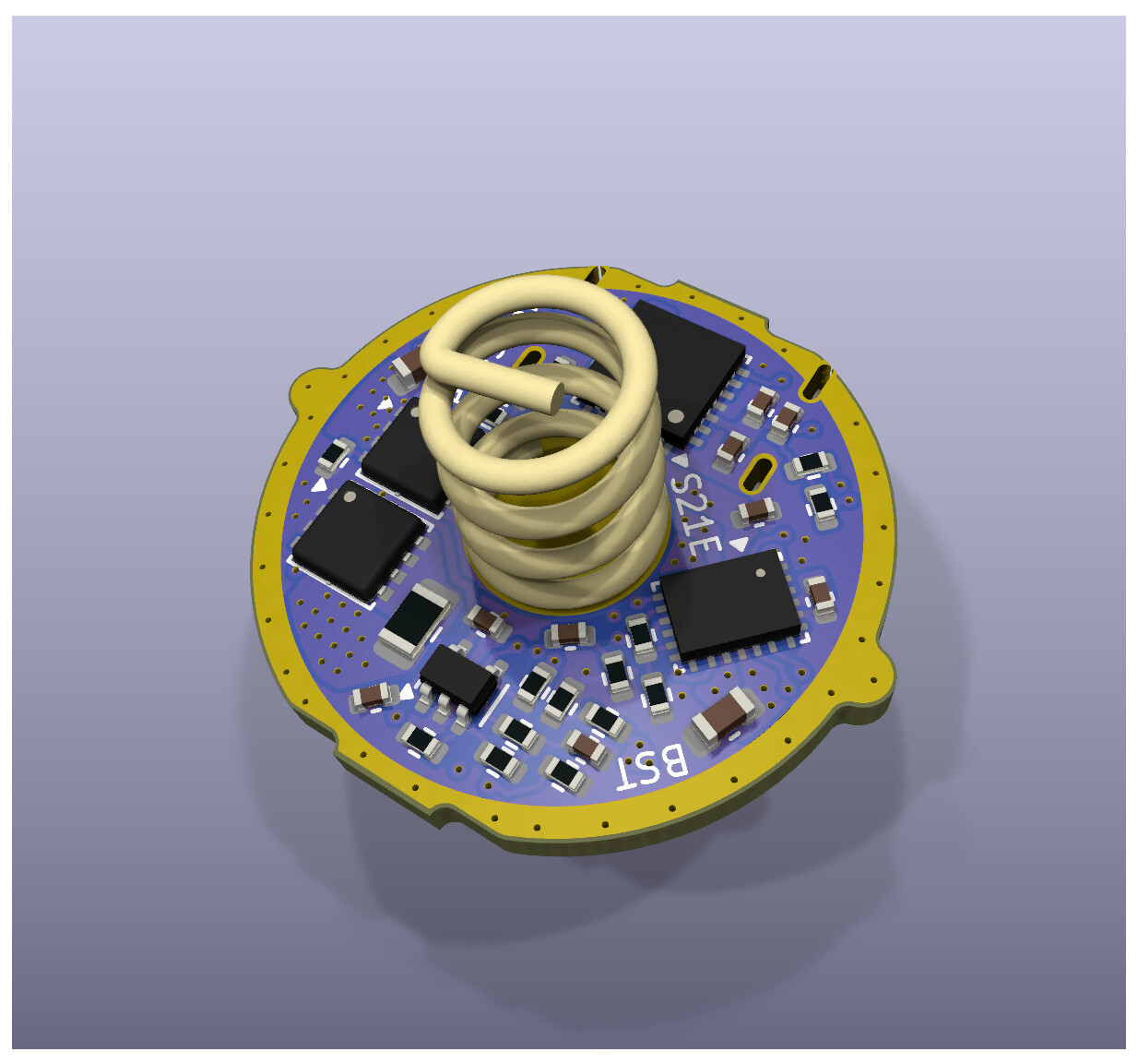
Renders, main driver


Renders, button PCB


2D views, main driver


Yup, the MCU is a little close for comfort to the spring pad… Everything is, tbh. Should be fine, but I will try to squeeze it a little bit further up if possible. Will be tight with the retention ring. The whole PCB ended up being incredibly tight. Every space that is not occupied by components or pads, is filled with vias… The aux/button pads will be a pain to solder, but making them any larger was not possible. I really wish Simon made the driver for this light 1-2mm larger… The host would have the space for that.
Software and UI
This is where things get complicated. As many of you know, Anduril only works on a couple of Atmel chips, and does not support most of the features I am aiming at with this light. While I have heard of some community plans to port it to other chips, I decided that a driver that so clearly breaks off from community standards should also get a clean slate software wise - built around and optimized for the hardware capabilities.
I want to streamline and simplify the UI - many features you know (and maybe love) from Anduril may not be included. Others will be added. This driver is mainly a passion project of mine, and as such reflects primarily my own needs and preferences. The software is still the biggest WIP by far, and therefore this is just a rough sketch below that might change.
My basic UI is supposed to closely mirror the Anduril simple mode. It is proven, it is intuitive, it just works. Don’t fix what’s not broken. The UI is supposed to be very simple. Moonlight, a couple of modes (user selectable number & brightness), ramping mode (user settable floor/ceiling/speed), turbo mode, battcheck, lockout. I personally do not need any blinkies and specialty modes apart from battery check, so I am not planning to include any of those, at least not for the beginning. Maybe once everything else is settled.
RGB AUX will be used during charging, for battcheck (user configurable whether the light should use the emitter or the AUX LEDs), and as an optional indicator color when off (same behavior as Anduril for the most part).
The only addition to the basic UI will be a (hard to accidentally push) toggle to switch between sink only, source only and prefer source mode of the flashlight. Prefer source should work with almost every power supply and phone, but some devices have wonky USB-C implementations and might act up. Having a way to force those into the desired mode of operation can come in handy.
Flashing
Flashing will work using the STM DFU bootloader. This mode is entered by holding the e-switch down while the MCU boots (either by tightening the tailcap while holding the button, or by removing the battery and plugging it in while holding the button). Flashing new firmwares in DFU mode is mainly done through the ST dfu-util command line application, or one of the many existing GUI implementations. I will not reinvent the wheel there and use what others made. Since I already have it for custom computer keyboards, my own pick is “QMK Toolbox”.
Setup
I’ll be honest, I am too dumb to remember set up patterns and click codes, and even with a diagram in front of me I still struggle with many options. That’s why I decided to take a step sideways, and instead of setting the light on the light, I will allow changing all settings via a computer. This is still only a rough concept, and I have not yet decided how the communication is exactly supposed to work, but the rough idea is that i would like to offer both a simple command line tool (for Linux) and a web-app (for webUSB enabled browsers) to change parameters, which the flashlight then stores internally. This will be the very last thing I will turn my attention to, after everything else is ready and working, so don’t expect anything more substantial within the next couple months.
The idea itself was inspired by VIA for mechanical keyboards, a software which allows the user to not only remap all keys, but also change things like the RGB illumination and others through a web UI (see the example picture below).

This part of the firmware is very intimidating to me, but I will decide how to tackle it (and if I should ask for help) when the time comes. For now I am approaching this topic step-by-step.
Roadmap
This roadmap of the design is much more detailed than it would have to be, as I thought it might be interesting for people to see how I approach a more complex project, and how many different things go into making such a tiny PCB. Most of it is hidden away behind spoilers to keep the thread a bit more clean (since none of it is information essential to the project). Still a long way to go…
 HW Phase 1:
Concept
- Decide on rough specs and requirements
- Determine PCB shapes, dimensions, space availability
- Decide which circuit topologies are planned
- Decide which components best fit the requirements
- Draft early sketch schematic, pick important/large components
- Rough placement/plane concept
- First Simulations and calculations
Design
- Flesh out schematic, add components omitted in the first step
- Finalize placement of important functional groups and components
- Begin tracing, begin drawing of power planes
- Iteratively optimize schematic and PCB based on space availability and ideal pin choices
- Iteratively optimize placement of components and functional groups to optimize space utilization and current paths
Finalization
- Re-run simulations and calculations to decide on the last open component values
- Triple check schematic and PCB, apply last fixes and improvements
- Assign part numbers to passive components, optimize BOM for availability and price
- Add labels and informational text
 HW Phase 2: Production
Prepare production data
- Final check of PCB and BOM
- Create assembly frame
- Export BOM/CPL/Gerber
- Check exported data
Production
- Send data off to fabrication partner
- Wait for them to finish production and assembly
- Shipping
Inspection
- Inspect PCBs
- Perform first electrical tests
 SW Phase 1: Testing
Test firmware
- Create a bare minimals firmware (2 modes, single color aux)
- Check if Boost driver and AUX LEDs function as intended
- Test functionality of i2c communications with battery chip
Release hardware on github
SW Phase 2: Preliminary firmware
Concept
- Decide on HAL/RTOS to be used (STM32 Cube HAL)
- Sketch operational flowchart
- Decide which variables need to be persistently changed in runtime (mode memory, setup changes)
- Decide which values make sense to be modified before compilation in header files without digging into code files (to accomodate multiple flashlights with different featuresets, but also to allow hard-coded user configurations until live setup is ready)
- Deep-dive into application note to figure out how to fully use hardware peripherals of the chip (DMA offloading as much as possible, hardware PWM instead of bitbanging where possible)
Writing
- Create project
- Write driver for MP2722
- Create the actual firmware
- Iterative approach of testing and rewriting/optimizing features (I am particularly worried about proper thermal regulation that does not oscillate like many lights do)
Release firmware on github
HW Phase 3: Early adopter batch
Optimization and bugfixes
- Change passive component values if needed
- Implement bugfixes if needed
- Slightly move USB port if needed
Prepare production data
- Final check of PCB and BOM
- Create assembly frame
- Export BOM/CPL/Gerber
- Check exported data
Production and shipping
- Run interest check to see how many drivers are needed
- Send data off to fabrication partner
- Wait for them to finish production and assembly
- Shipping to me
- Ship to customers
SW Phase 3: Live reconfiguration
API/FW side
- Decide on a protocol
- Decide which parameters are important to remap
- Implement protocol on driver side, making sure it has flexibility for future expansions or other drivers with additional features
Desktop side
- Implement simple command line client for protocol testing
- Properly document the protocol for others
- Decide on a desktop UI framework
- Despair because I have no clue of this
- Create some sort of UI based configuration tool that leverages the API
Release CLI/UI tool on github
HW Phase 4: Go big
- Talk to Simon whether he would be interested in mass producing and selling the driver.
- With enough interest, make a Buck driver on the same platform, with the same capabilities
- Think about other lights beyond the S21E
- Full custom flashlight?


