I still haven’t got a solid idea of what exactly to make, but I did recently receive an order of some 2835 Sunlike LEDs and am interested in dipping my toes in a custom switching driver…
Something like a custom made work light is what I’m currently thinking of, with tint ramping and a CC driver.
Update 03/12:
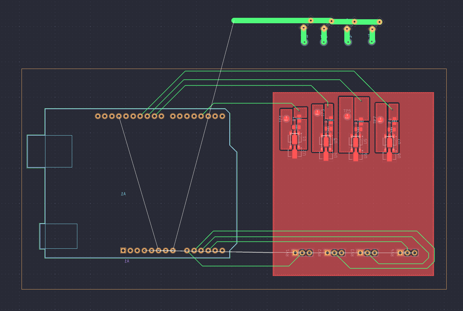
I’ve been busy with other projects and haven’t really had the time or energy to take on the Sunlike task light I has originally planned (also ran out of budget for supporting components). Going to stick with stuff I already have on hand, thinking of a custom RGBW light that could potential have Home Assistant integration down the line, using 7135s and some copperboard as I don’t think I can get PCBs made in time. Plan is to 3D print a chassis (PETG happens to be what I have so it will be black gloss haha). Started a rough KiCAD schematic to plan out the board layout, unfortunately I don’t have any CNC available so I will have to manually cut my PCB traces with a dremel and engraving bit.
I know Hank of Emisar/Noctigon sells E21A Azure in some lights. Not sure if he sells them separately but you could always ask if you can’t find them elsewhere.
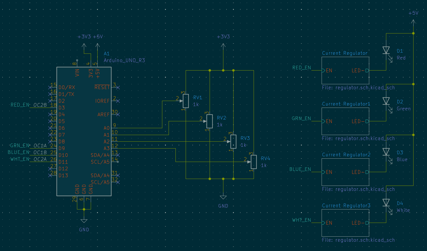
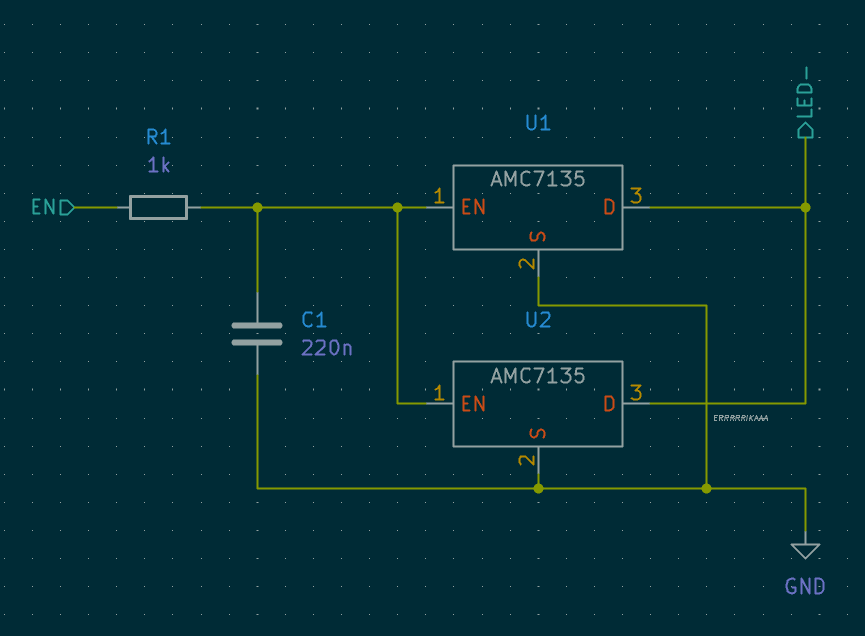
I’ll be using an Arduino to drive the LEDs as the originally planned Pi 4B got fried in an unrelated incident. (nothing else I own can do HomeAssistant natively anyways). The PWM output will be fed through an RC filter to make sure the LEDs don’t flicker:
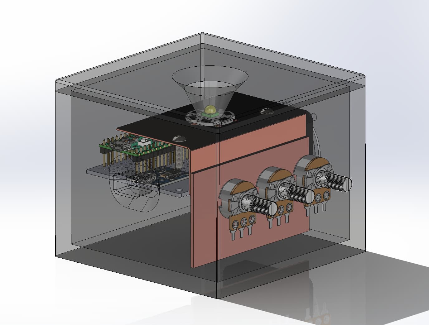
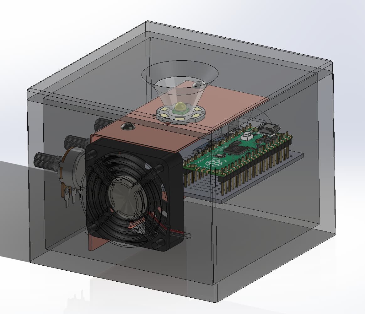
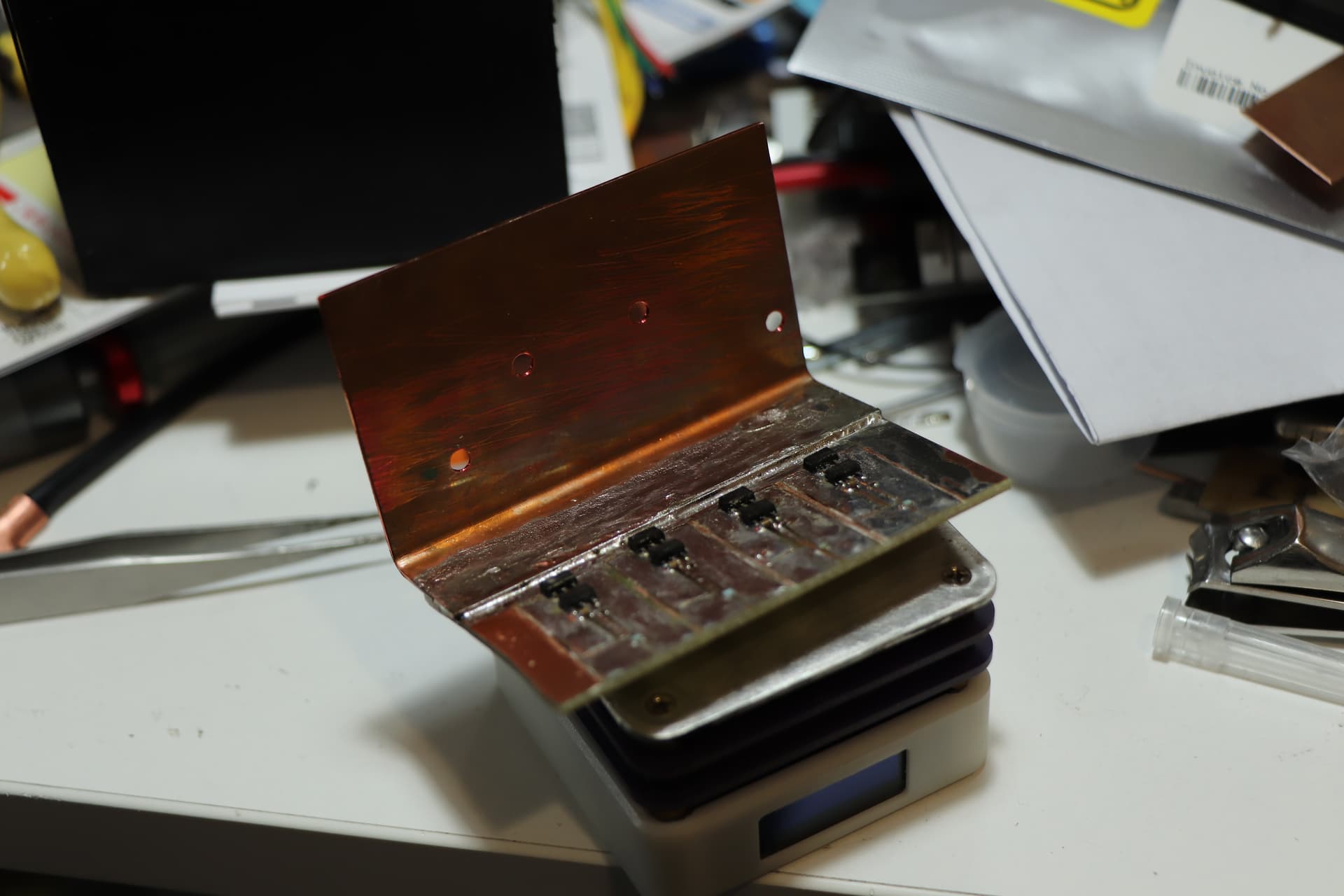
The MCPCB will be screwed down on some 0.8mm copper sheet, and heatsinks attached to that will help dissipate the heat. I’m not expecting much power dissipation as it’s only 700ma max per channel (2x 7135s), powered off a small li-po cell. I may also try stuffing some 18650s in there, but currently the case is too short for 21700s.
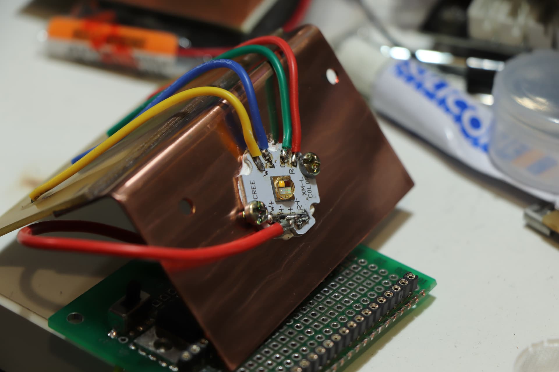
Using pots to control each RGB channel for the time being, looking into adding openRGB support later. Still not sure what to do with the W part of the XM-L RGBW…
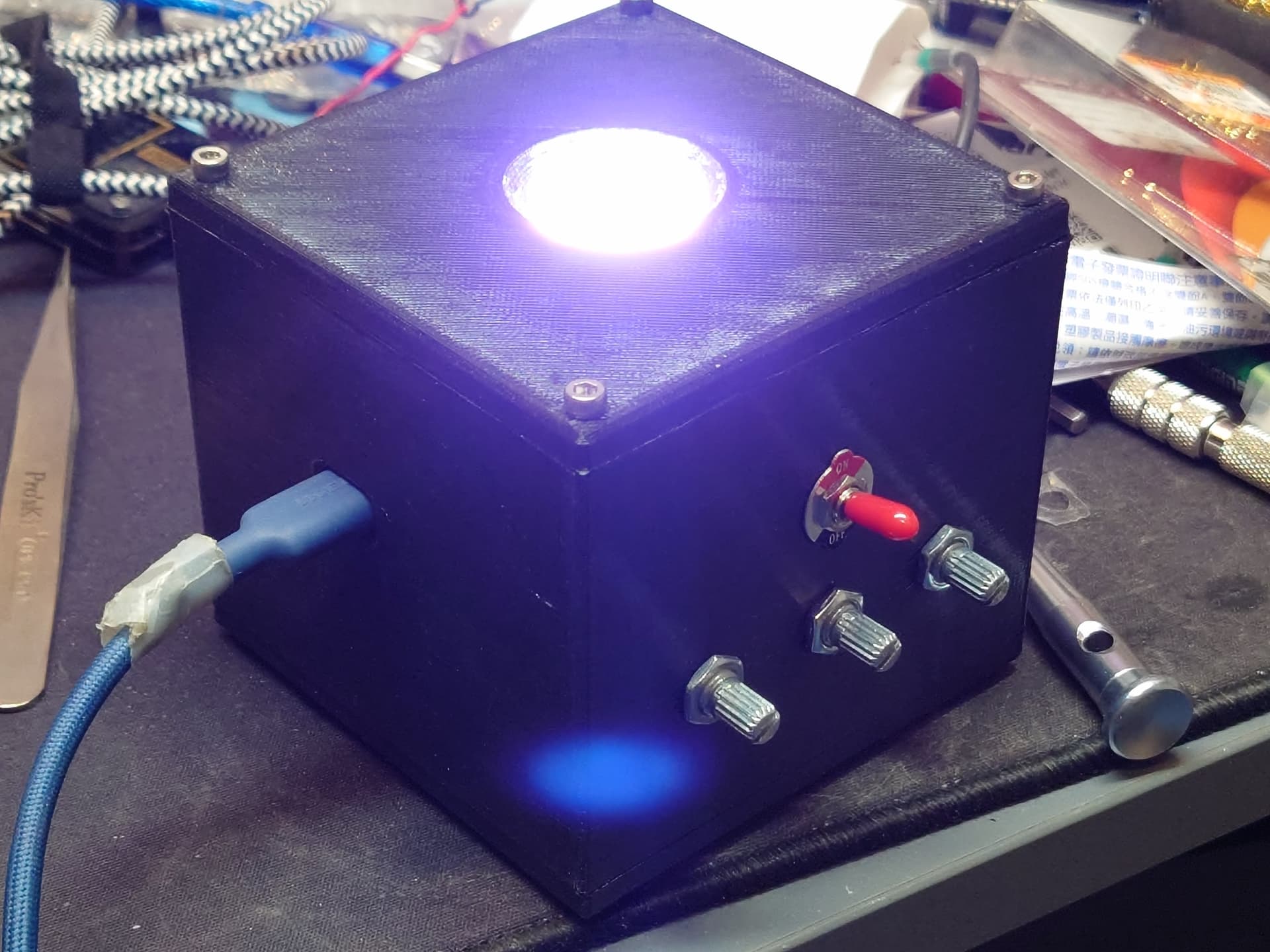
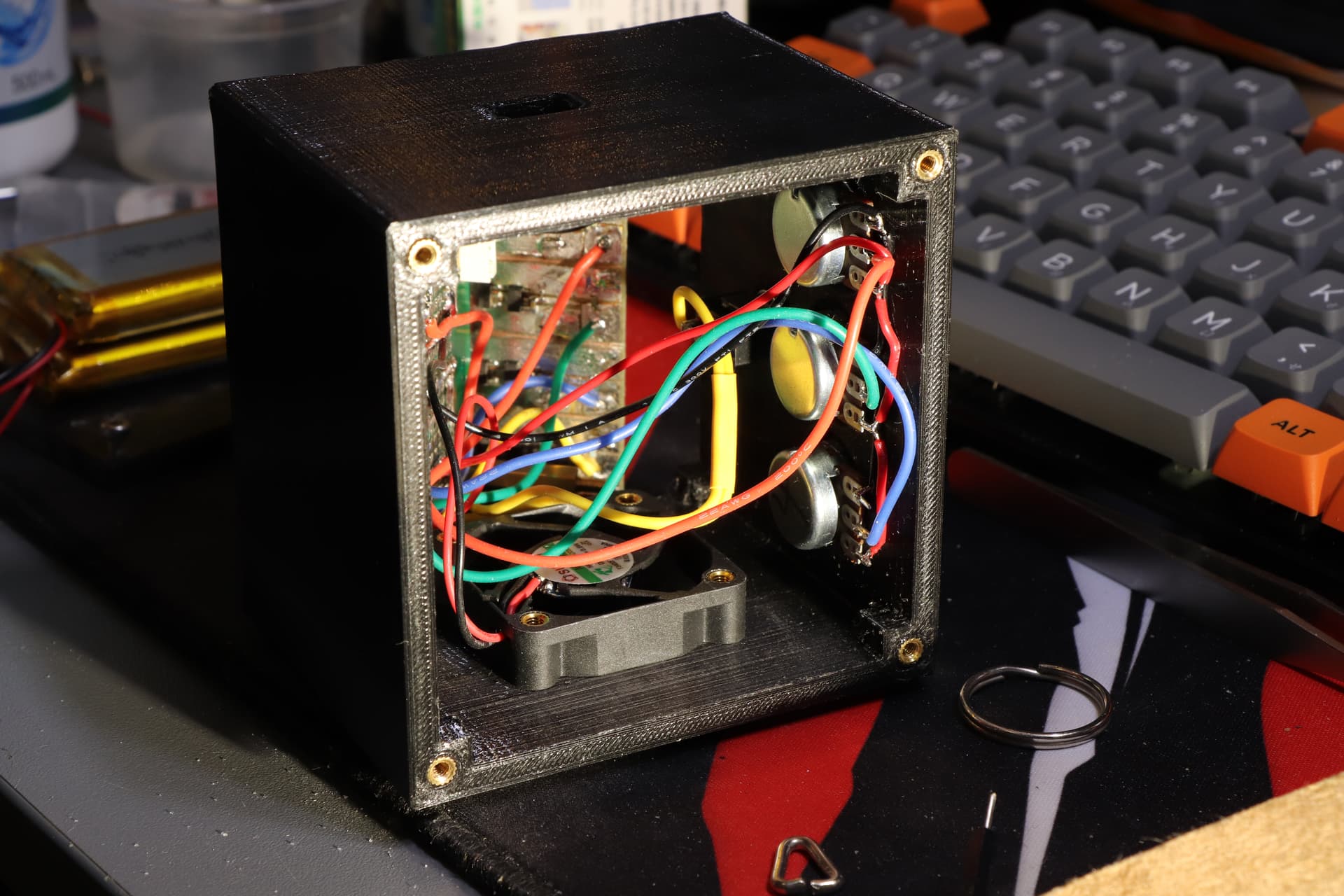
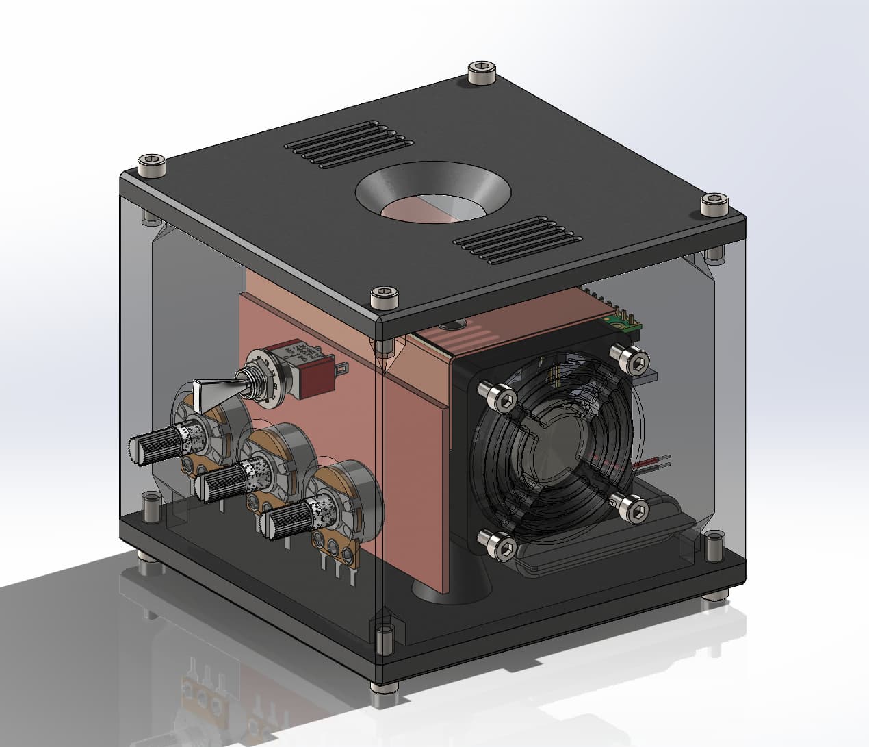
I’ve assembled the light with some placeholder code - it just changes brightness of the R, G, B channels via the pots. I was worried about the linear driver I made overheatng, but it seems that slapping it on a hunk of copper has solved that. If it gets too warm I can still add more heatsinks, the tiny 40mm fan really helps with a small amount of forced convection.
I ended up swithching to powering it off some pouch cells, in total it has 8.4Ah nominal capacity which should last a long time given it should only consume 3A max with the 8 7135s on board.
Somewhat put of updating the thread as I went through with the build progress so I guess I’ll dump the photos I took and explain them…
Planning the build:
I didn’t really have much of a plan with this, most of it was just eyeballed throughout it. I had an RGBW LED, some current regulators, so decided on a custom RGB light of some sort. Originally I had planned to be able to manufacture stuff using a lathe or a mill, but ended up not having the time or resources to make something that sophisticated - I stuck with just 3D printed parts and some hand tools I already had. Since this would be made of stuff I had on hand I looked through my parts bins and also dug out a beaded TIR for the LED, since the emitters would all be off-centre as well as some perfboard/copperboard for the electronics.
The original plan I mentioned above would’ve involved a custom switching driver, but I ended up not having the time to design or test one in time for this contest, maybe next year? I still wanted to make a custom driver (partially since I didn’t really have the budget to order more and I still haven’t had much experience with modifying anduril), I settled on originally using an Arduino Uno as my controller as it had enough ADCs and PWM outputs for what I wanted - individual dials for each RGB channel. Using KiCad, I planned out a rough layout for the driver circuit - just some 7135 regulators and an RC filter:
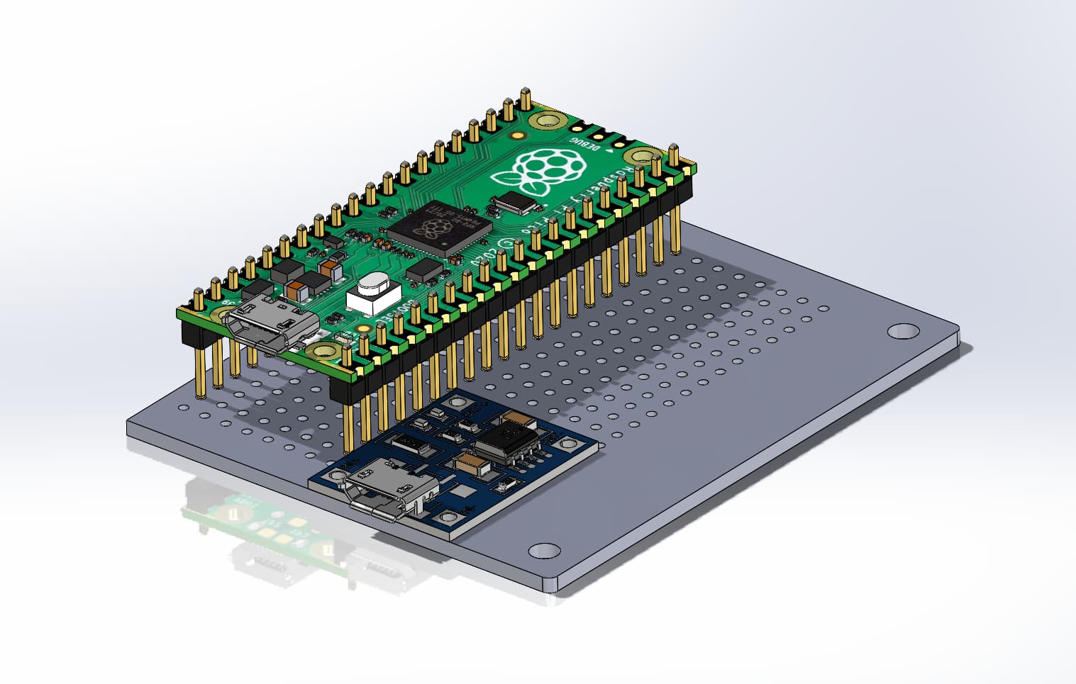
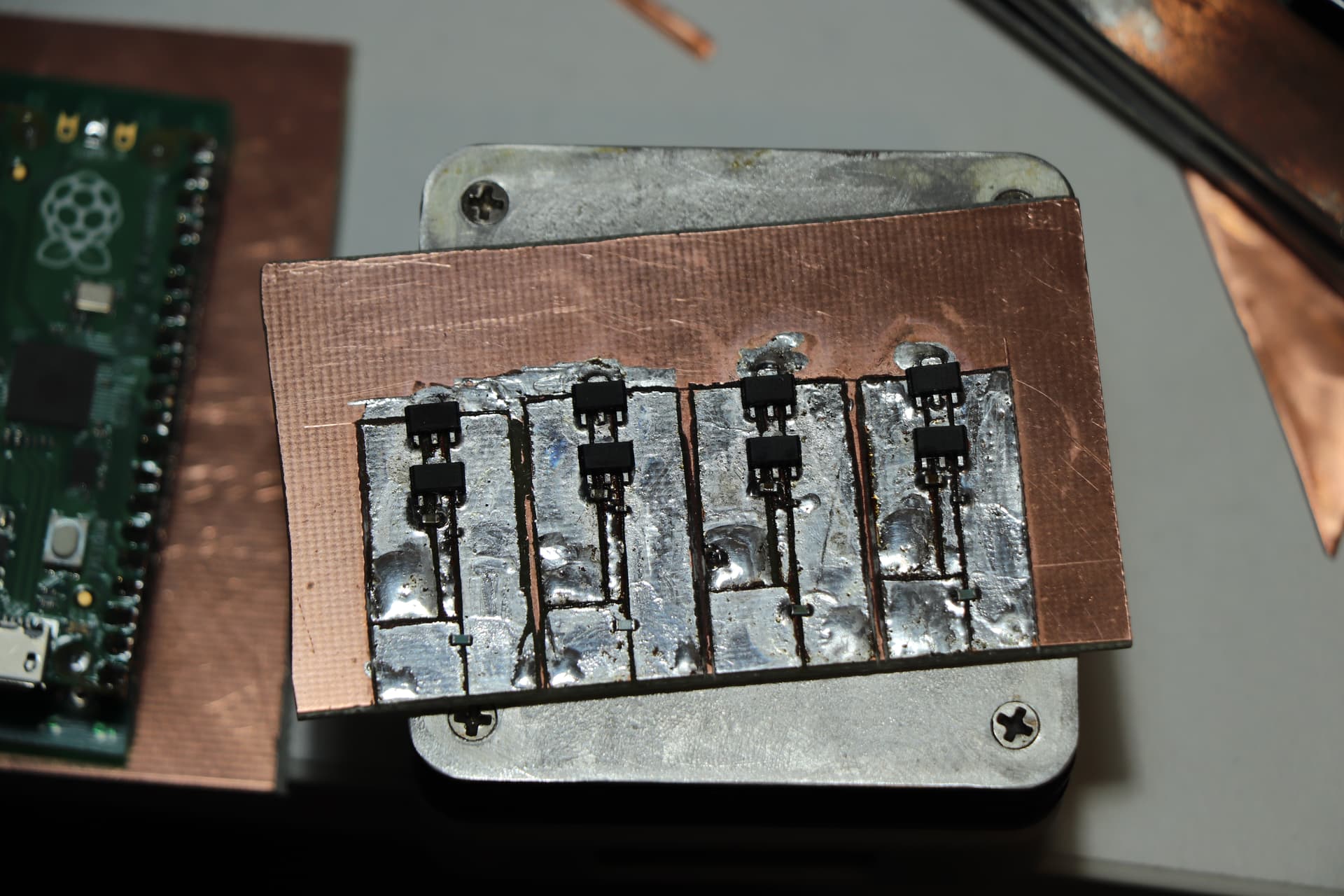
I ended up switching to a Pi Pico as its footprint was a lot smaller and I could write more spaghetti code should I need it. It also allowed me to mount it to a perfboard as the Arduino has a small whoopsie in the design resulting in the headers being 0.05" apart from each other instead of the normal 0.1" spacing. The perfboard and driver board can then be attached by brass standoffs, with the 0.8mm copper sheet (I have a lot of random parts just lying around, lol) to screw the MCPCB onto.
Actually building the light:
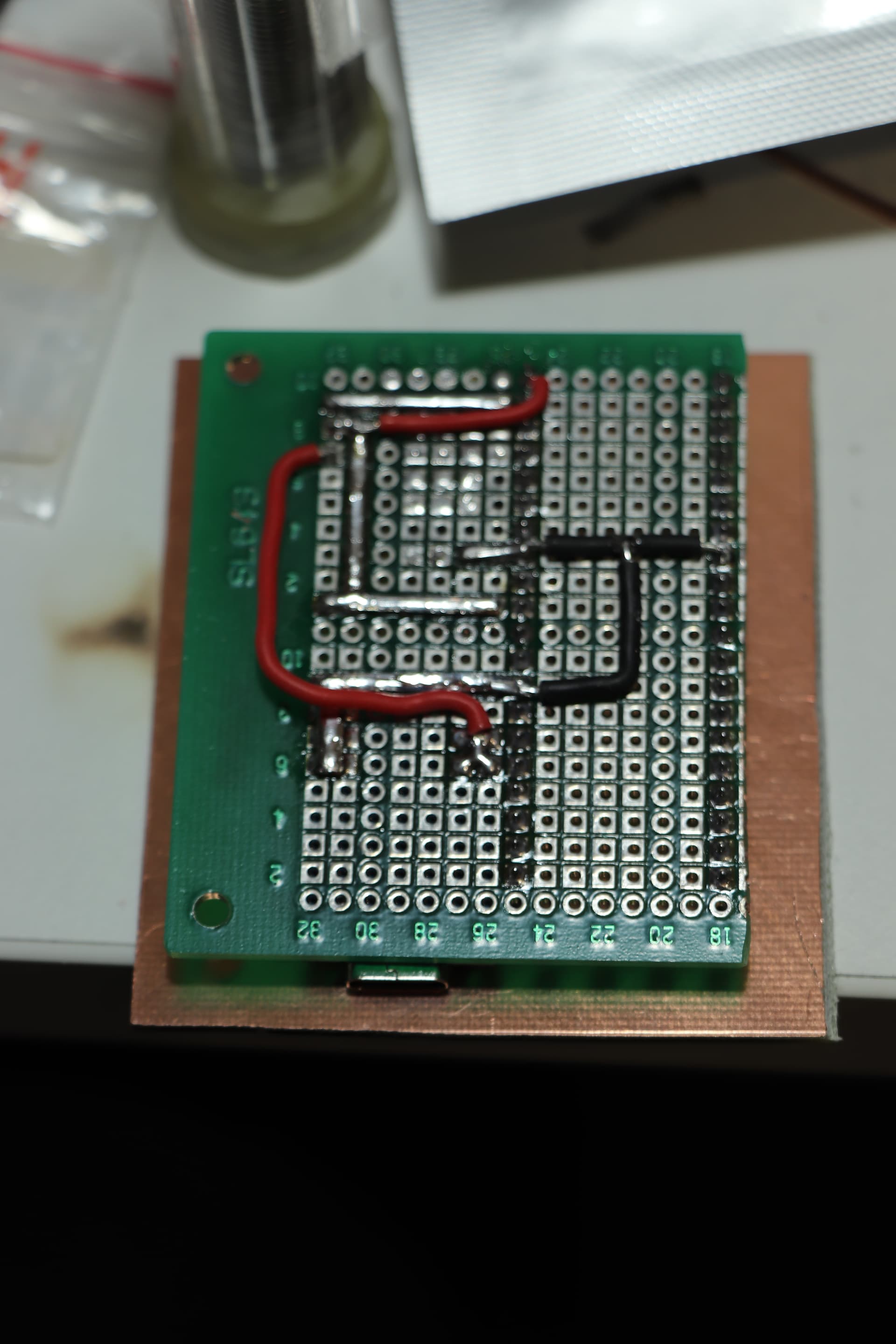
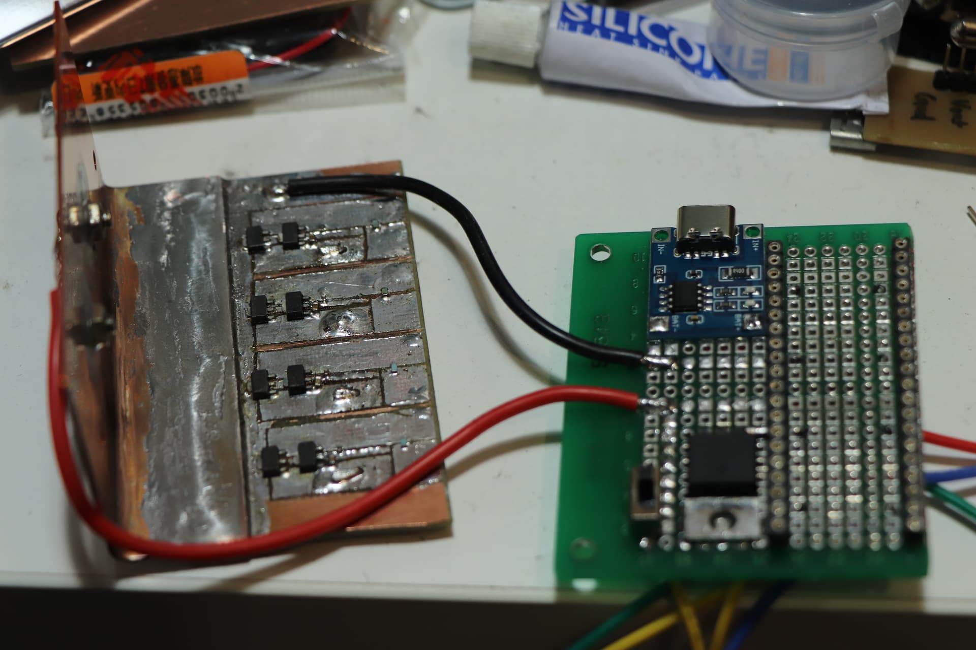
The KiCAD file was just a rough layout done in 5 minutes to give me an idea of what cuts to make on the copperboard - later on I used some calipers to mark out the cuts and a craft knife to carefully score through the copper:
I found some pretty nice gold plated turned pin headers instead of the generic square ones that ended up being lower profile and much nicer to use. Those were soldered first on a chunk of some really nice PTH perfboard and the corresponding pin header on the Pi Pico (they’re not compatible with normal DuPont style headers unfortunately). In hindsight it probably would’ve also been a good idea to make a mock-up of the perfboard in KiCAD, but there wasn’t that many wires to connect. I also chucked on a generic TP4056 battery charger module along with a chunky LDO, which didn’t end up getting used (originally planned to make it run off a wide voltage range, cause why not, but didn’t have the parts to properly OR it with the TP4056 output without something going boom). Might desolder it later to salvage it. I ended up using some scrap copper from offcuts as busbars, they’re complete overkill but looked nice and were much easier to solder than the stranded wire I had on hand.
Anyone know how to make these go side-by side? Apparently tables are still broken for mobile view
Started cutting the copper I was going to mount the MCPCB to by hand with a junior hacksaw before realising halfway through that my uni had a sheet metal guilltine I could use…
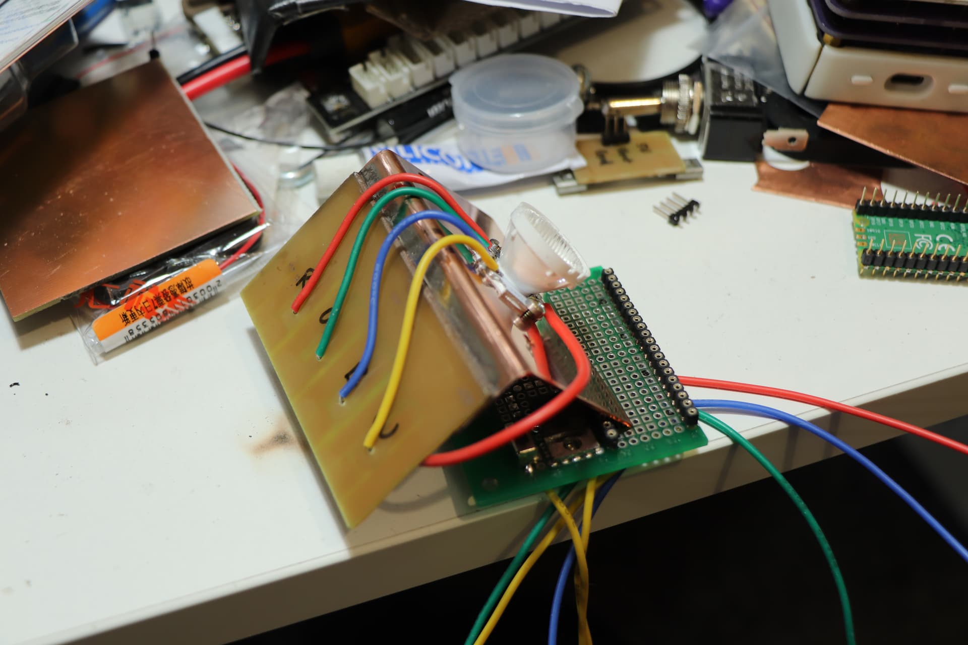
Used some silicone wire to connect each channel up to each driver. I still didn’t know if I was going to use the white channel and just added it anyways. Since the regulators are low side I wired up the MCPCB in common anode configuration, bridging all of the pads with another bit of scrap copper.
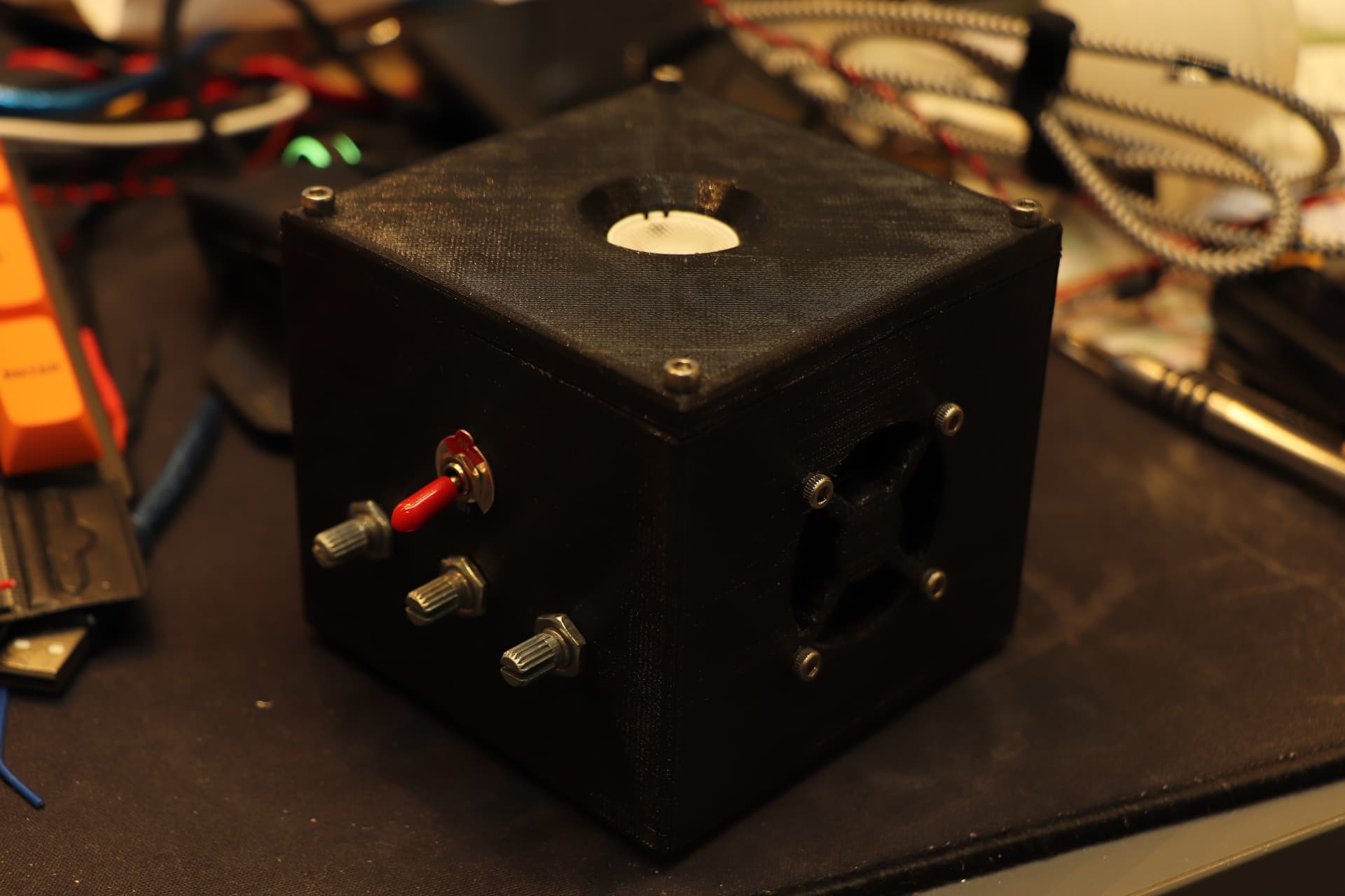
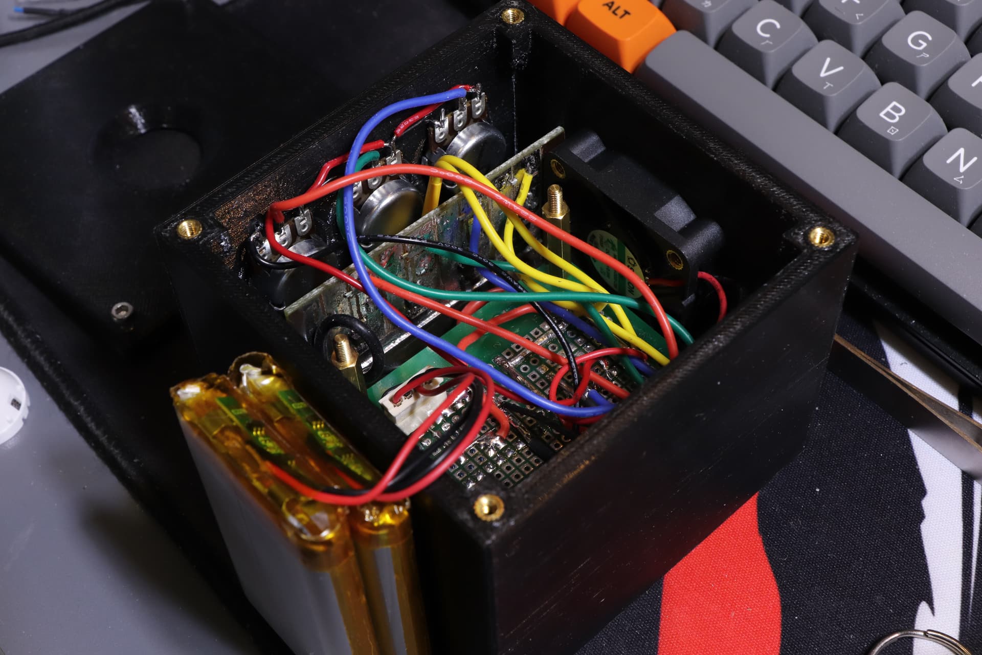
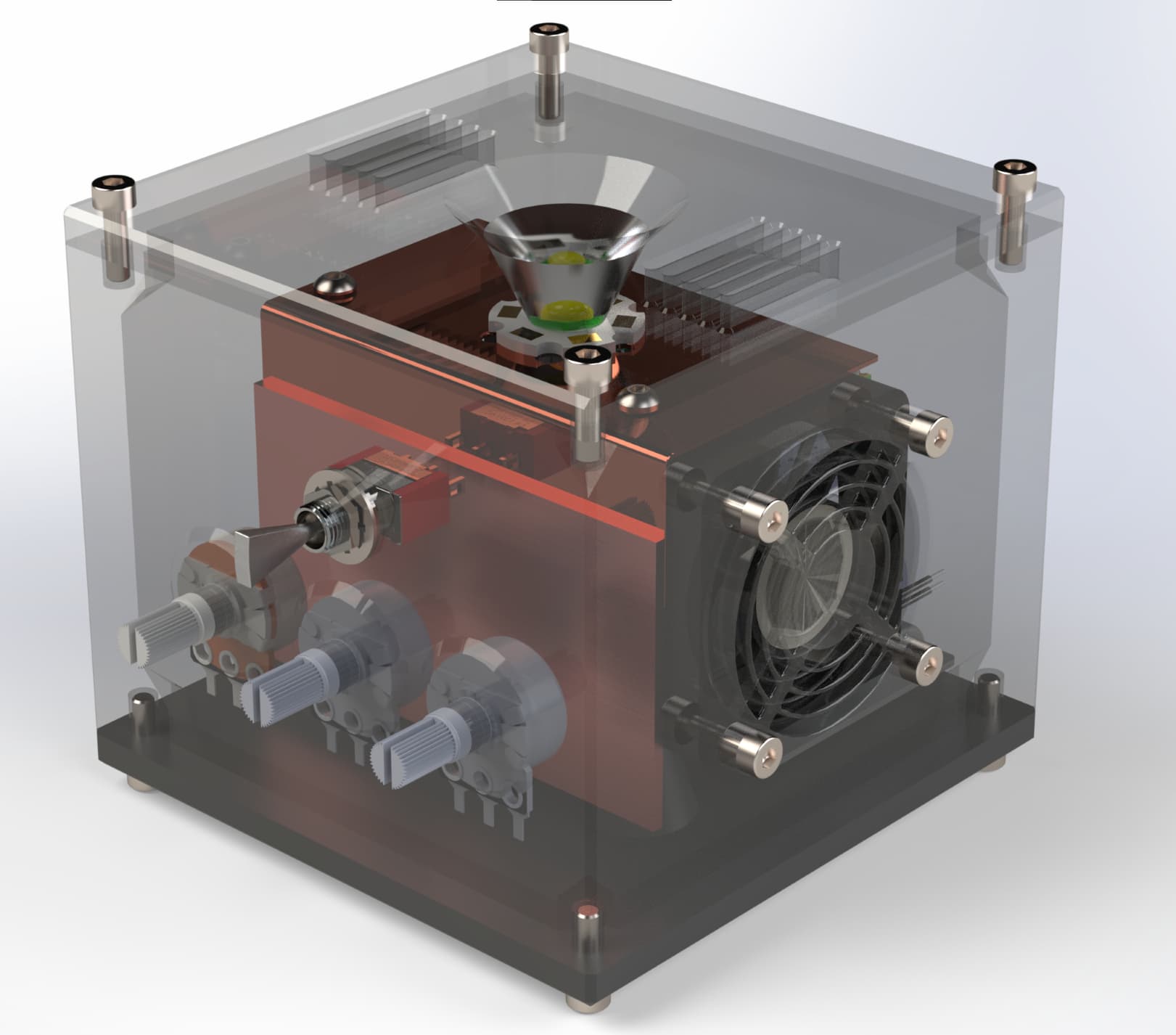
By the time all that was done the 3D print had finished, so I decided to do a test fit. My printer didn’t have enough resolution for a proper fan grille, ended up replacing it with a tiny metal one (not shown until later as I forgot to put it on during the test fit)
I also added 2 4200mah pouch cells, giving this a few hours of runtime. Unfortunately as it’s using a TP4056 it would also need to be charged overnight, a minor oversight. Some of the wires were left a bit too short, resulting in a bit of spaghetti wiring in the light to get stuff to fit.
A later revision in the CAD model would include vents in the lid, I may have take the wrong one with me when I went home for Christmas so it will have to do until I return. Some forced convection is better than none, right?
I’m currently rendering final images, sadly I don’t have my eGPU with me so will have to do with a much lower power laptop GPU. Will update if they actually complete…
Welp, the rednering softwarre crapped itself overnight and decided to get stuck on CPU render only…