Solarstorm SC02 mod with R,G,B,W,UV. So many 7135s!

EDIT 7/30/2015: I made a build video here: https://www.youtube.com/watch?v=bg5njtFVszA

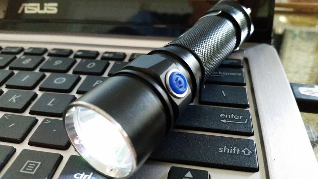
Here’s a mod I did this week on a Solarstorm SC02, which is an Olight S20 clone. This is a pretty nice light for $15: nice machining and good overall build quality. But the UI is awful! I know my mods are getting a bit repetitive, but I’ve reached the point where I can’t stand to use any light that can’t do absolutely everything, so I had to put MELD firmware into this one as well. The big difference here is that I build up the hardware from scratch instead of using a PCB, since this one is for rechargeable cells only. So here’s the story of how to pack way too many 7135s into a tiny space:


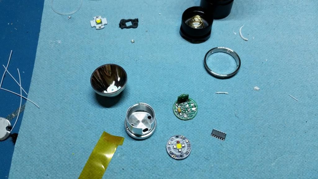
First I gutted the light and stripped everything except the capacitor off of the driver


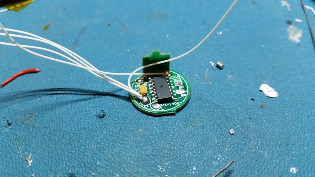
Then I glued my PIC16F1825 upside-down on the board


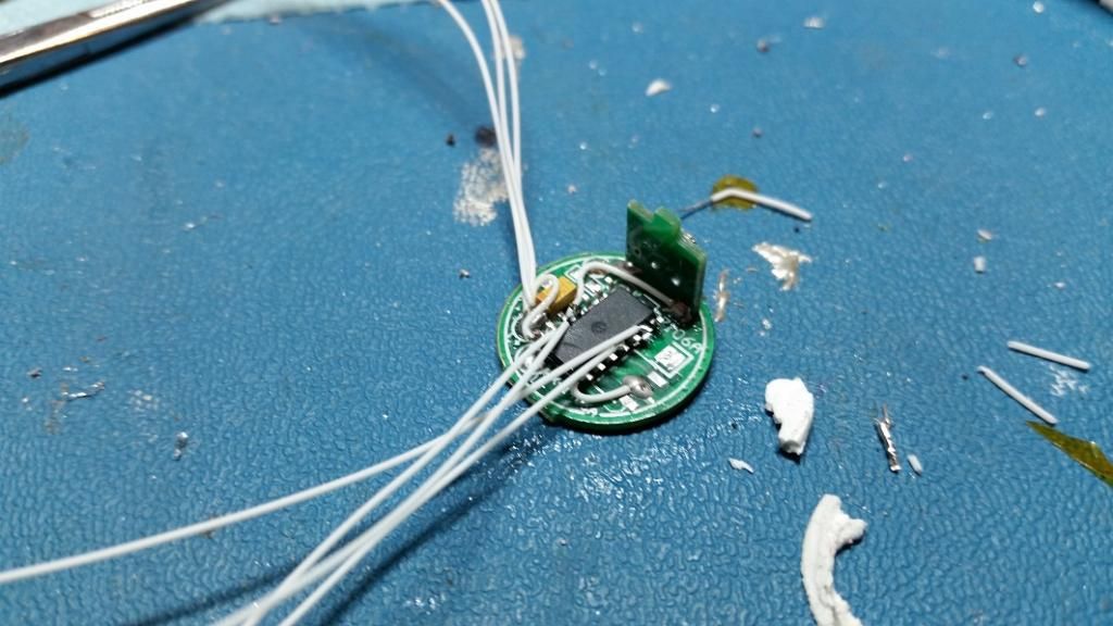
And started tacking wires on. The PIC needs 7 connections to it: power, ground, switch input, and four PWM outputs.


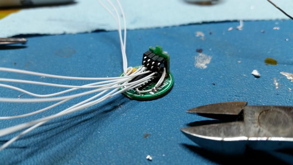
I started stacking up the regulators and wiring them in. This set of four is for the color channels, which get just one regulator each.


And this set of 6 are paralleled to run the white LED. They’re arranged in two sets of 3 to share current between two sets of wires and for mechanical flexibility


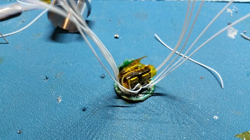
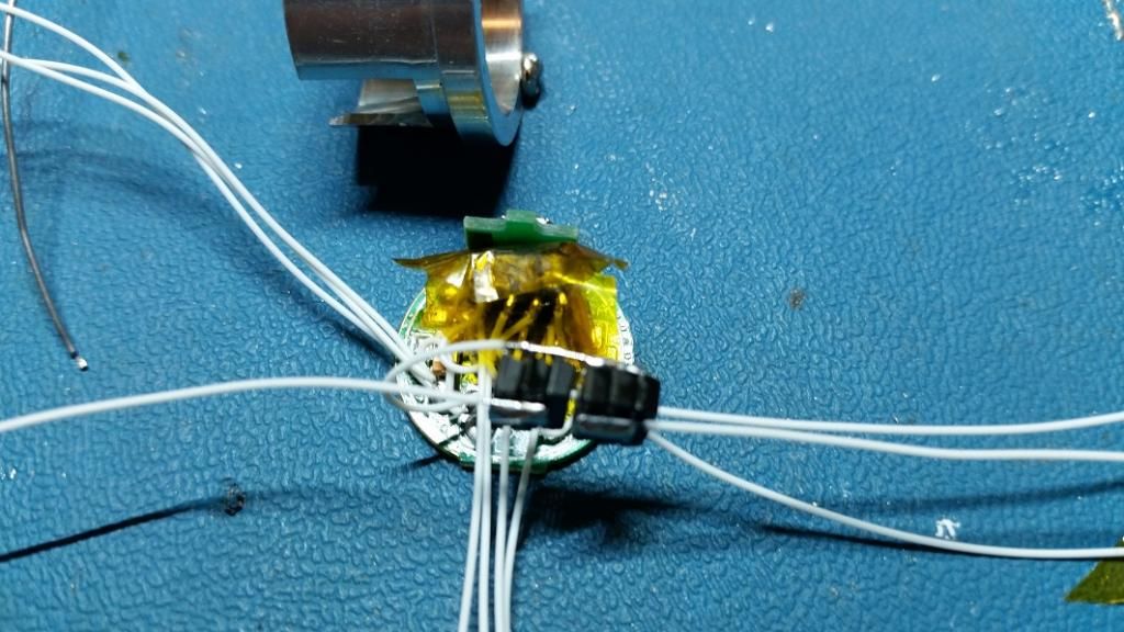
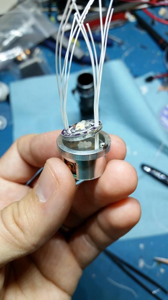
Here’s everything wired up, insulated, and the wires bundled to go through the holes in the pill


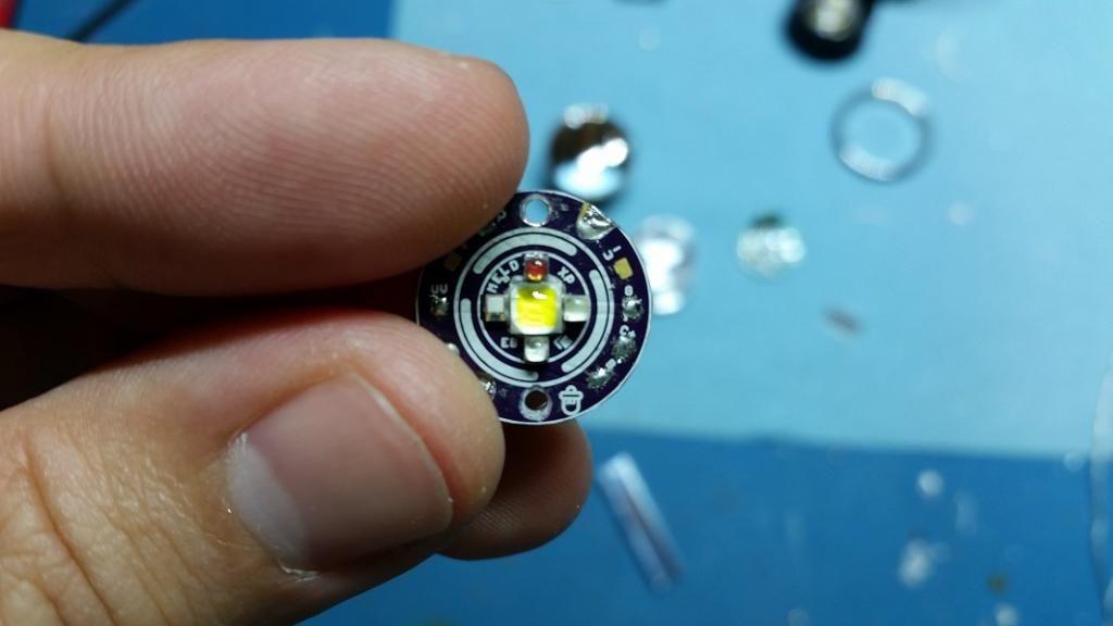
For the LED board, I build one up from and aluminum XP star and one of my custom PCBs, using the two-layer technique I came up with for my Blackshadow mod. This gives the white LED (an XP-L) plenty of heatsinking but still fits in the colors in a very small space.


Here are the wires feeding through the pill and LED board, with some thermal grease in place.


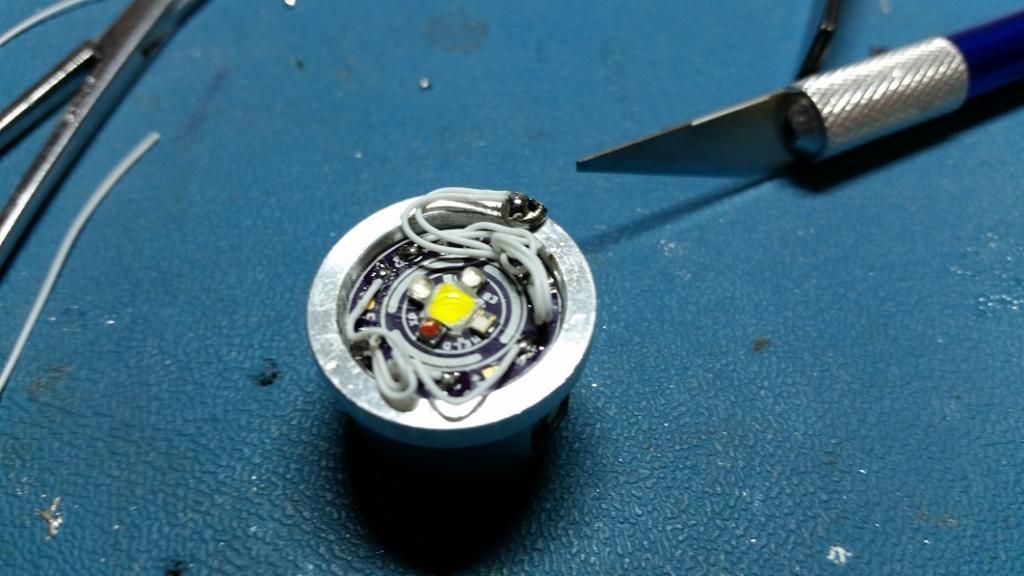
And here’s the result of the (tedious) wiring process


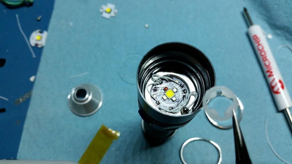
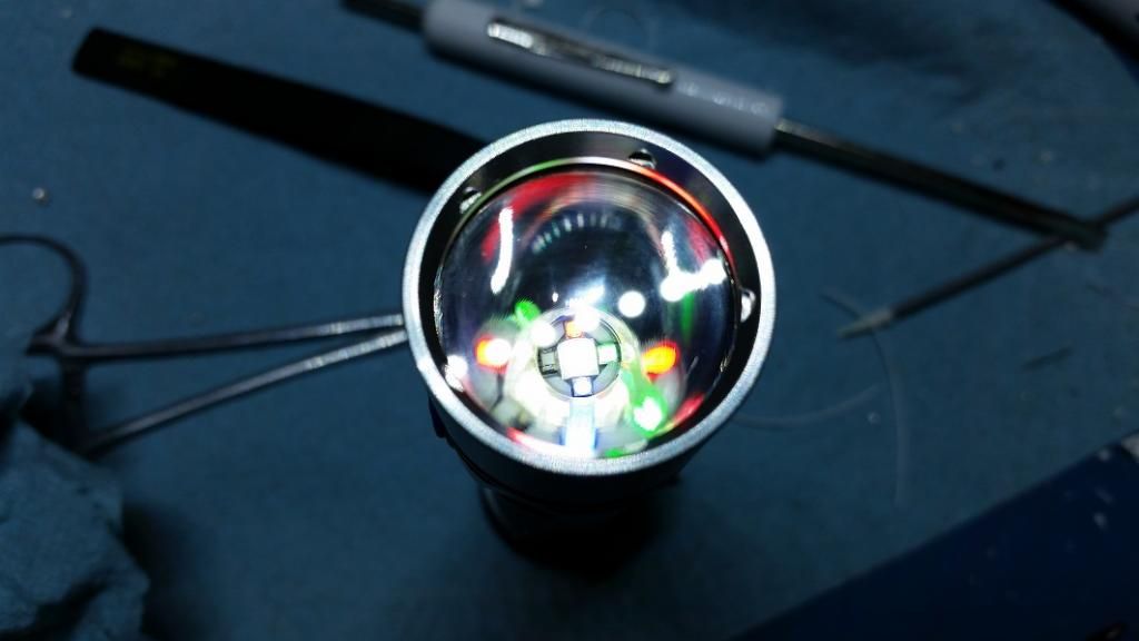
Finally, I cut up the original LED insulator to fit around all 5 emitters, and put it in place under the reflector. This was necessary to match the original height stackup which puts the necessary pressure on the pill from the front bezel.

And done! This light runs version 2.13 of my MELD firmware. A few improvements have been made since, but this demo video gives an overview of the firmware

Update: here’s an overview video of MELDv2.13 firmware:

And here’s the configuration menu:

Really nice, I follow your projects for some time. I hope one day I purchase a flashlight with that interface.

Jesus Christ. That was a lot going on for a flashlight! I loved the darpa puke light, and most of the modes in the 6-8 minute frame.

You should consider selling a light like that.

I do sell microcontrollers programmed with the MELD firmware for those who want to make their own like this, and I also do mod jobs for hire for those who just want the completed light.

how did you get the pill and the driver out? are they just pressed in? did you have to pull the switch boot and retaining ring? is the retaining ring a press fit?

It was really easy. The whole pill is very lightly pressed in, and the switch boot can stay in place the whole time. After removing the bezel ring, lens, and reflector, you can just push the pill out by putting a battery in the tube and pressing on it. The driver is a loose press fit in the pill and pries out easily.

thank you for your reply. you did a beautiful job on the light. the intricate wiring is very impressive. I have several SC series lights including a couple that don’t work and plan on doing some mods of my own.

if you plan to build more stars like that one with the 5 emitters, i would definitely buy one.

Epic!

That is beyond cool, so many modes, I like it.

Dude I have the same light apart on my bench right now, guess what I’m doing to it lol.

Edit I’ve always wondered, what’s the white wire you use? It looks solid core.

Edit2: having worked on both original S20’s and these this is the better light in every aspect but glass quality and ano, the inside if the switch is a way better design (that doesn’t rip when taking it apart) and the pill presses in with much more contact.

tterev3 I went ahead and designed a board for mine using a QFN, once I finish it up I’ll send you the files.

Sounds awesome, did you use the transistor arrangement that you used on your other drivers? How will you mount the switch? It would be great if you managed to reuse the stock switch daughter board on yours.

The white wire I use is 30AWG solid-core wire wrap wire. I can’t remember the exact one I bought but it’s similar to this one: http://www.mouser.com/ProductDetail/OK-Industries/R30W-0100/?qs=sGAEpiMZZMtW9UaYX5J1tA5kwbIAvdfRQwwnziThR3k%3D

The boards themselves are open source, here’s the XP version and the XB version if you’d like to build one yourself, but I’d be happy to make some for you. I keep all the parts on hand to do both the basic and the metal-core two-layer version I used in this light.

Note sent.

Can’t get over all the options.
Fantastic.
PM sent.
Thanks,
Keith

Yes for the main white emitter then one 7135 each for the colors. Yes I used the factory daughter board for the switch (it’ll be interesting to see if I did the slot right, I know its in the right location but I’m a little worried about if its actually gonna be cut out, I submitted the design before I read the stuff that just got posted yesterday about how to make sure cut-out’s get done correctly, may have to end up doing some file work once they get here, the render looked right but that thread about wight’s contact plate’s coming out solid concerns me).

I was considering making a new daughter board with one or two 7135’s on the bottom of it but I was concerned about the thicker boards from oshpark not working for some other reason and I also never made a daughter board that uses connections like it does (only via header pins) so for now other components on the bottom lost out even tho I really liked that idea.

One thing I’m really not thrilled about is I couldnt fit a 1206 for the sense resistor, only a pair of 0805 pad’s, what is the next size up from 0805? I plan on standing 3 or 4 0805’s on their sides on the 2 pad’s (not touching) to try to have good enough dissapation to air but I’m thinking current is going to be limited to about 1.5A for white so it doesnt burn up, calculations say anything over that needs minimum 1W ’s (which is why my 17mm 4ch transistor driver uses a stack of 1206’s per ch to be able to add up to the power level I needed for 2.25A)

are you MCPCB’s DTP or with a mask under the main thermal pad?

edit whats the size of the R030 sens resistor on the stock board?

Incredible!

I just used a standard MCPCB with dielectric layer. The stock current sense resistor is a 1206

never seen anything like this. super!

I did a new firmware overview video for v2.13:

And here’s the configuration menu: