Nope, the resistors are going to one leg of the 7136, grounding LED- would bypass everything and it'd be on all the time. Very similar setup to the newer 3-FET/linear/no-toroid SRK drivers.
comfy - is there any way to go direct drive then, but still have modes and driver control? It sounds risky to me for DD...
Bypassing the sensing resistors will disable current regulation or would increase the regulation so much that it is similiar to direct drive…
Yeah I'm thoroughly confused now, after going back to the SRK drivers. They ARE current limiting resistors - on both the old style 3-toroid one, and the newer 7136/linear driver. The resistors are the FET's only path to ground, and since the LED- can only get to ground through the FET, that makes them limiting resistors and not current sense resistors.
To me, it appears the 7136 & FET are in parallel, and I can't figure out what the 7136 is doing in there. :~
Well, I guess I might just remove the resistors and use a piece of wire to bridge. That will lower the resistance to almost null.
It looks about the same driver as I got in one of the king clones. Current limiting with the 7136 having a 50mV current limit feedback? Same set-up as I had before. I do have some .001 resistors. I could just use one of those on each leg.
I can explain how the circuit works I have researched it before modding my M6.
The 7136 can be used as constant current regulators, the current gets selected through the sensing resistor.
The 7136 can be used with an external FET to enhance the maximum current, this is done in the flashlight drivers.
The vin pin of the 7136 is connected to the Pwm output of the controller to make the modes. If duty cycle is 100% the current to the led is the one selected with the resistors, in lower duty cycles the resulting average gets reduced. The pulses are always the selected current. So I would recommend to just solder some r100 parallel to the stock resistors, this would give a real world direct drive but spikecurrent limiting in lower modes…
The sensing resistors are always in the direct path of the led!
The controller(in this case 7136) measures the voltage drop over the sensing resistor to determine which current is flowing to the led. It is necessary for the feedback to measure the current.
What I'm stuck on is that the resistors are acting as sense resistors for the 7136, but also those same resistors provide the only ground path for the FET's source pin. If the FET had its own separate ground, and the 7136 had its sense resistors, sure, I would get that.
Would it be possible to lift the FET's source pin and give it a straight no-resistor path to ground?
Then the sensing resistor couldn’t measure the current through the led because the current would flow not through it. ![]() without measuring you aren’t able to regulate it to its constant value.
without measuring you aren’t able to regulate it to its constant value.
On most sensing drivers the positive line has the sensing resistors in series and the FET source is connected to ground.
That’s the same because the sensing resistors are in series with the LEDs in every case.

So... the multiple very low value resistors are low enough resistance that they don't significantly limit the LED's current, but give just enough resistance for the 7136s to measure?
But I think most of us are looking for as close to direct drive as possible, while still keeping well-behaved operation in lower modes. I don't have one of the 3-channel FET based boards to play with right now, just the older 3 toroid ones, and they do OK with the resistors completely eliminated/bridged. That driver is different enough I don't know if it's really relevant to this type though.
Stock resistance is 26mOhm per led gets even lower with additional resistors.
The FET onresistance is also in line and probably in the same area…
Not sure about the spring because I haven’t got the tailcap off.
That is not perfect for maximum performance in insane mods but I use mine with current of 3.5A with dedomed xml1 and one XML is even half defect and this light makes a lot light and gets hot very fast on high. I use it most of the time in mid mode which gives around 900lm.
Is on the new driver still the PWM pad next to the controller?
Can someone measure the stock standby current?
If someone is brave and wants to try my mod I would be glad to provide my beta firmware which runs on a nanjg…
Werner -
Umm, not sure what to look for... What's a PWM pad look like? Ooops! I see it now in the OP. My pics are covering up too much - RacerR86 did a better job by shifting the wires in a 2nd pic... Maybe I'll add 1 or 2 more pics.
How do you measure standby current? Ohhh - I'd have to wire up a battery with th light off. Not sure if my DMM goes that low?
For your driver, is it one short touch OFF? Really want that, if so, I'd be interested in trying yours. I can program/download Nanjg's.
(ugly Pics deleted)
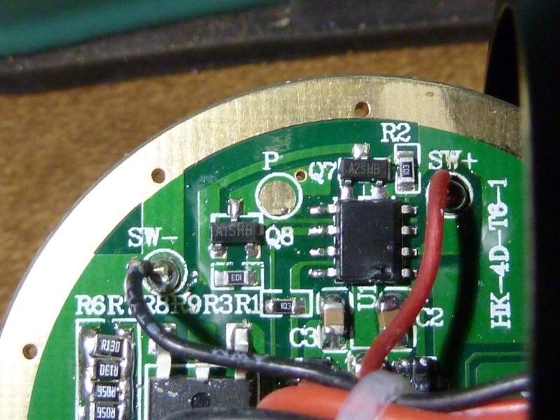
Yep seems to be the P pad. But there are additional items a1sh8 seems to be a transistor(not sure google says something like that….) I can’t see the traces and the writings on the other sot23 device…maybe you can make a picture with more light or flash…?
On my driver the Pwm pad is connected to the leg5 of the controller and goes through hole and on the other side to every 7136.
——
I have 6 modes including off, fast click increases brightness longer click reduces brightness. So you can switch the light from offstage on in either highest mode or lowest mode, that comes in very handy.
I thought about different UI but this one is kind of perfect. Three fast clicks(you can click almost as fast as you can) are the mid mode.
Sadly I have no stock light to test it, if wallbuys had stated that they were selling xml2 m6s I would have bought one too.
I have removed all the small items from the PCB (controller, two sot23, diode, capacitor) maybe you can find a way to do this a bit more gentle.
I also have dedomed emitters which are all different so no good test circumstances.
The firmware works and I have it in my light since longer time but I have to work on low battery warning and on standby mode.
Yes only connect a power source inline with your DMM on lowest current setting in series, I also doubt that my cheap DMM are very accurate but I want to get a clue of the stock status. No big deal on this light anyway because it can be locked out easily and it has huge battery capacity…
If someone is willing to test it please let me know when you will have time for it so that I can send you the latest firmware…
I had ordered 3 different electronic switch lights from wallbuys end of November to do tests on my own but they have not reached me yet…
Me me me me me! I have sitting around here, I dunno, like 6 completed SRK-style lights, and 3-4 bare drivers, all of which are stuck with the crap UI they all come with. Some original 3-toroid drivers, the crazy 15+ amp single FET driver from the 'Securitying' clones, the one from the 6XL2 with the dumb low output FET (planning to find a replacement that works like the good K4212 FET)... and I have a pile of 105Cs yet to be flashed with something useful.
Here's a better shot:
I used a desktop tripod, 2 sec delay, and a neutral EDC with TIR on low, with my somewhat dated Panasonic Lumix DMC-ZS7.
Thats a perfect picture, I often use the blfA8 with diffuser cone as a photo light. With enough light even my phone camera makes sharp enough pictures to read all fine writings too.
——
They changed the layout a lot, these two FETs are new. I have no clue what these are good for…if you remove the controller please make an additional picture.
If I get this right the nfet drives the pFET which is connected to the 7136. So this is maybe just a kind of driver for the 7136s…?
I can confirm what Daylighter noted, the tailcap removes with ease on mine as well. Heated it up a little, then easily unscrewed by hand. Maybe showed a slight trace of glue, can't really be sure. Very unlike my FandyFire UV-S5 tailcap, which with heat and strap wrench's won't budge.
I added 2 R100's per bank (6 added total) and got the tailcap reading up to 10.8A, and about 3,400 OTF @30 secs -- nice bump, still stock XM-L2 LED's.
Updated:
tail amps: 10.85A, Lumens: 3,400 @start, 3,284 @30 secs, throw: 44.5 kcd
Hi Tom, Will you please shine the M6 at your luxmeter if you get a chance?
Thanks
Oh, for throw? @work now, maybe this eve. Brought it to work with me, and it does seem to have a nice hot spot - wondering if anyone posted kcd #'s on it. I know Ricky (manxbuggy1) has got a hotrod version from Dale (DBStrm) that does like 3,900 lumens, not sure of throw. Maybe Ricky did the measurement - you could pm him.
How'd you make out with your M6 modding?
This is what I did to my M6; Installed XML-2 U2 1A’s on 16mm noctogons, removed aluminum in reflector area to keep from shorting, removed all SMD sense? or current limiting? resistors and built a solder bridge across 4 pads on all 3 channels. When I put the light back together I picked-up about 15kcd, which was less slightly less than I expected. Upon further inspection I noticed 1 emitter wasn’t working (not sure if all three were working when I tested the light stock). Disassembled light and tested the LED in question with an outside power source and it worked well. Inspected and resoldered some spots but no change. When taking the positive wire to the LED and moving the ground to other spots (outside ground ring or grounds to the other LED’s I got what looked like full light). My temporary fix was to disconnect the ground wire running to the LED in question, from driver board in L2- position and solder that wire to L- along with the with the wire that was already occupying that spot. This lights all 3 LED’s and allowed me to pick-up another 11kcd but I fear that this “fix” will damage some other component on the driver. Any help you could give me on this would be greatly appreciated!