Thefreeman high power/efficiency driver development. Update : SP36 130W boost driver

Until now I have been making high efficiency drivers for single cell flashlights, with good power for the size but nothing really crazy. Due to space constraints I’ve always used DC-DC converter integrated circuits, that is the DC-DC controller and the power MOSFETs are contained in a single package allowing small sized power circuits, for example the MP3431 boost converter or TPS62867 6A buck converter.
At higher input voltage than single li-ion cell there are relatively high power buck converter ICs available, like the 20A buck I used in my cascaded boost+buck driver, but that wouldn’t have been high and efficient enough for my project, the solution is to use a buck controller with external MOSFETs, allowing to use very low ON resistance FETs for lower conduction losses, and low switching frequency for low switching losses.

For the dev platform I chose the Amutorch DM80 for a few reasons :

  • 3x21700 cells in series providing high enough voltage for full regulation and good amount of power.
  • 8xSFT40 which can be relatively easily replaced by XHP50.3 HIs with MCPCB modification, originally 2S4P (6V) to be converted to 8P (6V).
  • it was in promo at 100€ instead of 150€ or something like that.
  • @Haukkeli was willing to buy and estimate if the host was suitable (measurements) before I purchase mine, actually he’s the one who convinced me to go with that light :grin:

Once I got the measurements I started designing the driver, for the buck controller I chose the Linear Technology/Analog Devices LTC7803 :

  • Vin 4.5 to 40V.
  • small size QFN-16 3x3mm.
  • can sense the current from the inductor DCR instead of a current sense resistor, lowering losses and saving space.
  • easier designing with LTpowercad.
  • actually available as opposed to many TI controllers.

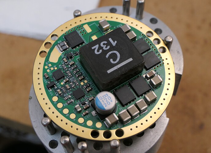
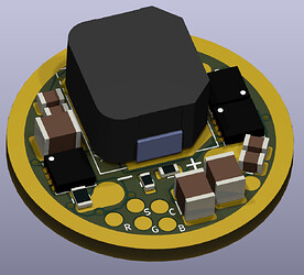
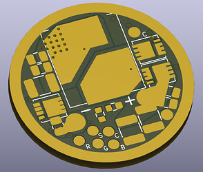
Initially I wanted to go with a dual phase controller, which means two inductors and two pairs of MOSFETS, dual phase would have allowed potentially more power and lower amount of capacitors but the available height was not enough (8mm) for suitable inductors (e.g. XAL1010, 10mm high), so I went with single phase and a XAL1580 (15x16x8mm).

I ordered the boards from JLCPCB because they had a good promo on their high end 4/6/8layer boards, which I received 2 weeks later (pretty fast!)

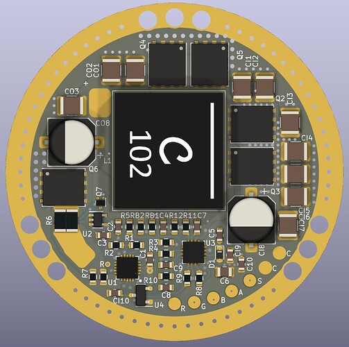
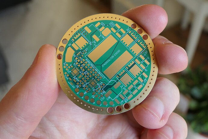
Assembled :

Testing :

For now I have only done a precise efficiency measurement at 10A because my lowest resistance curent shunt is 5mΩ 1W which is only good up to 14A.
11.764Vin, 5.811Ain, 6.903Vout (2P XHP50), 9.642Aout, efficiency=97.4%, LTPowercad simulation was 97.2%.
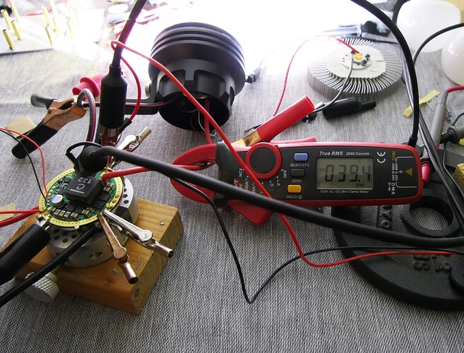
And a quick measurement with the current clamp at full power :
12.117Vin, 24.5Ain, 7.390Vout (2S4P SFT40), 39.4Aout : efficiency=98%, which again is about the same as simulated.

Next I’ll try to push it to higher output current, I need a better test load though, @haukkeli sent me XHP70.2s for that but I haven’t received them yet.
I’ll order 2 and 1mΩ precision current shunt for more accurate efficiency measurements above 14A, also I’m mising some components for low modes.
20 Thanks

Reserved

1 Thank

Excellent, Nice Machiny !

1 Thank

Good job, this would power 2S8P 1mm² osrams

1 Thank

Thanks.
Checking that everything looks fine stability wise, no problem at any output current, here’s the output and input ripple voltage at 40A :

About 70mV peak to peak for the output and 410mV for the input.

3 Thanks

Keep sharing these awesome projects. I look forward to seeing how it performs when completed with the XHP50.3 HI’s.

Efficiency, power, and both efficiency and power at the same time!

1 Thank

This looks very interesting for driving SFN55 or similar LED in a controlled way. What kind of UI is used?

It’s Anduril 2.

Unfortunately I have put aside this driver for now because after testing at 12Vin with an ATX power supply I tried at lower voltages and when reaching ~9Vin the controller would turn off at high power, after further testing I determined that it is at high duty cycle that this problem occurs, that is when Vout is close to Vin, I figure it must have to do with the charge pump circuit that power the high side FET at high duty cycle, maybe a leak somewhere… anyway after hours of testing I still couldn’t solve it so I left it there… I will revisit it later, and if I can’t get this controller to work nicely I can still go with a TI one with minor modifications.

In the meantime I continued working on a high power boost driver, initially for muli parallel cell soda can lights, that driver would also have integrated USB-C charging, but I figured I’ll do a version without charging first for single cell lights, less stuff to worry about in case of problems.

I assembled it a few days ago :

https://i.imgur.com/wjel103.jpg

https://i.imgur.com/pQerHfN.jpg

And made some measurements :

https://i.imgur.com/9J1K5yO.png

https://i.imgur.com/lclL0OS.png

It’s quite powerfull :boom::rocket:

8 Thanks

Good job it looks very chunk-y. Do you know how it compare with loneoceans gxb100 driver? I remember I read about something similar from a few years ago.

1 Thank

Chunky boy. Good job.

1 Thank

Yeah it is, I planed to put it in a Noctigon DM11, the diameter is right (30mm) but I just learned the driver cavity is only 8.1mm deep, I thoguht it was deeper than than, the inductor is 10mm :face_with_spiral_eyes:

Difficult to say because there isn’t much detail on it. It uses GaN FETs but at the time I don’t think there were very low RDSON ones available, currently the one with the lowest resistance is the EPC2066 with 1.1mΩ max, I think it’s pretty recent, although I can’t find their release date.
Using GaN FETs normally allows higher switching frequency than silicon FETs without decreasing the efficiency, this enables a smaller solution (smaller inductor, less capacitors), this is because they have lower gate charge characteristics for the same ON resistance and generate lower losses at each cycles (switching losses, driving losses), but with these very low RDSON models the difference in gate charges isn’t very large compared to the best silicon FETs available today (Infineon), GaN FETs really shine at higher voltage, like in the SMPS of USB/laptop adapters and the likes where they have significantly better gate charge characteristics than Silicon FETs.
Still, a high power GaN FET driver made today with the EPC2066 would have an edge.
It would be cool if @loneoceans could chime in and comment, but unfortunately he hasn’t been online for a while

1 Thank

Here’s a simulation example with power losses distribution :

Some of the components resistance are adjusted (increased) to take into account trace resistance and heat, notably the inductor, normally it’s a smaller proportion of the losses (but still a major one).
Here the switching frequency is 230kHz which is pretty low and was chosen for high efficiency, in consequence the switching losses (control FET ON/OFF) are very low, as well as the driving losses, the downside is that the inductor is quite massive and the amount of IN/OUT capacitance is also high. Swapping the FETs to GaN wouldn’t change much here.

Now say we crank it up to 800kHz (using a smaller inductor of lower inductance and same DCR) :

Suddenly the frequency dependent losses increase and the lower gate charge of GaN FETs (notably gate-drain charge that affect switching losses) would help, that said we can’t increase the switching frequency too much because at these low voltages the sync FET body diode generates a lot of losses, in the case of GaN FETs their equivalent body diode have very high Vf, >2V, and preferably the sync GaN FET is paired with a schotcky diode to prevent high diode losses during dead time (when both FETs are OFF), we can see it on GXB100 and it’s nearly as large as the FETs which is something to take into account when trying to reduce the solution size.
So yeah, lot’s of stuff to take into account with trade offs that’s why I mentioned it’s difficult to say :grin: , in any case, a GaN FET driver is super neat.

Regarding the trace resistance losses, they are actually are a non negligible part, because I was cheap and used 1oz copper weight (thickness of the copper, 1oz=35um), a high power driver driver such as this would at least use 2oZ, I did add a copper strip between the indutor and FETs. In a smaller version version I’m working on I removed the mask in a few critical area for adding copper strips/solder tracks.

4 Thanks

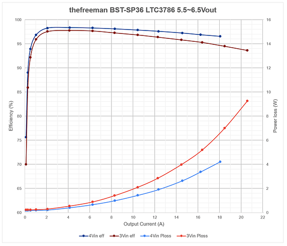
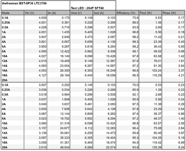
I did some tests at 12Vout, with 1S and 2S input :

I couldn’t do all measurements due to power supply limitation, the Vf of 2XHP70.2 with shunt and wire was too high and I didn’t have enough power for 2S in 15Aout at more than 15Vout.
As expected the efficiency is lower at 1S to 12Vout

3 Thanks

Good job as usual!

1 Thank

:scream: Oh my goodness… serious numbers here!

1 Thank

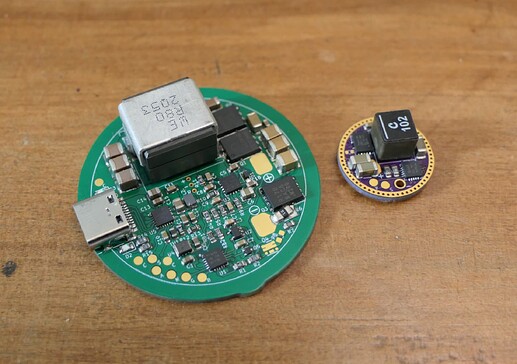
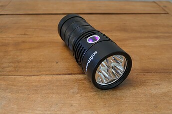
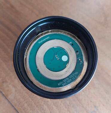
SP36 ~130W boost driver (next to a 17mm driver), with USB charging :

It uses the same boost controller as the single cell driver above, with larger FETs and better inductor (only 0.420mΩ !) for more power/efficiency.


I couldn’t test 20A at 4Vin with my power supply, for 3Vin at high current I used two A123 20Ah LiFePo4 cells.

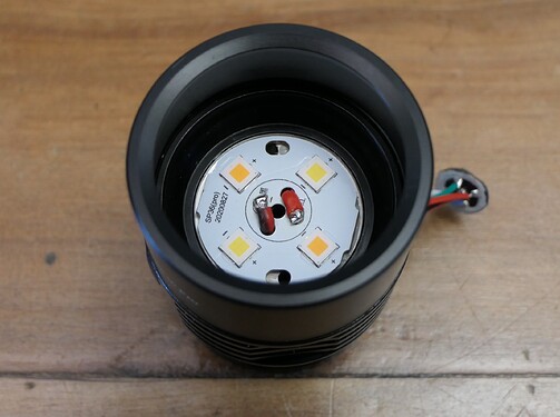
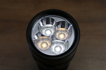
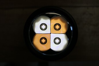
I used 2700K and 5700K XHP50.3 HI 90CRI :

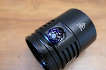
I replaced the switch with a longer travel, quieter one, I had a switch PCB+RGB from another mod that roughly fits :

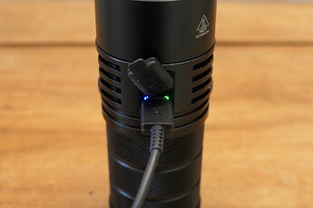
Originally the switch red+green LEDs served as charging indicator, but since I put Anduril RGB there I aded LEDs visible through the USB port gaps :

So as expected it’s very bright, I haven’t measured the original current with the SST-40 but considering the LH351D version draws ~16A with sofirn cells, I’m guesstimating 25A max with SST-40 and good cells, about 85W, with my boost driver I get about 50% more power, altgough being high CRI and neutral white once mixed it might not be much brighter, of course being a boost driver it can deliver full power until the cell are depleted whereas at half SOC the original direct drive driver only allows a little more than half the current.

It’s also quite throwy, unfortunately there is a small blue spot in the middle of the main spot that is quite jarring, the reflector being smooth I feared something like that might happen, @Haukkeli said that it could be bad focussing and indeed the reflector is quite high above the LEDs, even without the centering gaskets the actual reflector part starts ~1mm above the LEDs, maybe even a bit more, not sure yet what I’ll do about this, an OP reflector would be ideal of course.

Regarding USB charging, I misread the datasheet and thought it could take advantage of higher voltage adapter (9V1.66A) from Samsung/apple to charge at 15W, bjt nope, only 5V2A, which after losses in the cable and charger is more like 9W charging.
It also support USB OTG with 1.5A reverse boost, although I haven’t tested that yet.

12 Thanks

Good job!

1 Thank

The blue spot in the center of the hotspot is a XHP50.2 and XHP50.3 signature, mine has it too (6500K XHP50.3 HD). Playing with reflector height may result in a less noticeable or non existent blue spot, but some intensity may be lost.
Just being able to use these LEDs is awesome enough i wouldn’t even mind the spot or the intensity loss :slightly_smiling_face:.

1 Thank

Awesome job and I want switch and driver. How did you upgrade the firmware?

1 Thank

Flashing pads, I use the T1616 in all my drivers.

ok, first time seeing it, but previously I only used them with OP reflectors. Outside it’s not really visible unless pointing the light at a wall of ground.

1 Thank