My measured lengths are 8mm and 4mm...
I, uh, think I did my test wrong. I tested spring travel in the tail switch from the top of the tail cap.
I see now, after reading that a few times, that you want a reading on the body itself, with the battery pressed into the driver spring as one reading from the end of the battery tube, and resting on the driver spring, as the second reading.
Sorry. I’m a dum bass. In my M8, as it’s currently set up, those numbers are 5 and 9.
:8) <—- supposed to be an embarassed smiley, doesn’t work for whatever reason, much like me.
a GB would e nice on those
I'd be in for a group buy for sure. I'd want hundreds.
I just noticed he's selling them in quantities of 1-10 at $6 each...buying in lots of 100 direct from the manufacturer is $1.50 a piece! Hell; if purchased in lot's of 1000 they comes down to $0.53 cents each.
EDIT: Because I have a big interest in these springs I'd be willing to organise the GB. However being located in Australia it does not make me the best person to receive and split the shipping up. We need someone stateside I'd say.
i wondering once the GB is done u can have the manufacturer do a split order ? one to u and someone in the US ?
Would I regret it if I said I could do that? I’d want 50 or so myself, could probably handle shipping em out to the group buy participants. Wouldn’t want it to be costing me money that got me in trouble with the wife, lol.
I'd start by creating a new thread to gauge interest. That way we'd find out how many looking at ordering. When we have a good idea as to how many we're after we can email Lee Spring Co. and request a quote. Once we know what the prices will be we get people to send money for their springs plus shipping (packing material and shipping costs).
I'd chuck in a few bucks extra to cover your efforts in splitting them up and shipping them off. Hopefully Lee Spring Co. would be kind enough to bag them in lots of 10 or so lol...
I could separate them into the groups needed, bag and tag em, ship em out. I’ve probably got more time than most anyway. I’d say go for it.
Sounds great I’d be in for 40pcs if we get them down to $ .53
Guys - Re springs, please start another thread and talk about it there otherwise it can confuse/derail this thread.
Guys - Re springs, please start another thread and talk about it there otherwise it can confuse/derail this thread.
it’s already de-railed.
Being as how Matt and Tofty are working together on this switch as well as another, the spring issue is relevant…or so it would seem to me and it was, in fact, merely a suggestion to aid the switch in output.
But yes, of course, research and interest would be done elsewhere. Thanks Norm, for your interest and guidance. ![]()
It doesn't exist yet. As far as I know.
Check recent posts.
Right well back on track with the promised information regarding the dismantling and re-assembly of the switch.
The only tools that you will absolutely need are two sewing pins, with a diameter of 0.65mm or there abouts.

To disassemble; start with this.
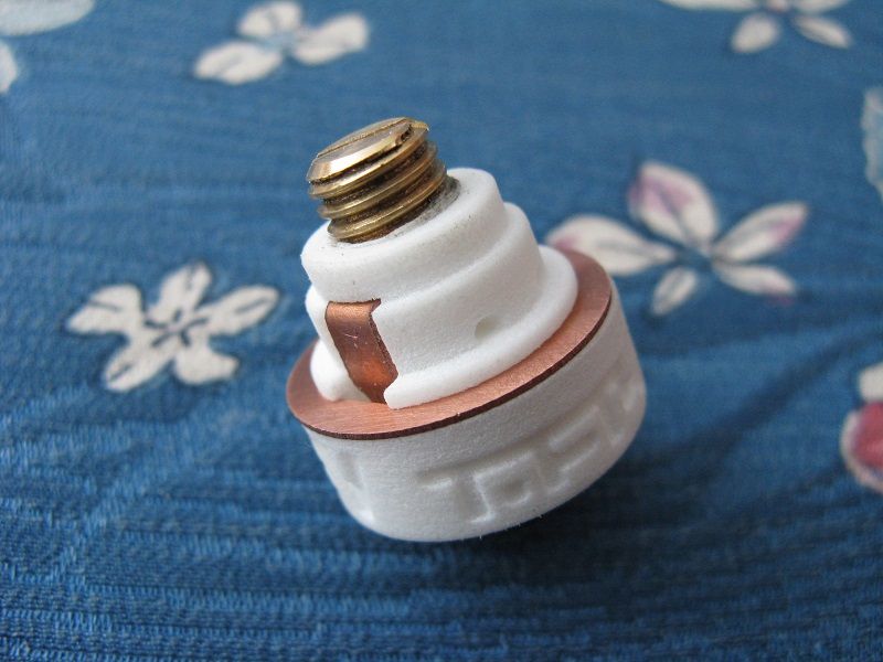
Remove the brass grub/set screw to allow the corresponding copper lead to be removed later.

Unscrew the two plastic sections to expose these components.

Remove the remaining copper lead.

To reassemble, compress the central copper plunger and spring to it's limit and insert the two pins to secure the plunger in place. This isn't all that easy so be careful not to let the spring go pinging off anywhere.

Reinsert the two copper leads into position.

Screw the two plastic halves together again. When removing the two pins it is a good idea to compress the switch button to avoid the central plunger hitting the two lead faces with force and potentially bending them.

In relation to the central brass screw or piece of threaded rod it is important to have a clean and unburred start to the thread to ensure that cross threading does not occur as this will do a lot of damage to the plastic thread. I managed to damage two of my plastic hosts this way, however it is much less likely to happen after the hole has been successfully screwed into before. The problems i had were a poor start to the thread, an over-exaggerated chamfer on the screw's end and the overly tight threaded hole in the plastic host. The first two problems can be solved by the correct finishing of the screw's end after cutting it to length and the last problem is solved by screwing into the hole for the first time, which compresses the slightly fuzzy plastic edges, widening the hole somewhat.
Great design! Genius in fact! A bit off-topic but: If increased amperage were not the main goal but a shorter length switch instead, is there anyway to make a shorter switch so the total length of the light can be reduced?
The idea is to use an 18650 battery, an 18500 tube from OR or FM, and a shorter switch/slightly longer tailcap, for a shorter overall light. Thanks.
Edit: Now that I’ve read the thread a bit more, seems the shorter and more compact switches have the main current going through the spring - not good for reliability and higher resistance.
PM Sent.
Thanks, i'll do a drawing in a bit showing the switches internal layout in terms of height so you can see which bits take up the space. As you mentioned in your edit; trying to remove too much height can lead to some pretty lousy compromises.
Just an advisory to the beta testers, please do a test fit of the switch into your chosen tailcap without the rubber boot installed, just in case it's a bit too tight and needs to be forced back out.
Here is a drawing showing the internals of the switch and how they stack on each other.

The red and orange parts at the bottom are the switch button and the rotating latch,
The yellow parts are the copper plunger, shown at it's limits and in the off latch position,
The green parts are the 0.5mm thick copper leads,
The blue parts are the body shell,
The orange part on top i the screw in contact post which replaces a contact spring for this switch.
(the internal spring is not shown but sits inside the copper plunger)
As you can see the clicky latching mechanism takes up a great deal of room and although perhaps 5mm could be squeezed out of the overall height in various ways it would weaken the switch and reduce it's robust function.
Some kind of electronic switch is the best way to reduce switch height as it doesn't need a latching system but will must likely have the 'always on' power drain problems i personally like to avoid.
Interesting diagram! I was trying to figure out how to make a mechanical latching system using a cam-style design which would latch outward (in the radial direction) toward the side (to reduce axial length) but I guess we are talking about such a small space in all directions!
Spark Flashlights (Zebralight?) made an electronic tail switch at one time but I don’t know how well it worked.
Your switch is 22mm long - how does this compare to a McClicky if the spring is compressed to minimum length?