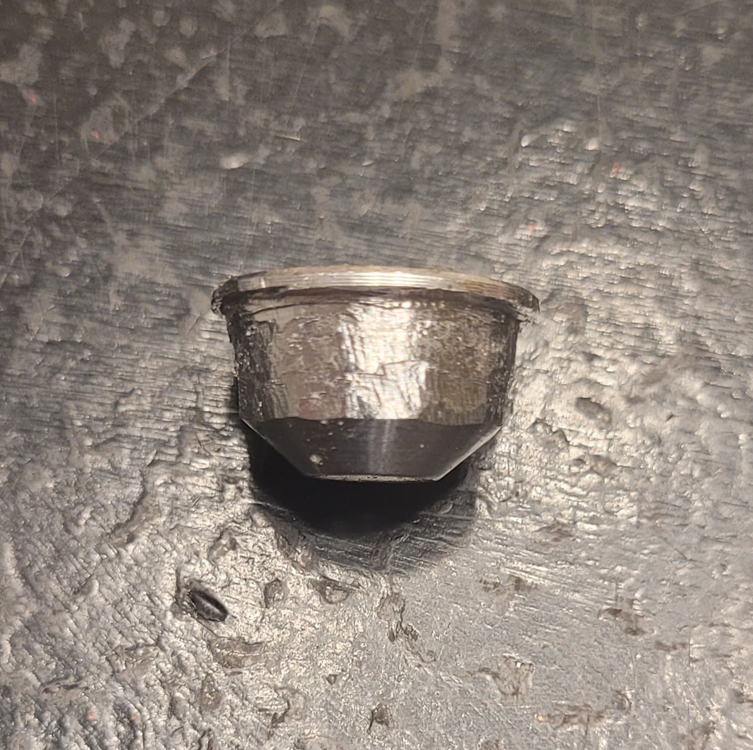
Oven cleaner might be easy to use than lye. You just spray soak the light in a container, for a few minutes. I didn’t have to disassemble and patterns making kind of works with masking tape.
Partially removed anodizing on the left (scuff marks unrelated)
The Bezel, Battery Tube, Clip, Clip Oring, 0603 Ice Blue LEDs and Driver Retaining Ring were given to me for free at different times by a friend of mine.
The Head I found via the Buy/Sell Thread and was also free!
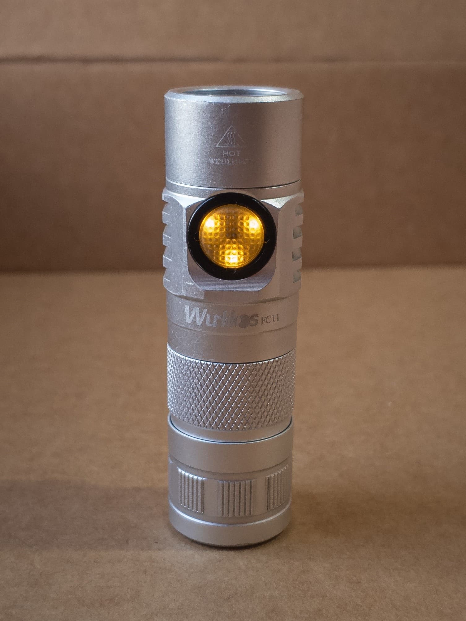
I did it again, another victim of the caustic attack, this FC11 was a little worn out, so i decided to strip it completely. The dings and scratches disappeared and the light looks new again.
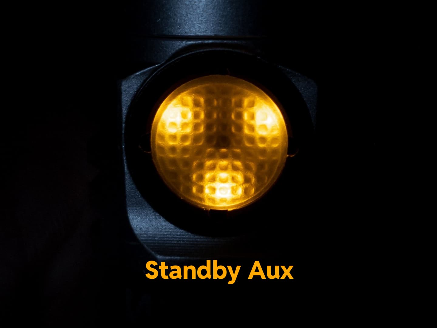
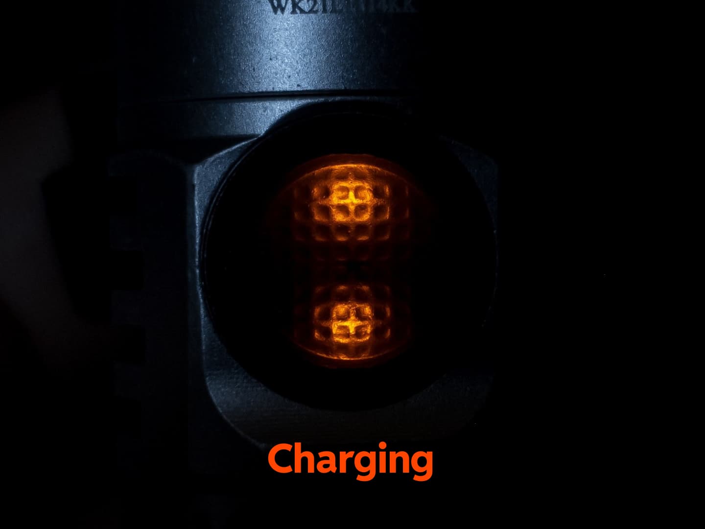
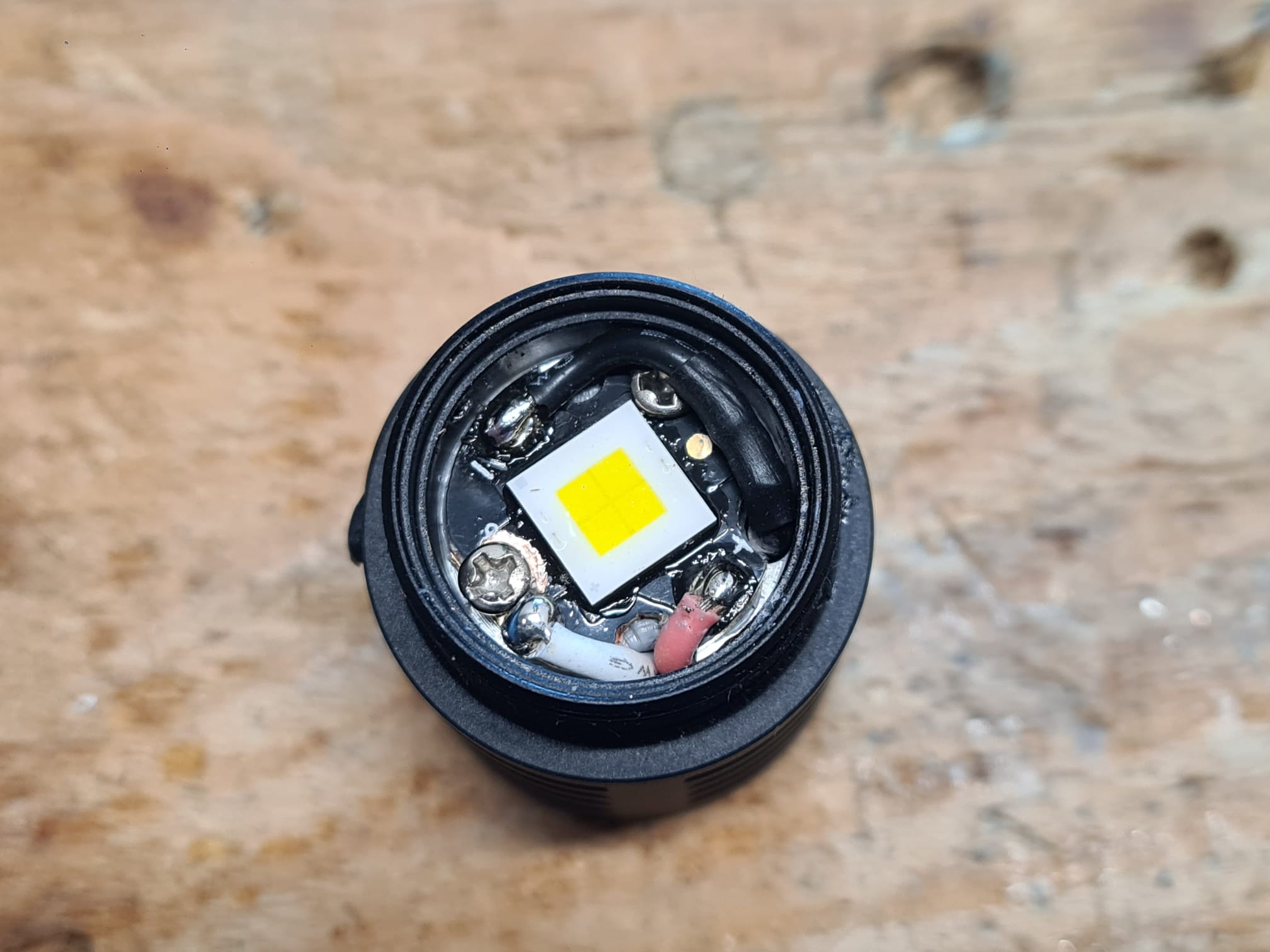
LED was swapped for a 6500K 95 CRI Yinding round LED, and the switch LEDs were also swapped, PC yellow for the standby aux and amber for the charging indicator. It was already using the SC31 Pro driver.
The nice thing about PC yellow LEDs is that they are brighter than direct emission amber and they behave nicely at low brightness (direct emission amber gets so dim it looks like it’s turned off).
Just before I went the caustic route (would have if I had any) decided to try to redo the tube again over an open hob flame but for much longer. Took a bit of time but I’m ok with the final result. Also took a bit of fine grit sandpaper to the bezel for a slightly shiny chromed brushed effect. Think that’ll do for now as any more and it knacker it again.
I try to make a phone pics today…or tonight. Yes,its stock driver and new xhp 16mm from kaidomain.Nothing else.Its a wall of light i have to say.Dont want to imagine concidental work mode in my pants…Its HOT after seconds.But its worthy for me:))
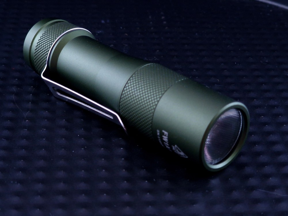
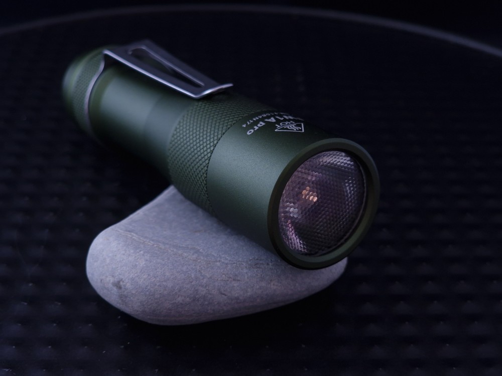
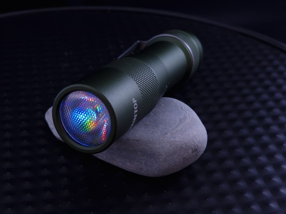
Having done my first FW1A mod two weeks ago and still having an SFT40 left over, I wanted to repeat the mod with a different coloured host - this time a green FW1A host.
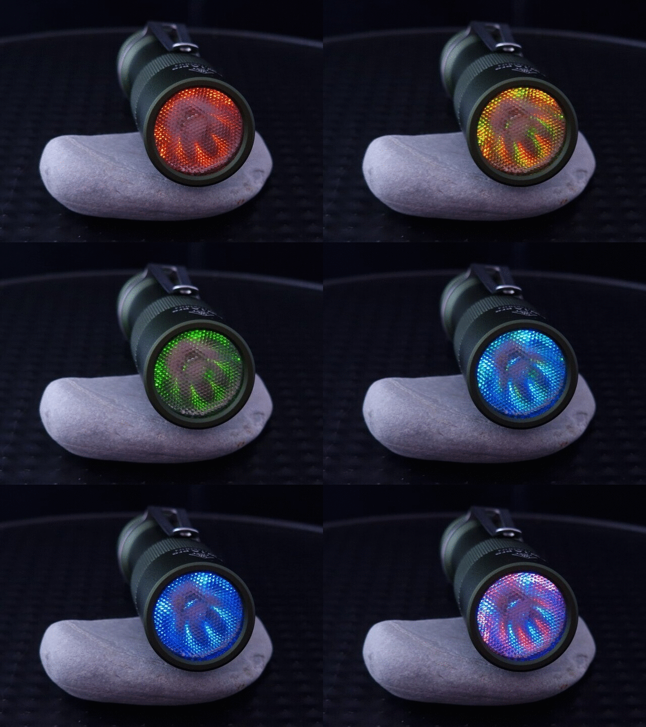
Other than the host colour, the only other difference between the two mods is that the green one has orange, yellow/green and ice-blue AUX LEDs, instead of the orange, purple and ice-blue AUX LEDs in the grey host. The yellow/green goes nicely with the green host.
For some reason, which I haven’t diagnosed yet, the FET on this driver isn’t working. Must be a bad solder join on the adapter board. I didn’t want to take everything apart again to fix it, but I’m not happy with this. I’ll have to fix it one day.
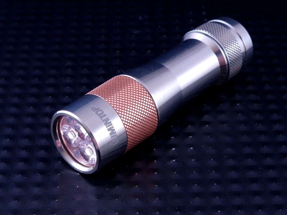
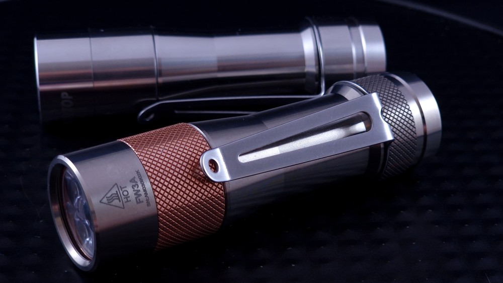
After my FW1A mod this weekend, I wasn’t ready to stop and went ahead with another FW3A mod. This time a TiCu FW3A I acquired recently.
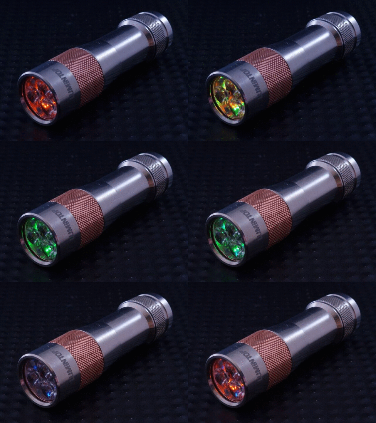
This one got a lume1 transplant, 4000K 519As in place of the 6500K XPL-L HIs it came with, and a Tri-LED AUX board with orange, green and ice-blue LEDs. Unfortunately, the ice-blue LEDs are quite dim with the lowest-value resistors I had (120Ω) so I’ll be getting some lower-value resistors to fix this.
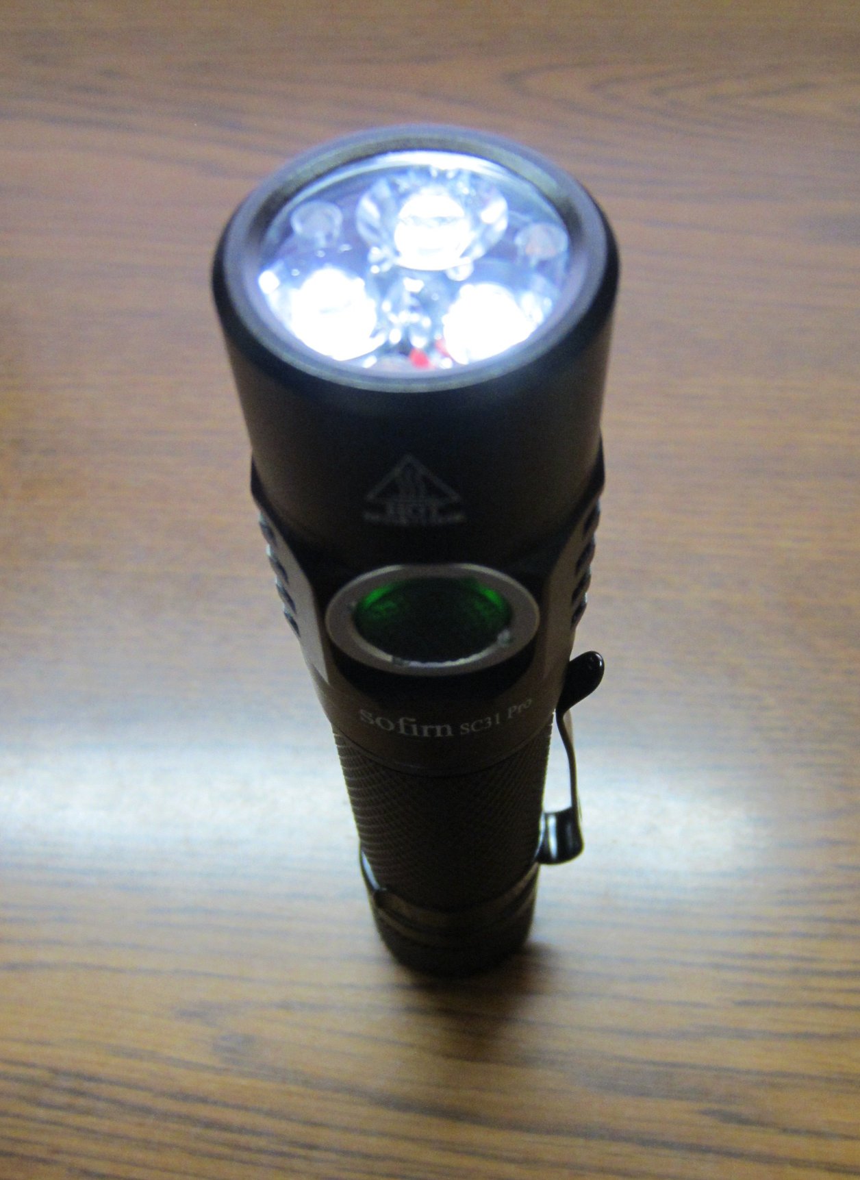
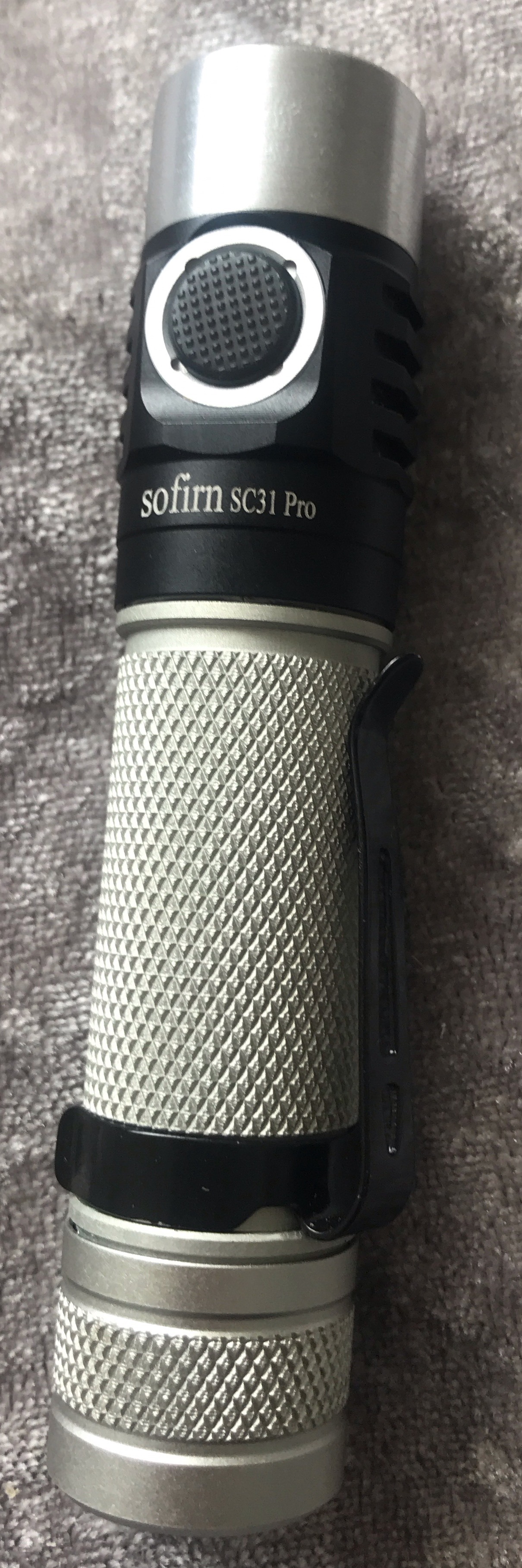
Converted my SC31 Pro to triple 519A 5000k. I Machined a copper spacer and trimmed a 20mm triple MCPCB down to 18mm. Drilled a hole through the shelf. Swapped the stock window for a KD 20x1mm AR window.
Mod in-progress. Here’s how I removed the HD10 bezel:
I slipped the head of a small nail under the bezel (I had to grind the head of this nail thinner to fit). It just pushes against the oring and should slide under there. I lined it up over one of the optic posts so as to not scratch an important part of the optic. Then, leverage the nail toward the center of the optic. I used piers for a better grip on the nail.
As with any press-fit bezel removal, do a little at a time, moving frequently, so you don’t bend the bezel. I scratched the optic a bit from prior attempts at removal. The scratches aren’t a big deal but I may try to buff them out. The nail in the pic is bent from leveraging it. That bezel was really stuck in there!
Next, I will attempt an emitter swap with hot air on the face of the MCPCB. I’ve never done this so I’m a little worried. The goal is to put some E17/E21 (I forget which I have) in there.
Edit: Emitter swap a success! First, I failed at reflowing on the face of the MCPCB. I had to remove the board. @ebastler 's review and teardown gave me the confidence to continue. I used de-soldering braid to remove the solder on the board. It’s not necessary to remove the switch.
The reflow was easy enough (maybe I got lucky though). For some reason I decided to keep one of the stock 4000K LEDs, and I installed two e17a, a 2700K and a 4500K. I figured I could save a few bucks and keep using one of the stock LEDs, while still getting a good result from the two Nichias. I should have figured out how to test the mix without needing to re-solder everything - I’m not sure I’m happy with the tint.
I think the design with the driver, MCPCB, etc. is pretty neat. Unfortunately, it’s a little time-consuming to mod but not too difficult.
Here’s a pic with the three different LEDs (stock on bottom, Nichia e17a 2700K top-left, 4500K top-right). I put DC Fix on the optic. I think it makes a slight tint improvement and a little extra flood is nice (plus it hides the scratches). The pic is a little weird I think due to the PWM interfering with my phone’s camera.


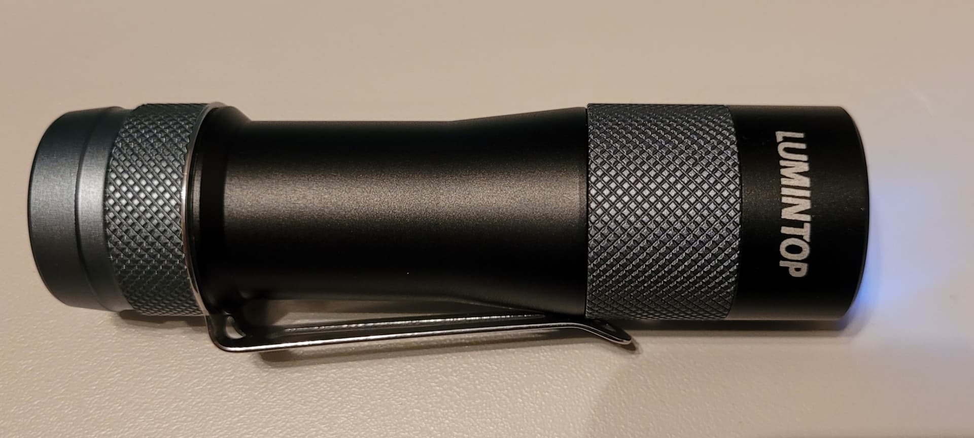
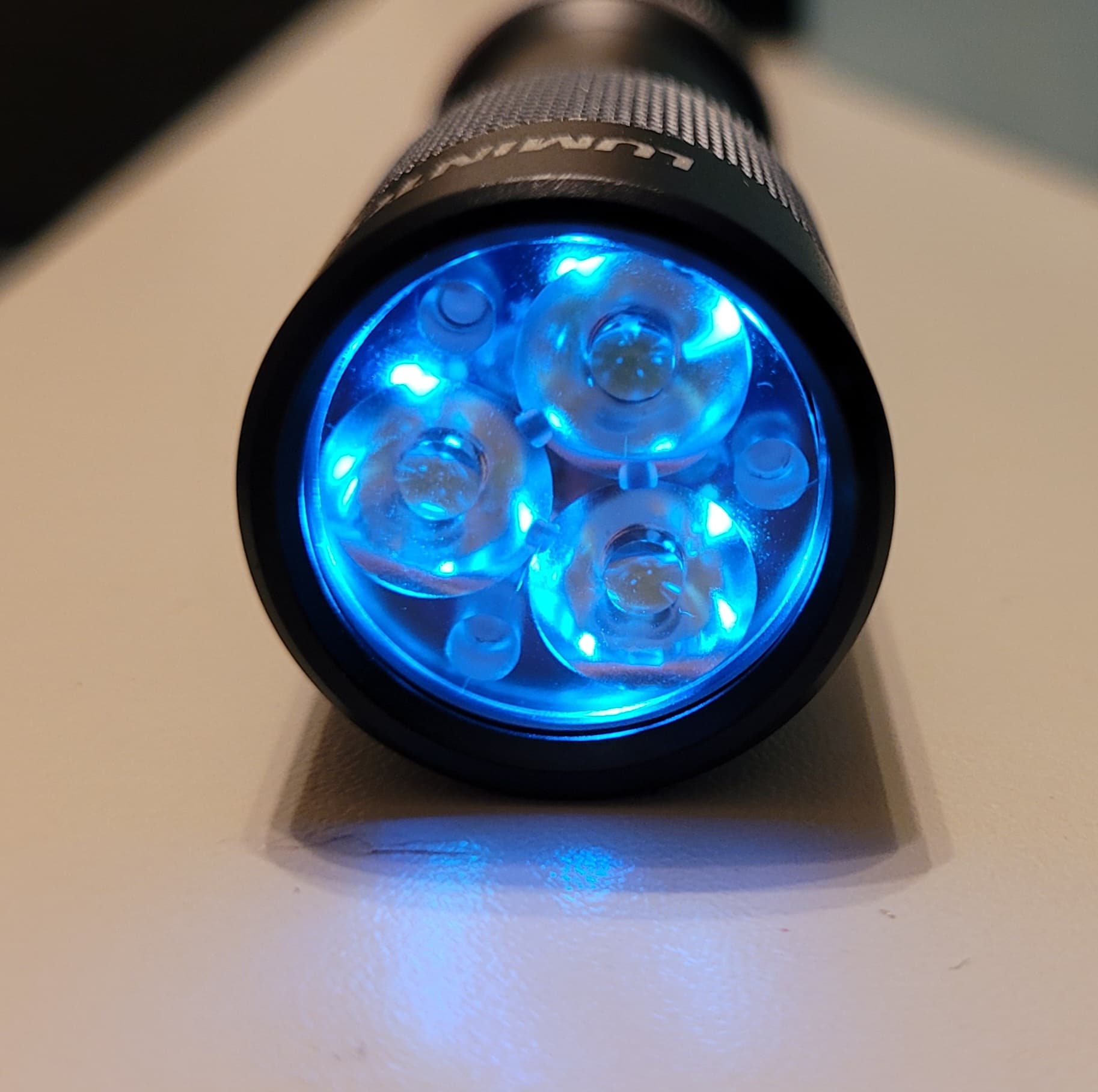

 Yes,its stock driver and new xhp 16mm from kaidomain.Nothing else.Its a wall of light i have to say.Dont want to imagine concidental work mode in my pants…Its HOT after seconds.But its worthy for me:))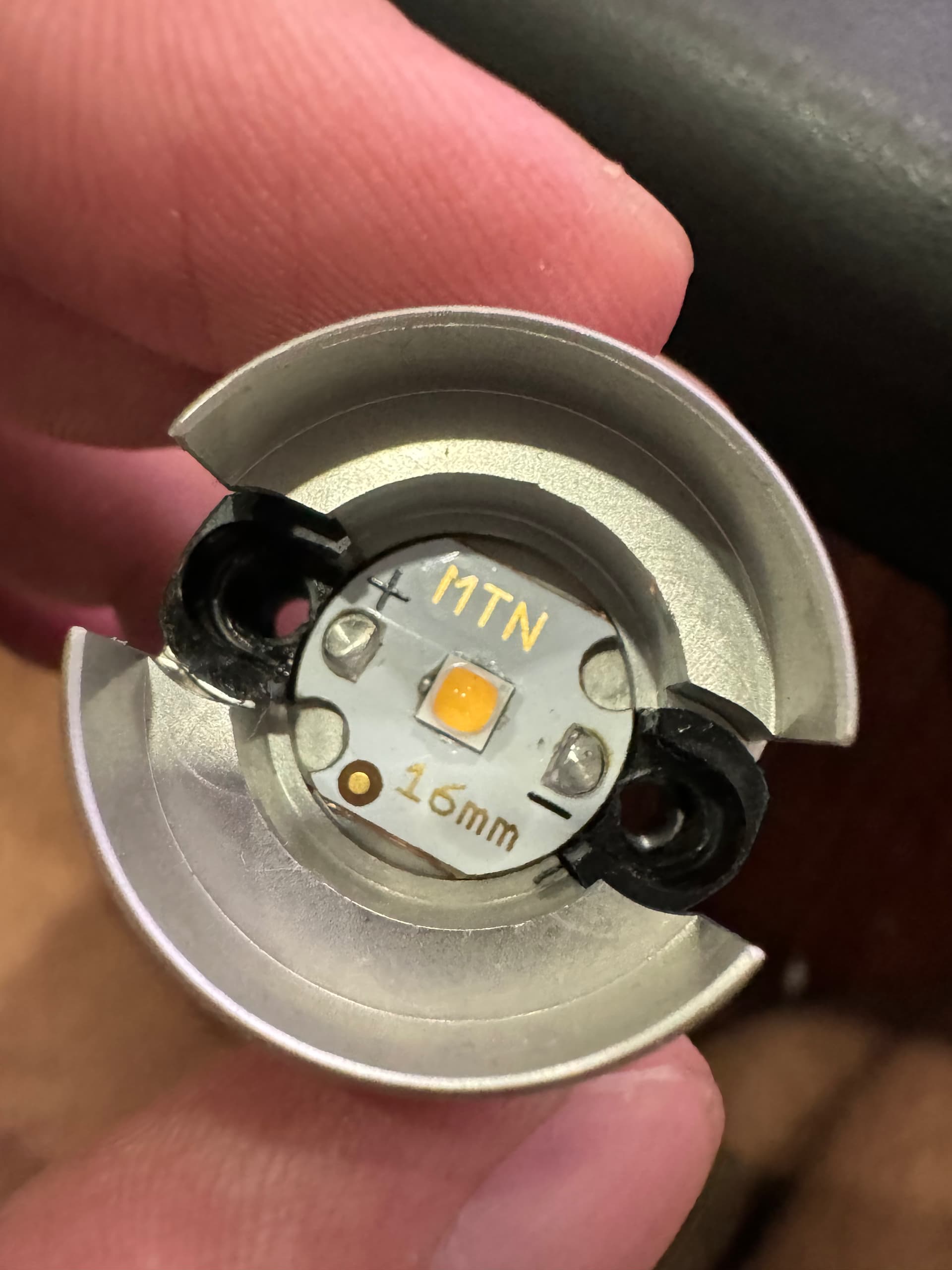

 with the FW** mods!