A little Traveling music, if you please
You may have seen the review of this light and I really like it, but I just can't leave it alone.

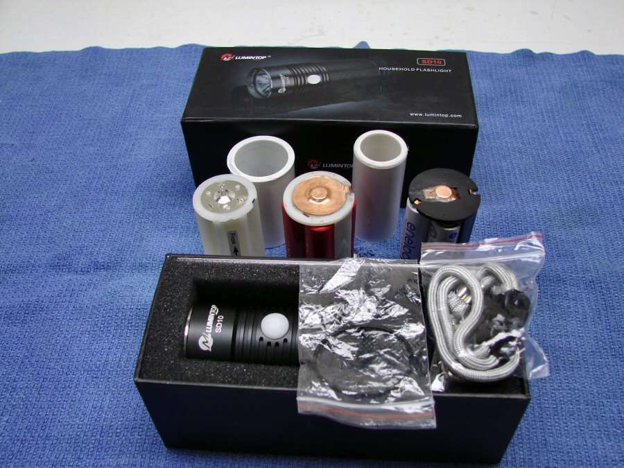
Here's how the guts came apart and then I will tell you what I want to do with it.
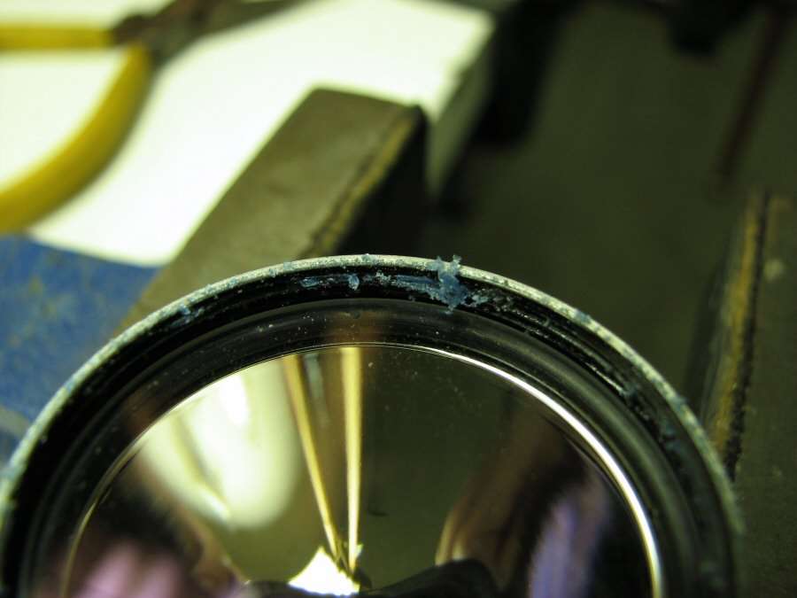
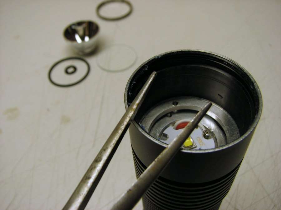
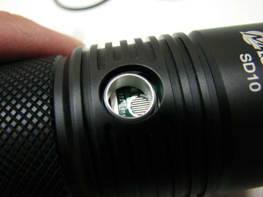
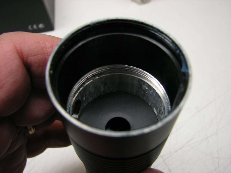
The first problem was to get the bezel off the light. It did not want to come off and when I finally got it off, I found out why. The threads are full of Blue Silicone. It's not Lock-tite and I'm glad it wasn't. I put the body in a vise and I used a pair of needle nosed pliers to twist the bezel off, by grabbing on with the slots in the bezel and Very Carefully turning it. I had to use a lot of pressure pulling the jaws open, so they would not slip out of the slots, but I did get it off with no heat. I didn't want to use heat, because I knew it would ruin the switch cover.
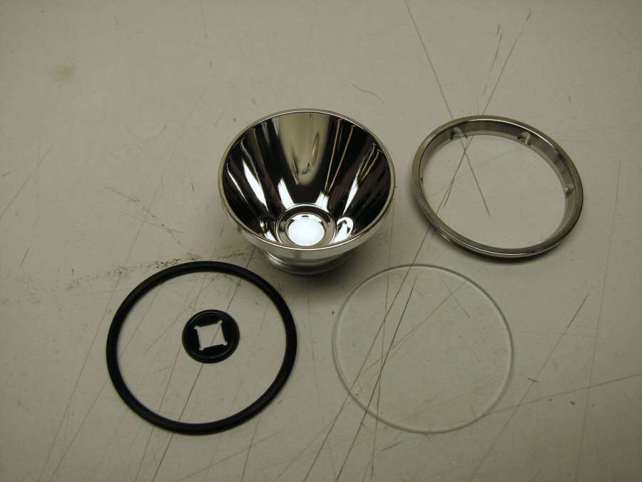
So, with the bezel off, the Lens, O-ring, Reflector and the led centering ring came out the front.
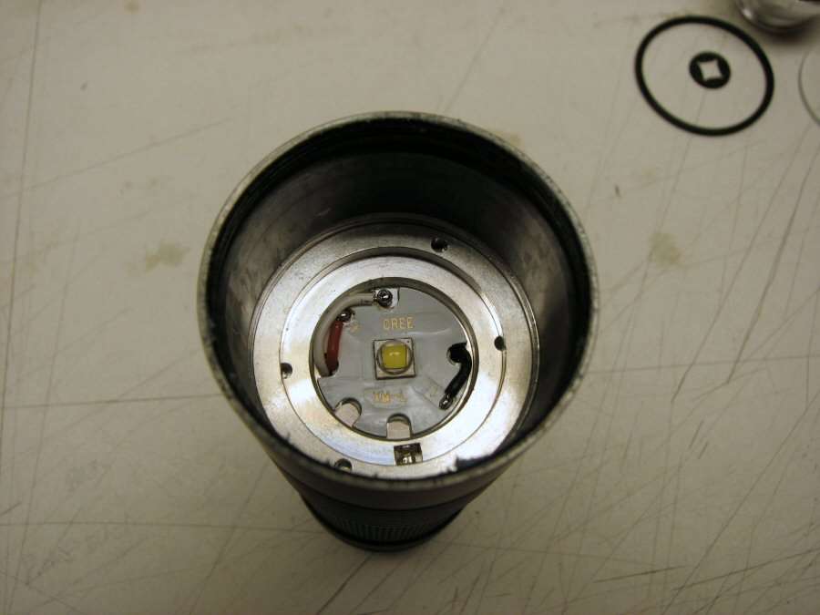
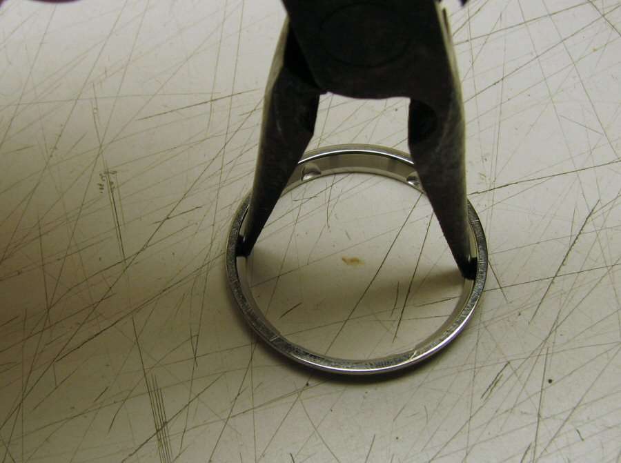
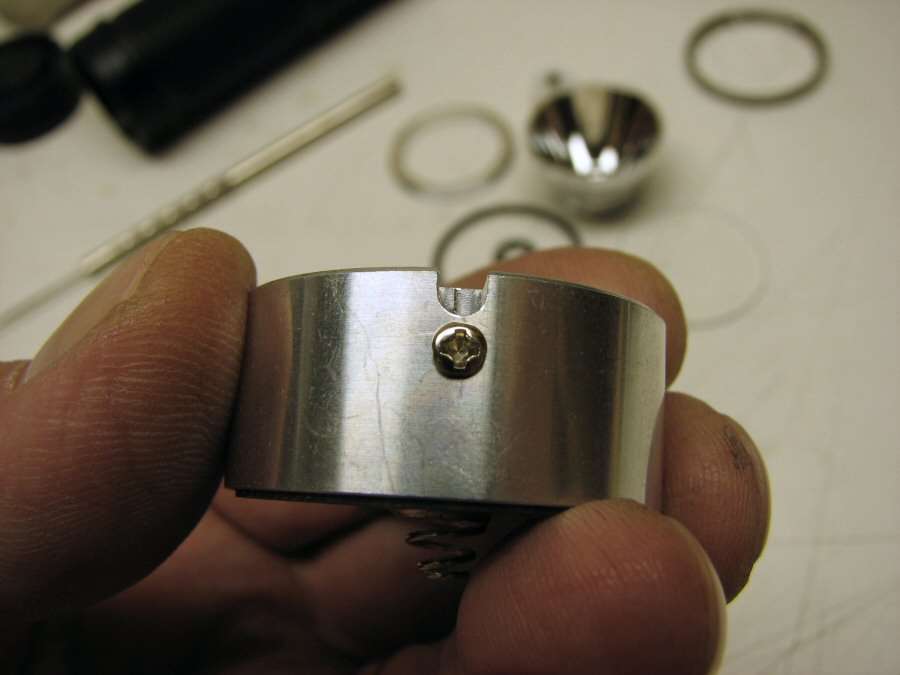
What's left inside is a retaining ring and the pill underneath it. The ring is threaded in, so I had to use a different pair of Pliers to get it out of there.
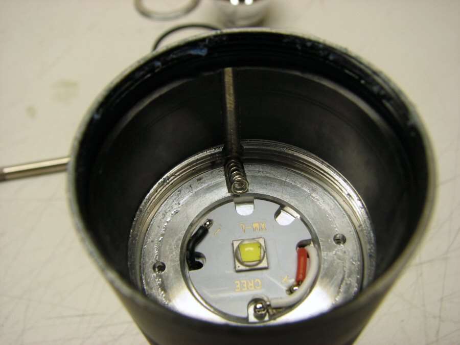
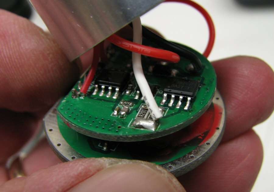
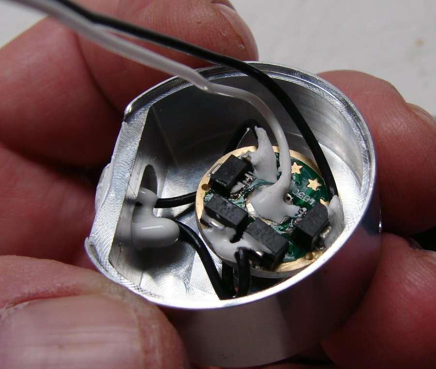
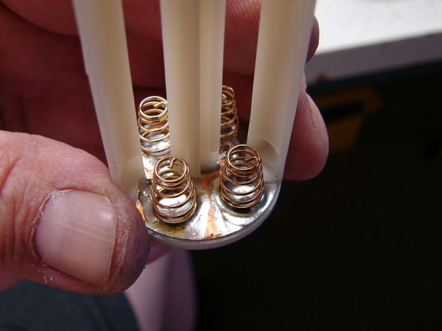
Once the ring was gone, I could see the pill. You can see there is a small spring in there. It is used to keep the pill from shifting when the retainer is tightened down. Also notice that there are three wires on top. Two go to the led and the white one is grounded to the pill. Hmmmmm.
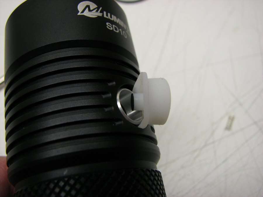
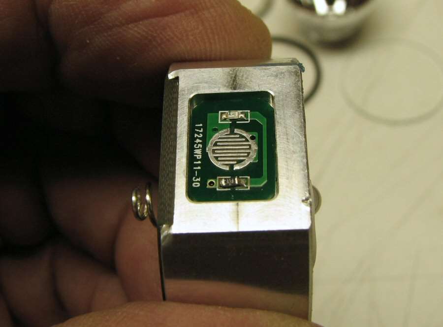
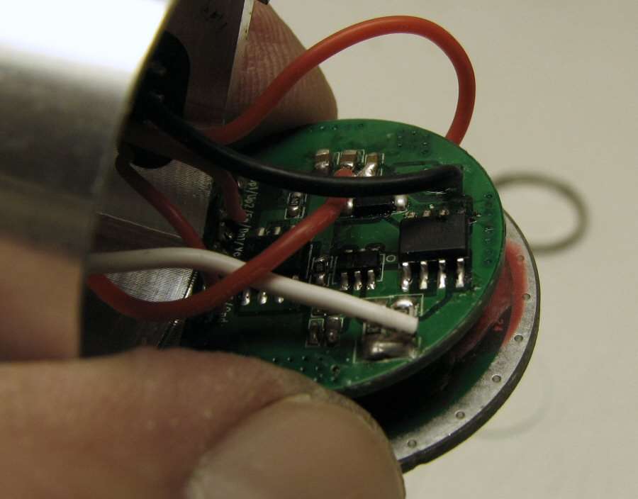
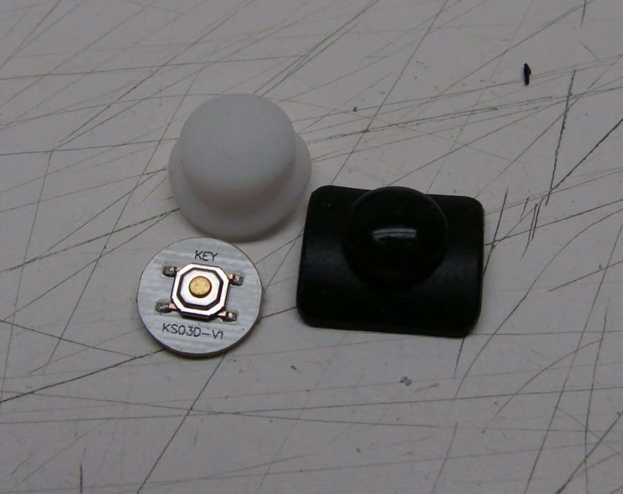
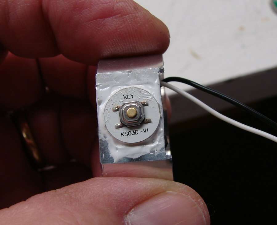
In order to get the pill out, I had to get the switch cover off and the only way I could see, was to pull it up and out of the socket. I just pinched it and worked it out carefully, in order to not rip it. Notice the black center there. That is carbon and it touches the switch, to make contact.
Here's the cover out of the way. There's an aluminum locater ring and you can see the board for the switch.
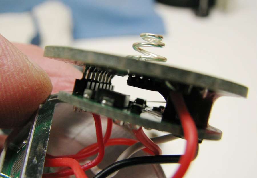
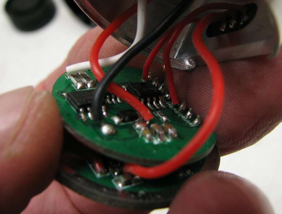
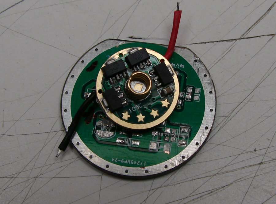
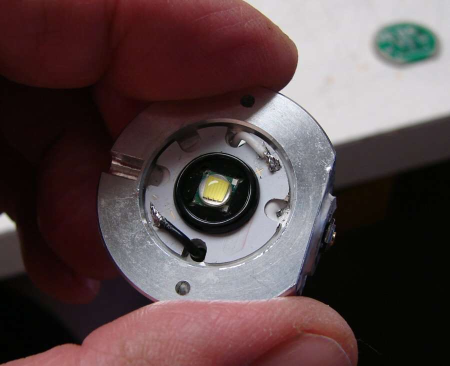
Here's some photos of the pill
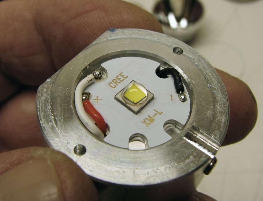
That screw has to be removed before the driver will come out of the pill.
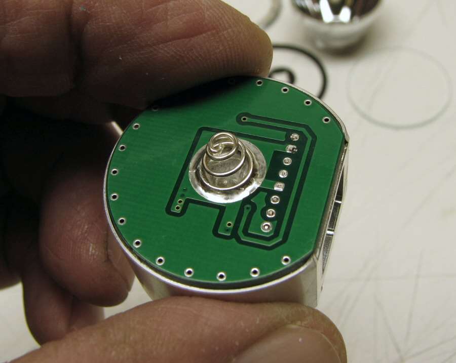
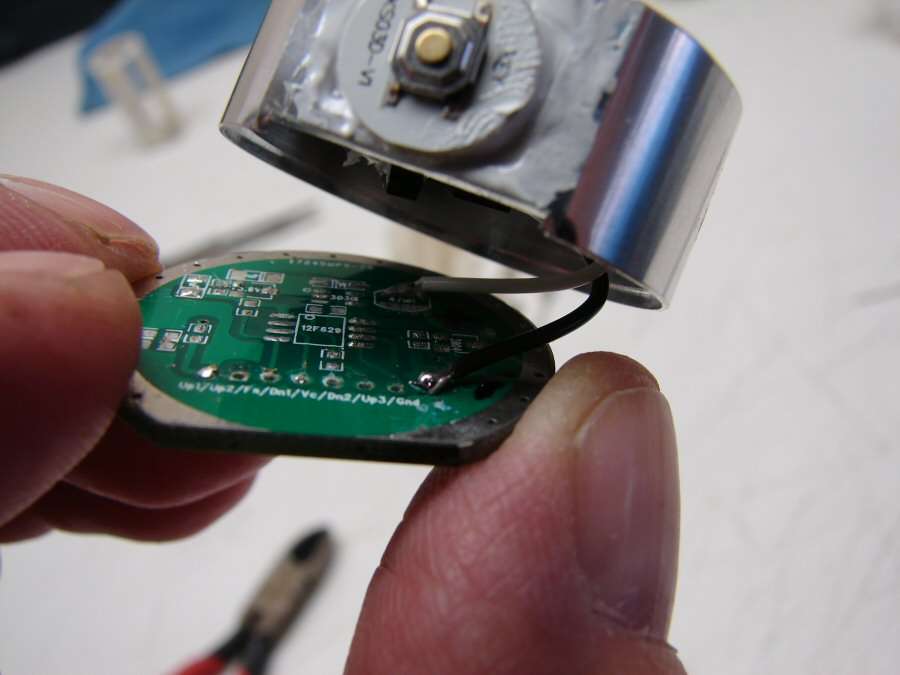
Here's the best I can do with Driver photos. I don't want to tear it apart... Yet...
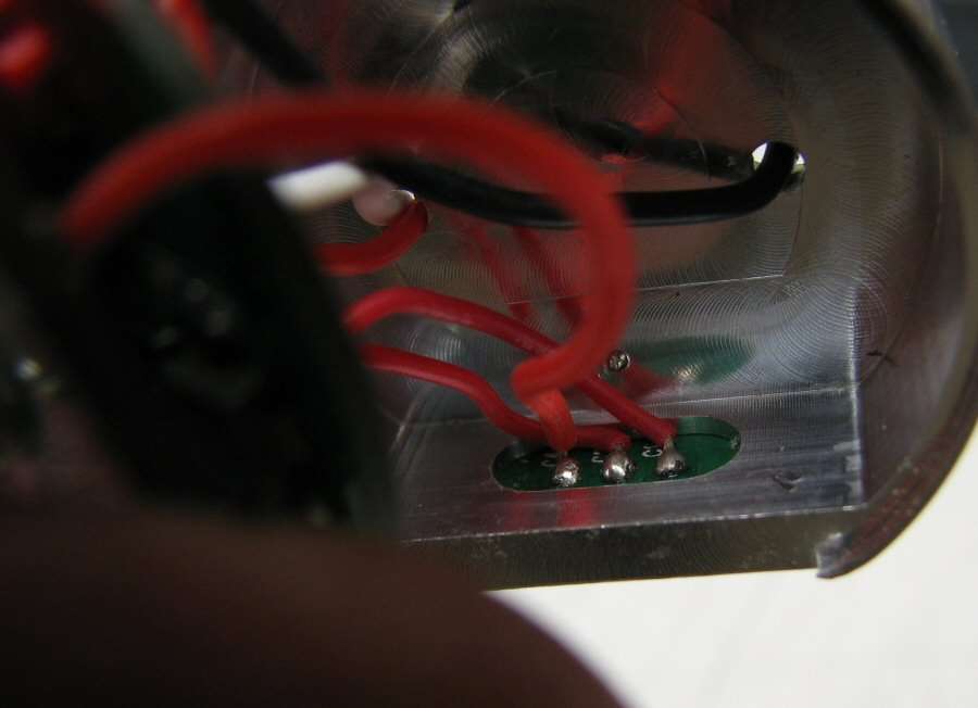
The last photo is what is left in the body, which is just an isolator plate, so that the battery only touches the center spring.
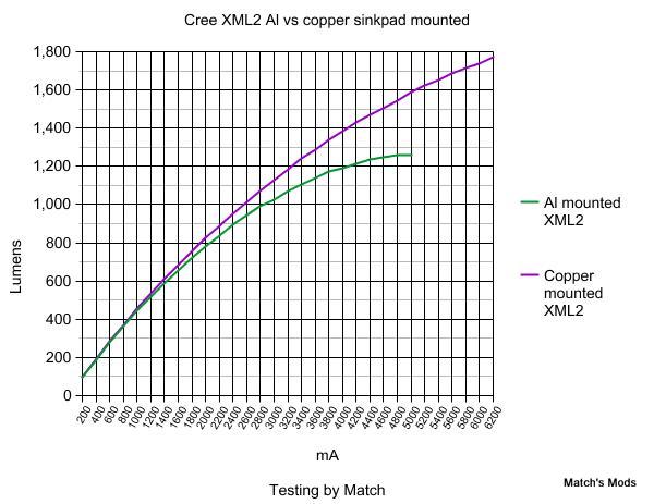
I don't care about the driver, as I will be using a NANJG (DrJones) driver to replace it, with an SMD switch to replace that. I will add chips to bring it to about 4 amps. I have a copper star to use and I will re flow the XM-L2 onto it, after I de-dome the derned thing. Hopefully it will come out with higher numbers for all the different battery configurations once I'm done.
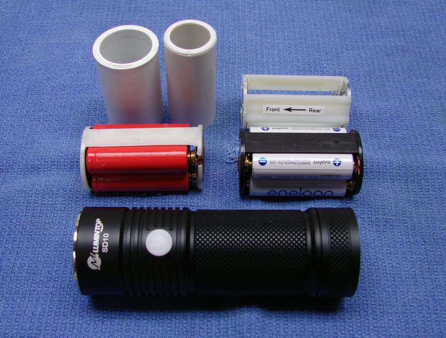
I will also rework battery holders. I will end up with the following:
a Sleeve for an 18650
A sleeve for a 26650
A 3xAA series holder
A 4xAA series holder
A 4x14500 Parallel holder
That ought to keep someone busy playing with all those different batteries.
10-10-13
Buuurrrp!
Excuse me, I got gas.
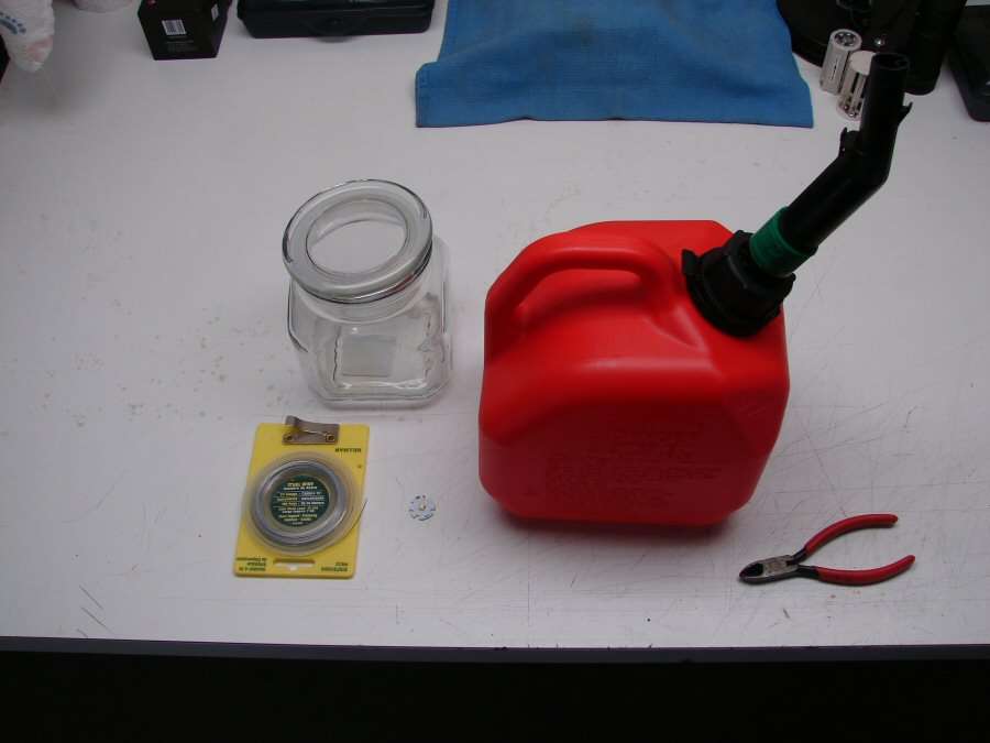
Yep, I went and got a gas can and a glass jar, so I could do the infamous Gasoline De-Dome.
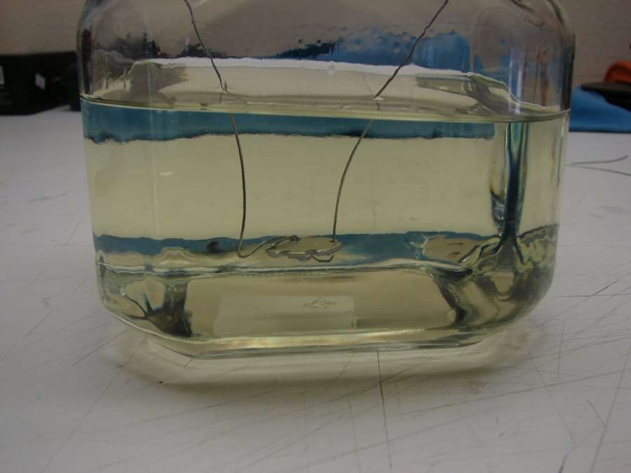
I wrapped a litle wire around one side of the star and hung the XM-L2 upside down into the gas. Time will tell... Approximately 24 hours or so?
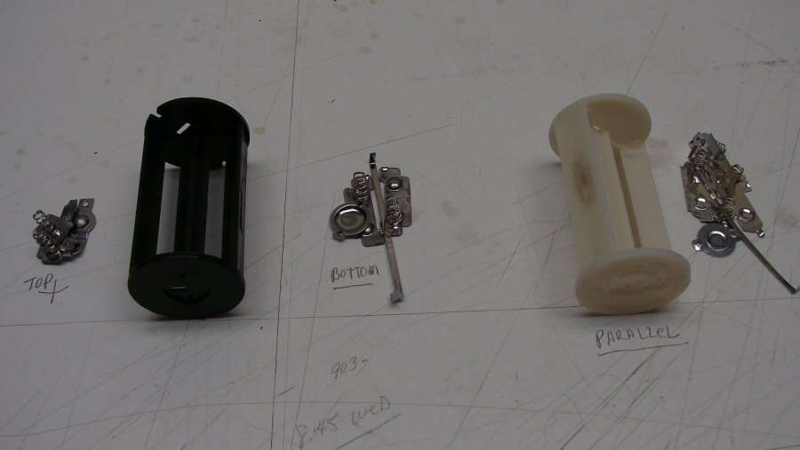
I have stripped down two holders for AA/14500. One will be done in series, with copper and the other will be done in Parallel, with copper.
I'm not even going to touch the stock 3AA holder. 3AA isn't going to get it with a 4 amp driver. The voltage will drop too fast and the amperage will never be seen. I will stick to 4AA in series and 4x14500 in parallel for the holders.
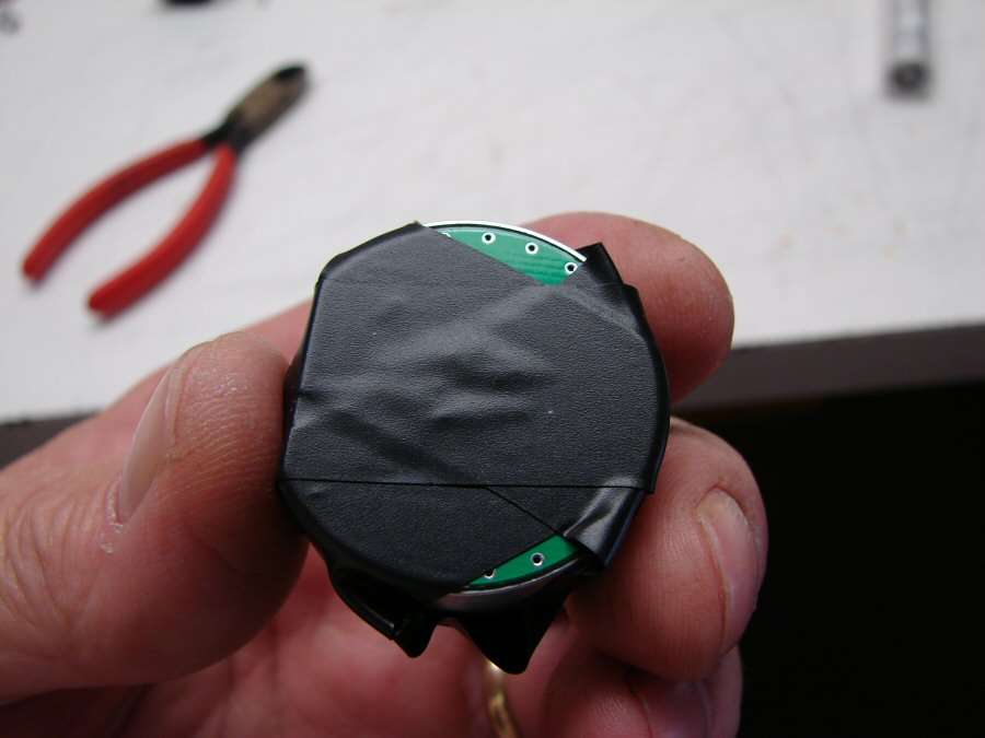
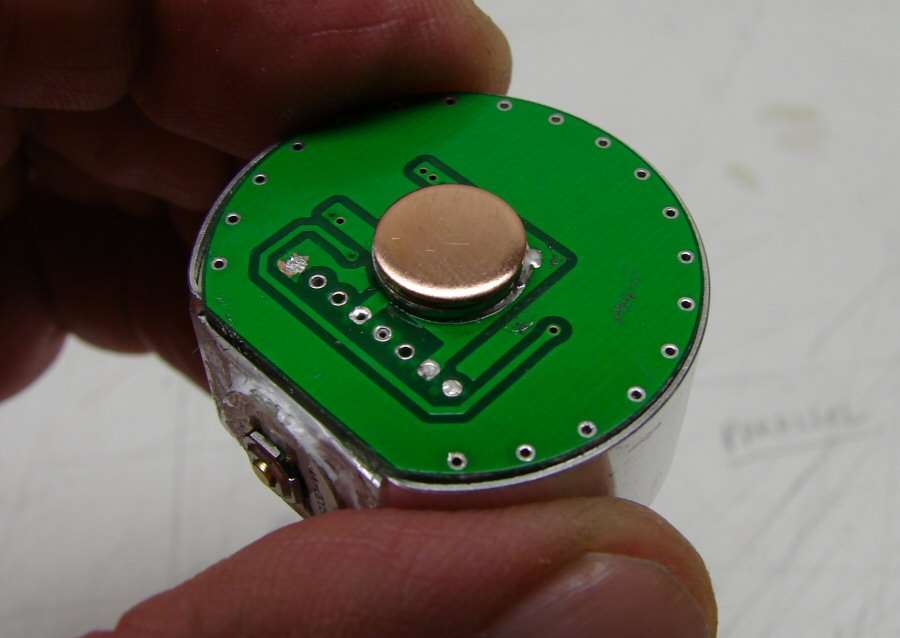
I stripped the original driver, so I can use it as a contact plate. There's plenty of room for the DrJones driver, even with a few extra chips added on.
I will be using an SMD switch out of a rook, but I haven't decided to keep the ugly stock white cover or go to a black one.
I have to go to work early, so I can stop at Home Depot and get some PVC for battery sleeves, for the 18650 and 26650.
------------------------------------------------------------------------------------------------------
The De-doming ended up a fail. I tried two XM-L2 leds and they de-domed really well, except where the wires were. Never touch the wires, never, ever, not at all. Hell, I can't even see them wires with the magnifier... Oh well, I have some XM-L leds laying around, one of them will have to work. Not spending more money for XM-L2, when I have something else in the bin.
------------------------------------------------------------------------------------------------------
10-11-13
I got the pill back together
DrJones driver with 11x380mA chips - 4180mA. All the solder spots are covered with AA.
SMD is in place, not pretty, but functional.
XM-L T6 3C. Better than nothing...
Contact plate soldered on.
The only thing I use Fujik for is for filler. I filled the pill with it and it will hold the contact plate in place, (after it dries in a couple of days, that is).
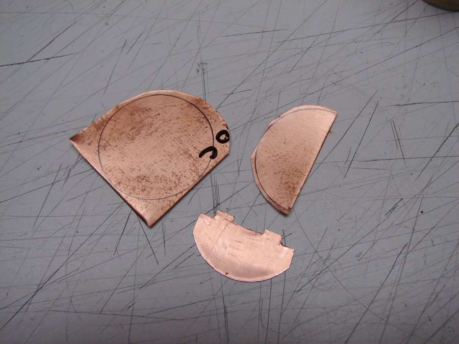
Started working on the parallel battery holder. The contact plates have to be different from series. All four contacts on each end need to touch, so I cut out a copper circle, halved it and made it so the two halves would slide back together. Here only one half is cut.
Here's how they will overlap. Soldering them together in the holder is an issue. Plastic melts way before solder does, so it will be a bear to do it.
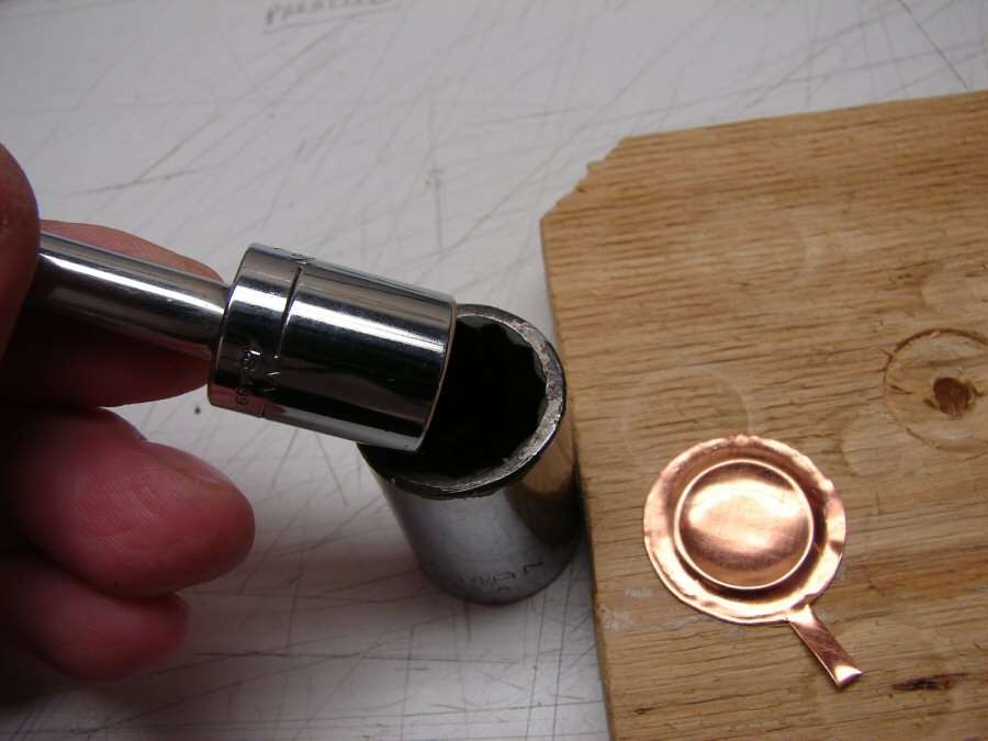
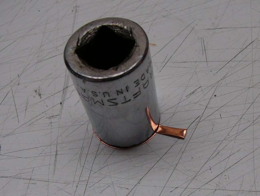
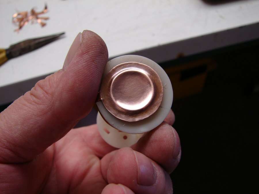
This is the negative end, so I am making the negative contact plate that the tail cap spring will come up against. The tab will wrap around the holder, to be soldered to the inside plates in the previous photo. I use two sockets. The small one will slip inside the big one and that's how I gauge which ones to use.
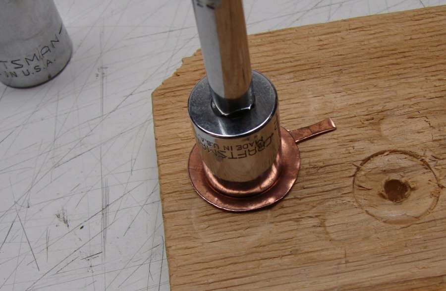
Hitting the small socket on the backside of the copper plate against a piece of soft wood, allows for a raised ring to be made.
Then the large socket is used to flatten out the outer edge, which gets all warped when the small socket makes the ring.
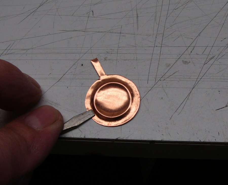
A serewdriver can be used to do the final smoothing on the outer edge.
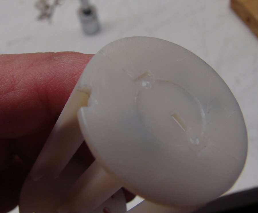
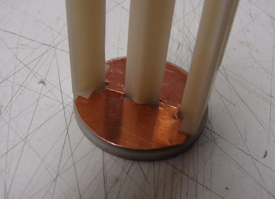
Battery holder notched so the tab will fit in it, as it's wrapped around.
Four gold plated springs were soldered to the plates. Then I soldered the tab from the bottom plate where it needed to be and put it all together. The two halves are soldered together enough to make good contact all the way round.
The bottome plate still needs to be cleaned up and glued to the holder, but you get the idea. I still need to make the positive end and the other holder, but at least you can get an idea of how to make a low resistance battery holder out of a cheap Chinese one.
------------------------------------------------------------------------------------------------------------
10-13-13 It's Finished!
Hey, I actually finished one. Maybe the loosing streak is gone. Only took three drivers, to get it working.
The pill is done and I ended up using a couple copper discs in place of the front spring. Springs are resistance, but the copper should be low resistance.
4xAA in series battery holder. It ain't pretty, but it works.
4x14500 in parallel battery holder. It's even uglier than the other one, but again, it works.
18650 and 26650 sleeves. They are not full tube length, so unfortunately, they will slide. I didn't think of that till they were done... but they work.
Copper braid mod for the TC.
So now the light can run on a 32650, 26650, 18650, 4xAA, 4x14500 and even 3xAA Alkalines in a pinch. That's a very versatile light!
======================================================
Amp Draws: (the DrJones driver has 12 chips on it - 380mA each).
4xAA - 4.5 amps on high (Eneloop first gen) - (Was 1.6 amps in the stock light)
4x14500 - 4.5 amps on High (Efest IMR)
1x18650 - 4.5 amps on high (Panasonic 10A battery) - (Was 2.4 amps in the stock light)
1x26650 - 4 amps on High... Huh? (Trustfire Blue 5000mA couldn't pull the full 4.5 amps, says a lot of bad things about that battery doesn't it?)
======================================================
Lux at 1 meter with an 18650 - 16775 (was 16200 with the old XM-L2 stock)
Lux at 1 meter with 4xAA - 16750 (was 12500 with the stock 4x battery holder in the stock light)
======================================================
So, what did we accomplish?
Better UI thanks to the DrJones driver
We lost out on the led, because I had to go to a regular XM-L T6 instead of an XM-L2 T6
Amp draw on an 18650 went from 2.4A to 4.5A
All battery configurations can now put out 4.5 amps with the right batteries. (Alkalines will not put out 4.5A. They are for when there is no other battery available).
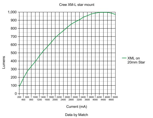
Lux increased "a little", but without a lumens measurement, we don't know how much brighter the light really is. All we know is that Lux at 1 meter increased a little... Well, that's better than a reduction.
Overall, I am really convinced (and have been for a while now), that all these mods don't mean Jack. When you take a led and go from 2.5 - 3 amps, up to 4-5 - 5 amps, you really can't see a noticeable difference, so why are we doing it. All we really did was to make the light get hot faster and stress all the components more, but we didn't really accomplish a noticeable, (to the human eye), difference. I have felt this way for a while. Change from a XP-G to an XM-L and it will be noticeable. Change from a XM-L to an MT-G2 and it will be noticeable, but change from an XM-L, to an XM-L2 or change from 3 amps to 5 amps and it's really just something to do, but it's not really very productive.
Anyhow, the fact that the light can run so many batteries is what this light is really all about and I'm happy with that.
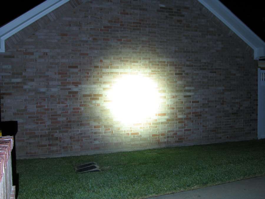
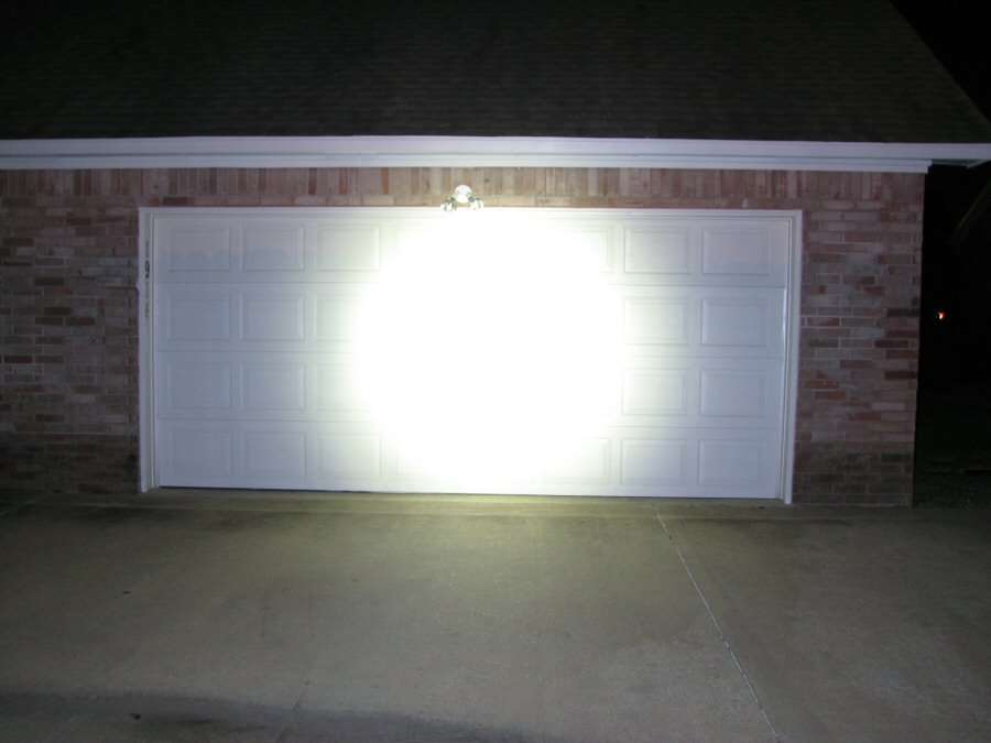
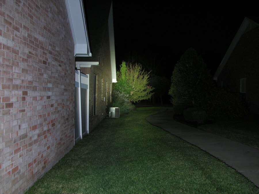
Beam shots tonight and I will compare the old and the new.