TS10 aux LED brightness reduction

I started this thread in response to some inspiration received by jon_slider.

I’m interested in lowering the Aux LED brightness on high in my TS10. On a reddit post zumlin described his approach of reducing the Aux LED brightness on his TS10. I’m thinking of doing this also, but need to find the right resistor.

I also wondered about using a small diode, but I’ve not reached out to any of the modders yet to see there thoughts. I figured I would do a bit of investigating to see if I could characterize the aux LEDs. Or at least it worked out that way.

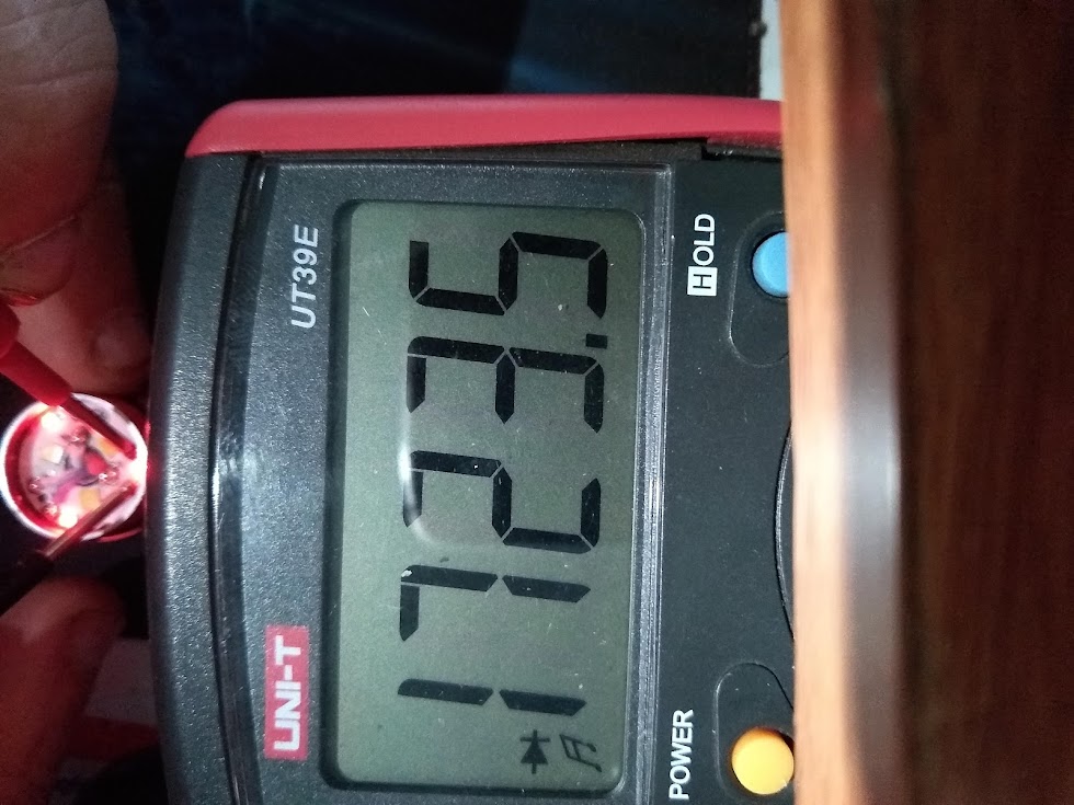
When I use a DVM in diode check mode, I see the aux diodes light up nicely, the DVM is applying 1.72V. It has been reported that with the aux LEDs on high, battery power is about 12mA. It was also reported the driver has a 100 ohms in series with the aux LEDs. What current would flow if there battery, resistor and Aux LEDs are in series? For a 3.7V battery, and say 1.7V across the aux LEDs, then there’s 2V across the resistor. That would be 20mA from the battery, so that’s not right, as there’s only 12mA. There must be only 1.2V across the 100 ohms. Perhaps there’s some sort of regulated output somewhere at 3V or so that drives this.

My numbers are mostly swags. I like the light output of the Aux LEDs with 1.7V across them. So I did some more measuring. With the driver board connected and the Aux mode set to high, I see 1.88V across the aux LEDs. Set to low, I see 1.63V across the aux LEDs.

When I measure the current my DVM puts through the LEDs to get a “nice light” its about 0.4mA. If there is a sort of regulated 3V driving this, then (3V-1.7v)/4.3K is 0.3mA. So this all seems reasonable to me, as zumlin reported that he liked a 4.3k ohm resistor in series.

When I can get my hands on a small enough part to fit in there, I’ll try it out. Hoping in the next week or so, stay tuned for more details . . .

Some pictures of my work today.

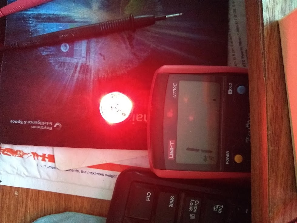
This is the “just right”, using my DVM at the source of power for the aux LEDs

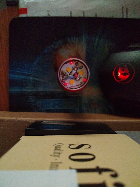
This is Aux high with the driver.

This is Aux low with the driver.

oops, I managed to delete this one . . . :person_facepalming:

Well I finished the mod yesterday. I found some 5100 ohm chip resistors on a laptop battery pack board I had laying around. Took some pics but can’t upload them now. I connected one end of the 5100 ohm chip resistor to the PCB pad and connected the wire to the other end of the chip. Pretty simple.

I figure the aux on high now draws about 0.25mA. Would like to measure it but haven’t figured out how on this light. If I’m right with the provided 900 mAh cell it’s close to three and a half months of cell life for just the aux lights on high.

My preference is blinking though, so the life should be much longer. What I would really like is for the blinking to always report the cell voltage. Seems like it should be easy enough to do.

Congrats on your progress :beer:

Looking forward to actual current draw measurements !! I also want apply the same mod to my TS10

Thanks to Limsup :beer: for some tips on measuring the current draw on this light. Here’s what my modified light measures

Aux off - 4.4 microAmp
Aux low - 173 microAmp
Aux high - 390 microAmp

My meter read .45 milliAmp on the milliamp mode (as opposed to microamp mode measurements above), so take any of my measurements with my uncalibrated meter with a grain of salt.

A bit more current draw than I calculated, guessing maybe the controller chip being active to drive the Aux is part of the difference. Looks like about 3 months with the Aux LEDs on high. Probably closer to 6 months with the blinking.

Pics of the low and high modes after the mod. added resistor around 9:30 on the picture, pretty hard to see, sorry. The difference doesn’t seem great in the pictures, but its very noticable in person.

top pic is High Aux after the mod

low Aux after the mod

Thanks for the thread. I’ve got a TS10 on the way for a Xmas present (for myself…) The aux LED mod is something I’d be wanting to do.

0.45mA = 450uA, so your multimeter is in the ball park. Measuring current flow that low is not easy.

Ill try to get hold of a 5k resistor to do the mod. If possible, can you share some pictures of the terminals where you soldered the resistor? It would be a great help

I didn’t solder onto terminals. I removed the bezel to expose the MPCB (?) that holds the 3 main emitters, and 3 aux LEDs. There are 4 wires that connect to the MPCB. There are 2 pictures in post 5 above. There are red and white wires on the right side of the light, ignore those.

The blue and white wires on the left half of the MPCB power the aux LEDs. First I disconnected the white wire. Then, from post 2 above,

The chip resistor is either a 0603, or 0402. Its very small, and is hard to see in the pictures in post 5. Its on the left half of the MCPB, and some signs of where include discoloration of the white MPCB where my soldering iron touched it. I included a zoomed in picture at the end of this post. The black speck between the white wire and the empty pad on the left of the MPCB is the resistor. I simply but soldered the wire to the right side of the resistor, no terminals or pads there.

The picture below is oriented similar to mine, and shows the MPCB better. Credit zumlin. It has a different mod, but shows the white wire on the left and the pad where it goes. That approach was a potentiometer in the middle of the MPCB. Same thing, different part. I didn’t have to cut any wires for my mod, just remove white wire, solder chip to MPCB pad, solder wire to chip, done. Net result is 5100 ohms in series with the white wire.

Hope that helps. Tried to take my own picture similar to that above, but my phone isn’t up to it.
Zoomed in picture of my mod again for reference.

1 Thank

Yeah, I was just commenting that I got two different readings on different settings of my DVM. 390 micro on the microamp setting, and .45milli (or 450 micro) on the milliamp setting. Somewhere around 10%, not terrible for this low of current.

Christmas is early this year, hope my description and lousy pictures help you!

you might have better luck if you take the photo during daylight

anyway, here is a pic from this post
that shows what you describe:
.

Yeah, I did, take pictures during the day, but I just couldn’t get better than what I took. I couldn’t focus close enough. Perhaps direct sunlight is the trick though . . . .

Thanks for sharing that picture, it shows what is possible, and looks better than the job I did! The modder used a 2K resistor, I used 5.1K, what you have in that range will work fine. I personally wouldn’t go lower than 2k is I suspect it starts getting rather bright, YMMV.

hope you figure out a working photo setup,

this is at my desk by a window, this morning… different flashlight, but you get the picture… lol

Congrats on extending the runtime of your High Aux….
I appreciate your post, it helped me understand the process

hope your mod serves your intended application well :beer:

@jon_slider
Apropos photo setup: Can you please enlighten us what you use as a background for your photos? That makes me wonder for ages.

Jon,
What camera are you using? Your photos do look consistently good.

thanks for asking… it is my grey silicone soldering mat I discovered I like it for photos, purely by accident. Before that I tried white paper, and also a wood table… imo the grey background works better.

iPhone 8 w auto white balance. imo, the secret to my photos looking reasonably useful, is 2 things

1. I take photos during the day, my best images seem to happen between 11am and 1pm. Im not fully clear on why… but I know the cct of sunlight varies a lot, over the course of a day…

2. I often use more than one light in a single photo, in which one of the lights is just a cool white, low CRI decoy, to trick the camera into changing its cct and duv reference, so the other lights dont just look “white”

here is a late afternoon photo, that imo does not adequately show how pink the two sw45k leds on left “should” look. the decoy on right is lh351d 5000k
.
here is a pic taken at the same time, just without the decoy:
imo the image is even less useful for showing the tint
.

I think (not sure), that the above two sw45k pics dont look pink because the ambient CCT is 4500K, too similar to the sw45k

here is a photo taken when daylight was at 5300K… Im much happier with how the pink tint was captured in this image, even without a decoy light:
.

I have zero photography training, and no ability to lock the white balance… I think Im mostly controlling the white balance by selecting a time of day when the CCT is high… (I think bright cloudy days are helpful for that reason also)

If I take photos to compare beam colors, I much prefer to have all the beams in the same image… I never get consistent, nor useful results, if I take pics of only one beam at a time, because the Auto White balance changes itself.

IF I could lock the white balance, it might help a lot… Especially if I wanted to take photos in the dark, or under incandescent… which for me are useless (probably cause I cant lock WB)… they look like this:
.

thank you for your feedback!

Thanks, finally this mystery is solved!

That definitely helps now I know exactly the steps I need to execute. Thanks again for the help and congrats for your mod !

[quote=Lumaine Moore]

:beer:

I finally got my hands on the TS10 yesterday - a brass version. Out of the box the (red) aux LEDs were ridiculously bright, but after discovering how to adjust them (7C in OFF), the lowest setting is barely visible- even in the dark. So I won’t bother modding mine- as I’ll most likely leave them off completely 99% of the time.