So we have a lot of questions about the design changes of the hardware, but we can let it go since it seems to work.
We also understand that is designs need to be adapted this means delays.
So lets start with the GOOD, not to be changed or adapted
Logo, nicely done clear and crisp.
Stainless steel bezel, really good depth and finish. looks great
LED centering good now.
Threads sturdy and square, excellent
Two LEDs at the switch very nice
Shelf where the ledboard sits has no anodizing – very good!!
Narsil powered driver, sweet
Overall looks, feel and working, good.
Critical changes
Tom is going to send you the latst version of Narsil to use for the last samples and mass production lights.
You HAVE to:
1 Use XPL V6 3D LEDs
2 Use FET PSMN2R0-30YLDX (in the last prototypes you used PSMN3R0-30YLDX that can cause problems when cell voltage is getting lower and the PSMN2R0-30YLDX is far superior and more reliable)
3 Use different resistors for the switch LEDs (in the 12-15K range, in the prototypes you used 4.7K making the LEDs too bright and use too much power)
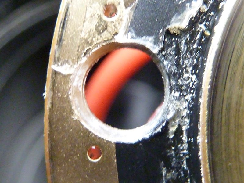
4 Use a 42x1.5mm o-ring for the top battery tube (the o-ring on the prototype was too thick)
5 Use a slightly longer o-ring under the bezel, just a good fitting so no need for stretching to make it fit like in the prototype
6 Use as little glue as possible on the plastic ring covering the screws.
7 Make sure anodisation is good: Tom noticed some spots on the threads where the anodizing is off and chipped.
8 Make sure finish of metal is good, Tom damaged batteries because of burrs inside the tube.
9 the switch cover, see attached picture, need to be long, either leave it whole so people can cut it to the lenght they want or just remove a little bit, if too much is cut the switch does not work nicely. Maybe leaving it long makes sure all switches are the same where cutting could ake some too short thus causing complaints.
Besides critical changes that are absolutely needed could you see if this can be done?
Make the beautiful copper ledboard a little thicker
Make the integrated shelf 7mm thick as it was in prototype 1 (in prototype 2 it was 5mm)
Use a driver retainer ring to protect driver from wear and tear when (un)screwing battery tube.
An explanation on why these changes wre made would be appreciated:
We noticed the thickness of the shelf has been reduce by about 2 mm, from 7 to 5. Was this needed or done for a reason?
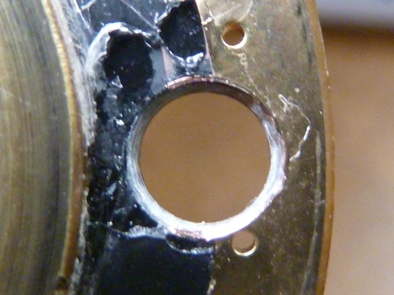
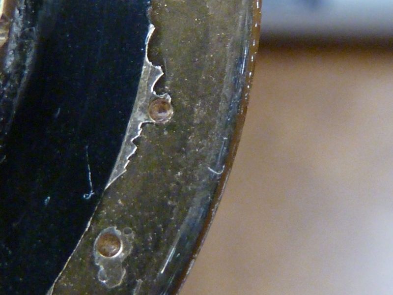
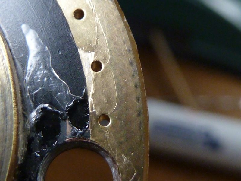
We required a driver retaining ring originally. With these new prototypes, it was eliminated and replaced with screws. The holes in the driver PCB are fairly rough. We are concerned if this will not be improved upon in production, and possibility of screws over tightened and/or stripped in assembly, or possible damage to the PCB. We think cost may have been the motive for this change. We just want to know the reason behind this. We understand cost can be an important justification – that’s fine. We just don’t want to see it cause any possible new quality problems in assembly and manufacturing. Another side effect is the overall driver diameter dimension – it’s bigger now than standard SRK size drivers. I see it has to be in order to make contact with the tube when tightening, because of the screw and plastic ring changes. All these design changes are connected, so we understand it’s too big an effort at this point to change much here. Could you ask the engineers for comment on this? Again, we don’t want to set the project back or add costs unless required.
The LED board (MCPCB) is 1.2 mm thick and matches the depth/width machined out area on the shelf. 1.2mm is a bit thin for a good copper DTP LED board – 1.6 mm is more typical and common. It would be great if the machined out are could be cut to 1.6mm and the LED board thickness increased to 1.6 mm, but again, we don’t won’t to add much cost or complication at this point. Also if the diameter could be widened by 2 mm, also a big advantage. What do the engineers think?