Emisar D3AA is available now

I am planning to order a DT8K and could not find answers to questions regarding the dual channel version’s Turbo behavior. With FET enabled, only ch1 will be driven, that’s clear. But without FET enabled, on a linear 12A dual channel driver, which is true on Turbo?

  • a) ch1 and ch2 are both driven at 12A each, for a total of 24A
  • b) the 12A are distributed over both channels for a total of 12A

This is relevant for my targeted configuration with ch1 being 519a 5700K and ch2 519a 2700K DD.
Because, if option a) is true, FET will only be marginally more bright, as 519a’s do not benefit from more than 6A, thus making FET only be really useful up to 24A for four 519a emitters.
On the other hand, if 24A were distributed over 8 emitters, they would be more efficient (lm/W), and thus be as bright as ch1 on FET, possibly offsetting the lower CCT and dedoming losses. It would also make for an impressively rosy beam, mixing 5700K and 2200K.
If b) is true, enabling FET would evidently make sense.

I’d appreciate if someone could help clarify this.

Also, is this behavior going to change with the new multichannel firmware by @ToyKeeper ?

1 Thank

Yes, and you should probably be using the new multi-channel firmware.

If I understand correctly, there are one or two flavors which can be used on a dual-channel DT8K: emisar-2ch, and emisar-2ch-fet

They have different behaviors. I’d recommend the no-FET version when possible, because the firmware for that is generally nicer, but if you must have a DD FET, it’s an option. Anyway, the channel modes currently are:

emisar-2ch:

  1. Channel 1 only
  2. Channel 2 only
  3. Both, tied together, max “200%” power
  4. Both, manual blend, max “100%” power
  5. Both, auto blend, reversible

emisar-2ch-fet:

  1. Channel 1 only (linear + DD FET)
  2. Channel 2 only (linear)
  3. Both, tied together, max “200%” power + DD FET at top of ramp
  4. Both, manual blend, max “100%” power + “200%” and DD FET at top of ramp
  5. Both, auto blend, reversible (linear only)

You can choose whichever channel modes you want, and disable the rest.

I generally use the emisar-2ch version with no DD FET… and the channel modes depend on what LEDs the light uses. I typically go with modes 1 and 2 only, or 3 and 4 only, depending on whether I want to toggle between different sets of LEDs or blend.

The other channel modes are still available for strobes and such, even if they’re not enabled in ramping mode. So candle and lightning can use the auto blend, for example.

If none of those channel modes are what you want, it’s reasonably straightforward to add more.

If you want the highest power available though, just get a single-channel light. That way, the DD FET powers all 8 LEDs instead of just 4.

2 Thanks

Sorry to bother you, but how do I unhide hidden channel modes?

I just got a triple-channel and can’t tint-ramp channel 1 with the others.

Thank you!!!

In ramp mode, use 9H. It goes through channel modes in order. Release when it gets to the one you want, then it flickers for a few seconds. Click while it’s flickering. Zero clicks hides the channel, while any non-zero amount of clicks un-hides it.

1 Thank

Thank you, your service is as quick as Hanks!

I have made a triple channel RGB D1K using mostly off-the-shelf parts. Did it some time ago but don’t think I remembered to post it.

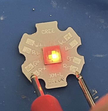
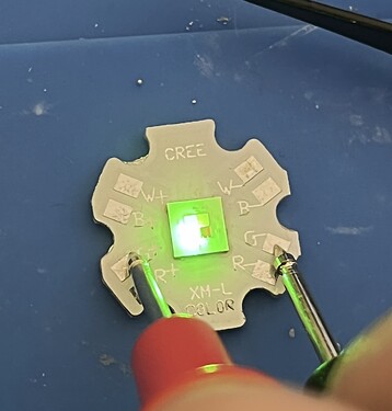
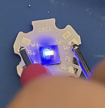
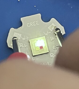
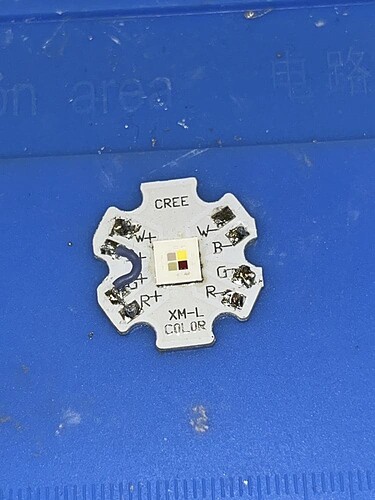
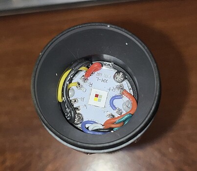
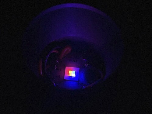
Used an XM-L Color G2 HI (RGBW but white is unused) from Digikey (4000k version) and a Ledil Olga-M optic to smooth out the beam, and connected the positives on the MCPCB with a scrap bit of wire. One of the pads ripped off the original switch so I used a spare where one of the red aux leds was broken.

Build pics below


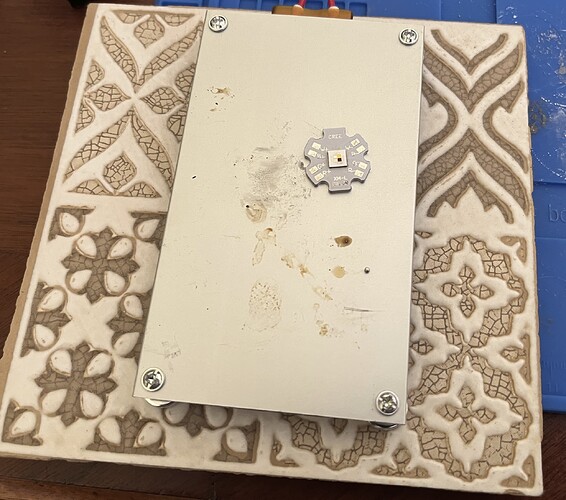
Reflowing the emitter. Used a ceramic tile to protect my desk from the heat of the sketchy hotplate. Worked good and was cheap.


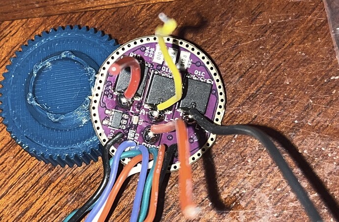
Driver pic, because I don’t think anyone had posted the other side of a 3ch driver. Also note the wire colors and labels (red=A, yellow=B, black=C) This driver was custom ordered to be 2.5A per channel, it looks like all 3 sense resistors can be swapped out without removing the driver from the light, pretty convenient for anyone modding a D4K 3-ch in the future.


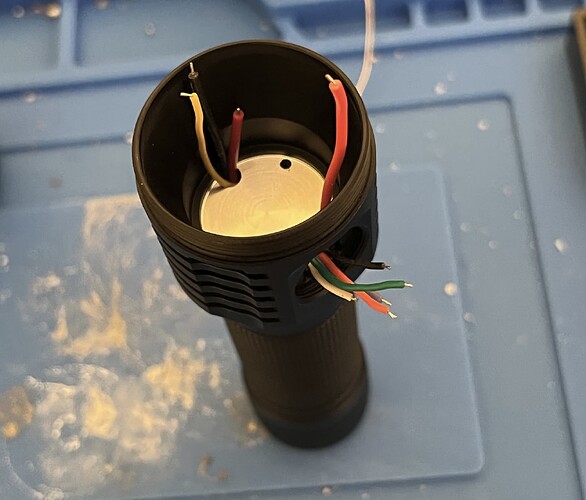
Was pretty tricky to fish all the wires through, but I was able to get it done eventually. My plans to put an RGB Aux board on it are pretty much done for though, unless I got comfortable using much-thinner teflon-coated wires


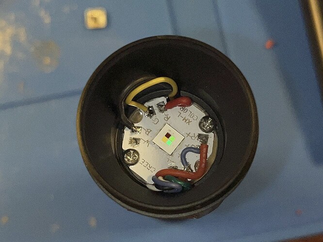
Positives connected in common. Eventually I touched it up to get a better connection between R and G.

Semi-finished light, with all the soldering done for now. Not my neatest soldering but it was pretty tricky either way.

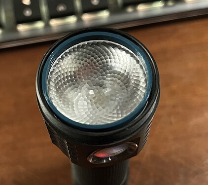
Eventually I had to tuck the wires neater so that the optic could sit all the way down and focus properly. I 3d-printed a ring that acts as a spacer and holds down the optic in the host. It is made of PLA+ but the light doesn’t get very hot so it should be fine, seeing how it’ll only draw 5A at most.

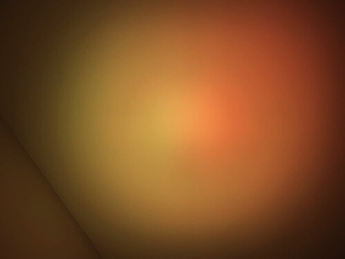
Don’t think I remembered to take final assembly pics or beamshots so I’ll attach them in a later edit. The color blending isn’t as good as I originally hoped, but it still works pretty well. It might become better with some DC-fix on the lens, but I don’t have any right now.

Random notes:

For whatever reason, when using stock firmware, going through the channels wasn’t RGB despite being soldered in the right order, the order when doing 3C being RBG, not sure why they are switched when using the default firmware. Either way, huge thanks to @wolfgirl42 for helping me by putting together some customized FW for this light.

There’s also a issue with the ramp shapes, but I haven’t figured out that one yet. I think it has something to do with 1 ramp being for dual-emitter and the other 2 being for a single, so when I switch from blue/green to red it gets a lot brighter, despite the moonlight being the same.

There’s also a few features I’d like to have, specficially one that synchronizes the color of the main emitter with aux, so that it too can behave like rgb aux (on moonlight). Another nice thing to have would be an auto-rgb mode that just keeps the light in hue-ramping.

EDIT 1: More pics
10 Thanks

Amazing job! :tada: Thanks for taking the time to share it with us! :+1:

3 Thanks

It’s a side effect of using 3 channels on attiny1634, which has only 2 16-bit outputs. The other output is 8-bit, which causes a big loss of resolution.

I have some ideas for a workaround, but I don’t have anything working yet. Long-term, the plan is to move to AVR DD, which has more and better outputs.

1 Thank

Honestly I would be fine with just 8-bit ramping. Maybe for this use specifically it’d be better to just use 8-bit (or mirrored 8-bit) for all channels.

The workaround idea is to use 8-bit ramping… but also finally add delta sigma modulation, which I’ve been meaning to try for years. It’s a method to increase the effective resolution by rapidly changing the PWM level between two adjacent values, to get an average which is somewhere between.

If that works out, I’ll probably use an internal resolution of 15 bits, so the UI can use 0 to 32767, and the top bit is a way to simulate having a carry flag during additions (which the MCU supports, but only in assembly because C doesn’t expose this feature).

3 Thanks

First time I hear of this. At first I thought you were referring to the half-carry flag, but on second thought it would not make sense in the context you described.

Yeah, not the half-carry flag… the regular carry flag. It’d be super handy if C exposed that somehow, to find out if an int rolled over during addition.

Since that’s not available without assembly, I can get more or less the same thing by using a 7-bit int instead of 8-bit. I think it’ll probably work if I do 8 bits of PWM plus 7 bits of DSM, to get a dimming range of 0 to 32640.

The 32640 figure is 255 << 7. It occurred to me that I can’t go all the way up to 32767, because then it would try to roll over 255 sometimes, and it’d go back to zero.

Also not sure how to handle clock speed changes on something like this. It’d probably have pretty noticeable bumps in the ramp each time the clock speed changed. So on a regulated driver, I’d probably just stay at the same speed all the time. Otherwise, I’d need to finally rewrite the ramp calculator to properly handle speed changes, and that’s hard.

Anyway, I’m working on adding DSM to the emisar-d4k-3ch build. I can’t make any promises, but if it works, it should fix the poor resolution (and bad ramp shape) of the main channel… and may also improve the other channels too.

2 Thanks

Do you think the DSM will be able to make moonlights lower as well? They’re still pretty high on the multichannel and boost drivers from Hank.

Also, did you get around to adding saturation ramp to the 3ch firmware? Even in the 2.5D ramping mode instead of full 3D channel ramping.

OK, I think I follow you now. Well, having faced this kind of issue more than once, what I do is (a) use an unsigned int datatype (uint16 in the specific case you mention, IIUIC) and (b) check whether the result is less than either of the operands, eg:

uint16 op1, op2, result; 
[...]
result = op1 + op2; 
if (result < op1 || result < op2) { 
   // roll-over
}

Sorry if I’m stating the obvious, but over the years I found this method works well and is much more legible and portable between datatypes than the alternatives I’ve seen so far. OFC it does extra work, up to 2 comparisons, tho – so it would not serve if you are eg in an ISR and can’t afford the extra cycles – but experience has taught me that in these cases it’s best to code the entire ISR in assembler to begin with.

I rewrote the d4k-3ch code to make it use PWM+DSM on all 3 channels. Here’s the current build, for anyone interested in trying it:

https://toykeeper.net/torches/fsm/anduril2/anduril.2023-10-13.emisar-d4k-3ch.hex

It greatly improves the resolution of low modes on the 8-bit channel, and moderately improves the two 16-bit channels (mostly with reduced flicker and a bit nicer low modes). It also makes extra-smooth ramping even smoother, like when using sunset mode or thermal regulation. When tint ramping, low brightness levels have much higher tint resolution now. The HSV mode also has much better brightness control, since it’s 15-bit now instead of 8-bit.

It does not make ramp level 1/150 any lower, though. That’s set by hardware and I can’t change it. It’s as low as the hardware allows though… meaning the regulator is on (required to allow any light at all to come out), but its control voltage is zero (lowest possible level).

I also haven’t added saturation to the HSV ramp yet. It’s still just hue and value adjustable, with saturation locked at 100%. But the saturation changes should be much more feasible now with the new code.

Another thing which still isn’t done is the adjustable “white” mode, which would basically be the same as the “all” mode but with adjustable gamma curves.

Anyway, it’s a big improvement but there’s still more to do.

1 Thank

Read through your changes today, I am in awe :slight_smile:

I think a separate floor/ceil per channel might be a useful thing to set for cases like this so if someone wanted they could raise the floors on the other channels - the hard part is going to be how to structure its configuration without confusing people… If you have any ideas I’d be happy to discuss, my first thought is to use the 9H menu somehow since that already enumerates all the channel modes. Maybe as “floor offset” somehow?

1 Thank

Neat. Your post is showing as #6666, on Friday the 13th in October.

Also, my first DSM-capable build came out to 13666 bytes. It didn’t work, but the fixed version is close enough that I could probably get the size the same for a special Friday-the-13th release. :ghost: :jack_o_lantern:

The plan is to have a gamma value for each hardware channel, with … I dunno, an adjustment range of 1 to 32, with 16 being neutral? Then the gamma would be applied in the “white” channel mode, to balance the channels better.

I’ll need to find a quick AVR-compatible method of doing gamma calculations, but that will probably not be a huge problem. Also, not sure where in the UI to put a menu for entering the values.

Another change I need to make is adding a sine wave function, and using it in HSV and auto-tint modes and maybe also in manual tint modes. It’d give nicer-looking results than a triangle wave, but it’ll need a lookup table since that kind of calculation suuuucks on AVR.

3 Thanks

Yeah, if I was going to be in that hotel room for a while, I’d go down to the local dollar store and pick up a few pillow case slipcovers.

If the management is iffy, it could be fun to take a cushion down to the front desk and them demonstrate the… “hidden traces” to the staff. :laughing:

1 Thank

Looks like SFT40 3000k 95 CRI are in stock! I asked Hank a few weeks ago when they’d be in and he didn’t know. So at the time I ordered a KR1 SFT40 5000K and it arrived today.

The tint on the 5000k is very nice! I now want to replace all the greenish 6500k with these or 3000k.

2 Thanks

Any CRI/DUV measurements?

1 Thank