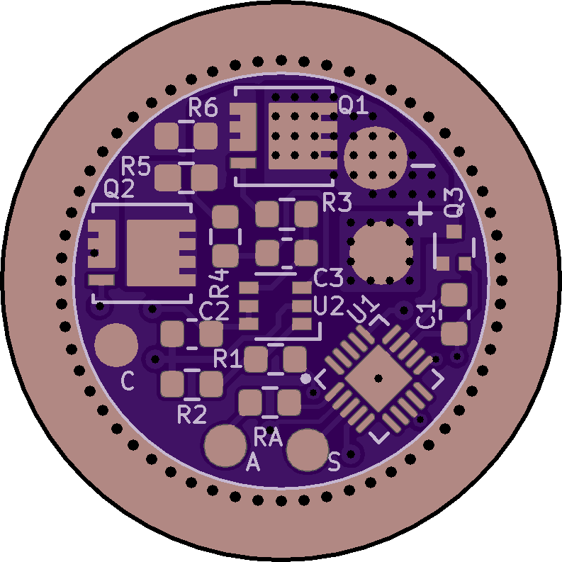
If you need some to build a driver, LCSC has 6000 in stock. Digikey also announces ~90 000 for October.
The new version has arrived! I’ve confirmed compatibility with USB-C to USB-C connections, including hooking it up to my phone and using the freshly updated ZFlasher AVR app. Man, that really does make flashing a breeze. PM me if you’re interested in one.
![]()
AVR DD are available, they have a 10bit DAC and 1.024V/2.5V reference, which means a resolution of 1:2497 vs 1:1159 for the 1 series.
https://www.mouser.fr/c/?marcom=107567063
Up to 32KB in QFN-20 3x3mm
Too bad they have a different pinout ![]()
AVR DU supposedly has USB support which could be interesting for USB flashing/configuration, though it’s not out yet.
Would supporting these need a lot of work ?
Too bad that they switched the pinouts ![]() It’s good to have options though. I haven’t looked fully into coding these, but at least in glancing through the datasheet, I see that the AVR DD still uses UPDI and the register names look to be the same as on 1-Series. So I’m guessing that using these should be an easy change, just new circuit boards to accommodate the pinout.
It’s good to have options though. I haven’t looked fully into coding these, but at least in glancing through the datasheet, I see that the AVR DD still uses UPDI and the register names look to be the same as on 1-Series. So I’m guessing that using these should be an easy change, just new circuit boards to accommodate the pinout.
USB support could be interesting. I’ll have to keep an eye out on these new AVR offerings.
AVR DD support was merged in avr-gcc some months ago. So with the latest avr-gcc it should be possible.
I was making the symbol and noticed that there 2 VDD pins, the second pin is used for PORTC pins if Multi voltage I/O is used (page 188) :
The problem is that the two VDD pins are not next to each other and that can be problematic for layouting. Or VDDIO2 can be left unconnected in dual-supply mode ( ? ) but then say goodbye to PORTC pins.
I thought adapting LIN15 would be faster but the layouting is more difficult with these.
Everything is possible. If… ![]()
I had to use an ADC1 pin for the voltage divider in a driver. Do I need to replace every mentions of ADC0 by ADC1 in fsm-adc.c and is that all what is needed ?
Ugh, I did that once and never again. After looking at the code, I decided it was just easier to solder an airwire to an ADC0 pin (and eventually redesign the board). Voltage sensing and temperature sensing code are mingled together with both pulling from ADC0. To get it working, you’d need both ADC0 running (for temp regulation) and ADC1, which means you’d need to duplicate a bit of code. Maybe it’s easier than I remember, but I would be hesitant.
Oh no, I don’t really have a choice regarding the layout, or I’ll need to use a 4 layer board, not that it’s the end of the world but I would have preferred to keep it at 2 layer.
Edit : I actually managed to reroute to an ADC0 pin.
Nice skills, there! Airwires on those tiny 3x3mm QFN chips are no easy task.
Thanks ![]() Thankfully I could wire it to a side pin, in the middle that’s much harder.
Thankfully I could wire it to a side pin, in the middle that’s much harder.
Is it possible to wire RGB Aux LEDs to different ports ? Like R to a portC pin and B and G to portA pins ? On small and intricate boards it’s often difficult to wire them all to the same port.
The way things are currently coded, they can be any 3 pins on the same port. You might be able to make them independent, but it looks like it would complicate the code quite a bit. Everything is in the rgb_led_set() function within fsm-misc.c
OK, thanks for the answer, I’ll try wiring to the same port.
Boop.
I put together a BLF TINY10 driver for an sf-348 which works well, and now I’m thinking of building a 10mm FET+1 driver next. I’d like to run something Bistro-like if possible so the easiest would be to just use a VDFN attiny13a, but this would mean using a cut down UI, it would have no temperature monitoring and be slightly harder to flash.
How hard would it be to port Bistro to the 1616 MCU? And can it be used in such a simple circuit as the BLF A6 driver?


