Microchip (Atmel) has been releasing some interesting new MCU’s over the past couple of years, their new 0-Series and 1-Series ATtiny’s (eg, the 412, 416, 817, 3217). The 0-Series and 1-Series are nearly identical, but the 1-Series has a few more peripheral options. I feel like they include some new features that, while not vital to our uses, have some benefits. And any guesses on how old our tried & true ATtiny85 is? 14 years, as of the time of this writing (it was launched early 2005). While microcontrollers may not be developing at breakneck speeds, a lot can change in 14 years.
Benefits
- Easier wiring for flashing. These guys use the UPDI interface which is only 3 wires: VCC, GND, and UPDI. Compared to our traditional 6-pin wiring, this makes programming clips easier to wire up and makes programming pads & keys appreciably smaller.
- Internal 32.768KHz ultra-low power oscillator: useful for time keeping (though not as accurate as an external crystal) and can also be used as the main clock source for very low power active states (think ~10uA while active vs the main clock set to 5MHz consuming ~1.6mA )
- New peripherals: RTC interrupts (replacement for what we use WDT for), true TWI/I2C support, multiple 16-bit timer/counters, QTouch touch controller (capacitive touch sensing), an event system that can run while sleeping and perform simple tasks without waking the main processor… etc
- For space-constrained applications, available in QFN (4x4mm) and VQFN (3x3mm) packages
- Internal voltage and temperature sensing (though the ’85 does have this)
- Need a lot of program space? You can have 32KB with the ATtiny3217
Potential downsides
- If you want to stay away from QFN (quad flat no lead) chips and stick with our 8-pin SOIC footprint, the biggest chip so far is the ATtiny412 with 4KB. The ’85, albeit with a larger footprint than SOIC-8, has 8KB.
- There’s not as much information available yet on the 1-Series versus the ’85 which has been used and abused for 14 years
- Coding for the 1-Series is a bit different than the older ATtiny’s - the registers are named and structured differently. So existing firmwares would need to be ported (but not terribly difficult - I’ve ported RampingIOS)
Development Tools
- ATtiny416 Xplained Nano (info) (buy): nice, tiny dev board for testing out code and great for programming off-board chips
- ATtiny817 Xplained Mini (info) (buy): bigger dev board with more options, good for testing out code, and can be used for programming off-board chips (though it’s a bit large if this is all you plan on doing with it)
- To use one of the Xplained dev boards to program an external chip, you simply need to remove 4x 0 Ohm resistors/jumpers to disconnect the onboard chip. Then you can run VCC (from the VREG pin), GND, and UPDI leads to your chip/board. I soldered on header pins so that I could easily swap back and forth between on-board and off-board.
- AVR JTAG ICE (info) (buy): without going the “official” route with the Xplained boards, El Tangas has devised a way to use this as a flashing device (think AVRISP replacement)… though it’s a bit hack-y. In order to use it, you need to flash custom firmware onto it. And then to use it with AVRDUDE, you need to modify the avrdude config file to recognize the adapter.
- My new favorite flashing method (perhaps second to the Xplained Nano) is using a dirt cheap USB to Serial TTL adapter. These can be bought anywhere and can be had for around $1. Common ones use the CH340 / CH341 or CP2102 USB-to-Serial chips. SpenceKonde has a great write-up on these here. You can use these adapters along with pymcuprog, a Python-based open-source utility, created by Microchip itself. Note, you can also use pymcuprog with the Xplained Nano/Mini boards, those actually make things even easier. Another note, my CP2102 adapter had an LED attached to the RX pin; I had to remove this LED in order for the board to work properly.
- This is my favorite USB to Serial adapter. Since there isn’t an RX LED, it doesn’t require any modifications. And it comes with jumper wires!
Windows: Development
Atmel Studio 7 makes dev’ing for this chips easy. Everything is built-in. Just choose the right MCU and go!
Windows: Flashing
- Once again, flashing from Windows can easily be done using Atmel Studio and an Xplained Nano / Mini. Note that if you’re going to flash a different chip than what your Xplained board came with (saying using an 416-XNano to flash an ATtiny412) you need to enable the mEDBG (“mini embedded debugger”?) to be used with other target. AS7: Tools (Main Menu) -> Options … -> Tools -> Hide Unsupported Device -> False
- You can also flash firmware from the command line using “pymcuprog” and either the Xplained boards or the Serial adapter.
- I have not tried it, but you can probably use the AVR JTAG ICE adapter mentioned above and the modified avrdude config
Linux: Development
This is definitely possible. I’ve built hex files in Linux using AVR GCC. The trick to this is downloading and extracting the Atmel ATtiny Device Family Pack and including those files when you compile your code. See my build script here (it’s an offshoot of TK’s build scripts). Note that you’ll need to update the DFP variable with the directory of your unzipped Device Pack
Linux: Flashing
- Recommended: The USB to Serial adapters can be used with pymcuprog
- The AVR JTAG ICE dev tool mentioned above can be used with the modified avrdude
- The Xplained Nano/Mini boards can be used with pymcuprog
Example pymcuprog commands: note that the device path may vary. For Windows, use your com port as noted in the Device Manager’s Ports section (eg, “com3”). On Linux, check the output of the “dmesg | grep tty” command (eg, “/dev/ttyUSB0”). For MacOS, try the command “ls /dev/{tty,cu}.*” To install pymcuprog, first have python and pip installed, then execute this command: pip install pymcuprog
-- erase the chip (recommended to always do this before flashing firmware)
pymcuprog erase -d attiny1616 -t uart -u /dev/ttyUSB0
-- write a hex file and then verify
pymcuprog write -d attiny1616 -t uart -u /dev/ttyUSB0 -f anduril.hex --verify
-- write fuses, this enables BOD in Active Mode
pymcuprog write -d attiny1616 -t uart -u /dev/ttyUSB0 -m fuses -o 0x01 -l 0x04
-- read back the fuse value
pymcuprog read -d attiny1616 -t uart -u /dev/ttyUSB0 -m fuses -o 0x01
Code Samples
- RampingIOS - a port of TomE and TK’s firmware with compile-time options for Single vs Dual Channel and ATiny85 vs 412 / 416 / 817. I have this running on a ATtiny412 in my D25 headlamp right now and it’s working great.
- Smart Tailcap
- Bare LED On-Off testing
- Bare PWM testing
Chip Information and other Resources
- Wikipedia article comparing ATtinys
- Microchip’s 8-bit AVR Quick Reference PDF
- Microchip’s 8-bit AVR Product Listing
- Microchip - Getting Started with the tinyAVR 1-Series
- Microchip - Getting Started with the RTC
- Microchip - Measure VCC/Battery Voltage Without Using I/O Pin
- More reading: tinyAVR 1-Series at JayCarlson
Random Thoughts
- The 412 has a similar footprint to some PIC chips, it makes replacing those easy. I used it as a straight replacement in my D25 headlamp without any funky wiring or trace cutting
- The default clock on these guys is usually 3.33MHz (20MHz / 6). Changing it is easy, but remember to respect the CCP (configuration change protection).
- Note: make sure you’re on at least version 3.10.2 of pymcuprog. Earlier versions have a bug with fuses embedded in hex files. If you need to update, the command is “python -m pip install -U pymcuprog”
- Unlike earlier attiny chips, these new ones actually can have fuses embedded in the hex files. This is pretty handy.
Oshpark Boards
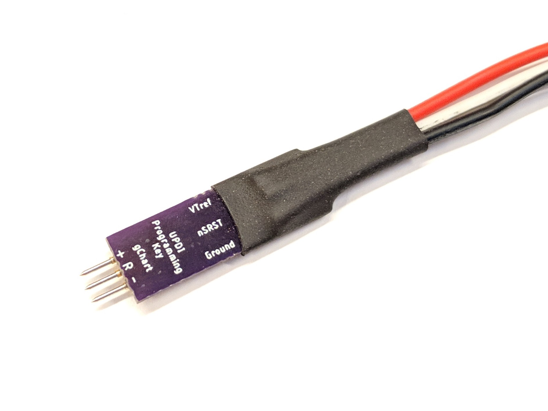
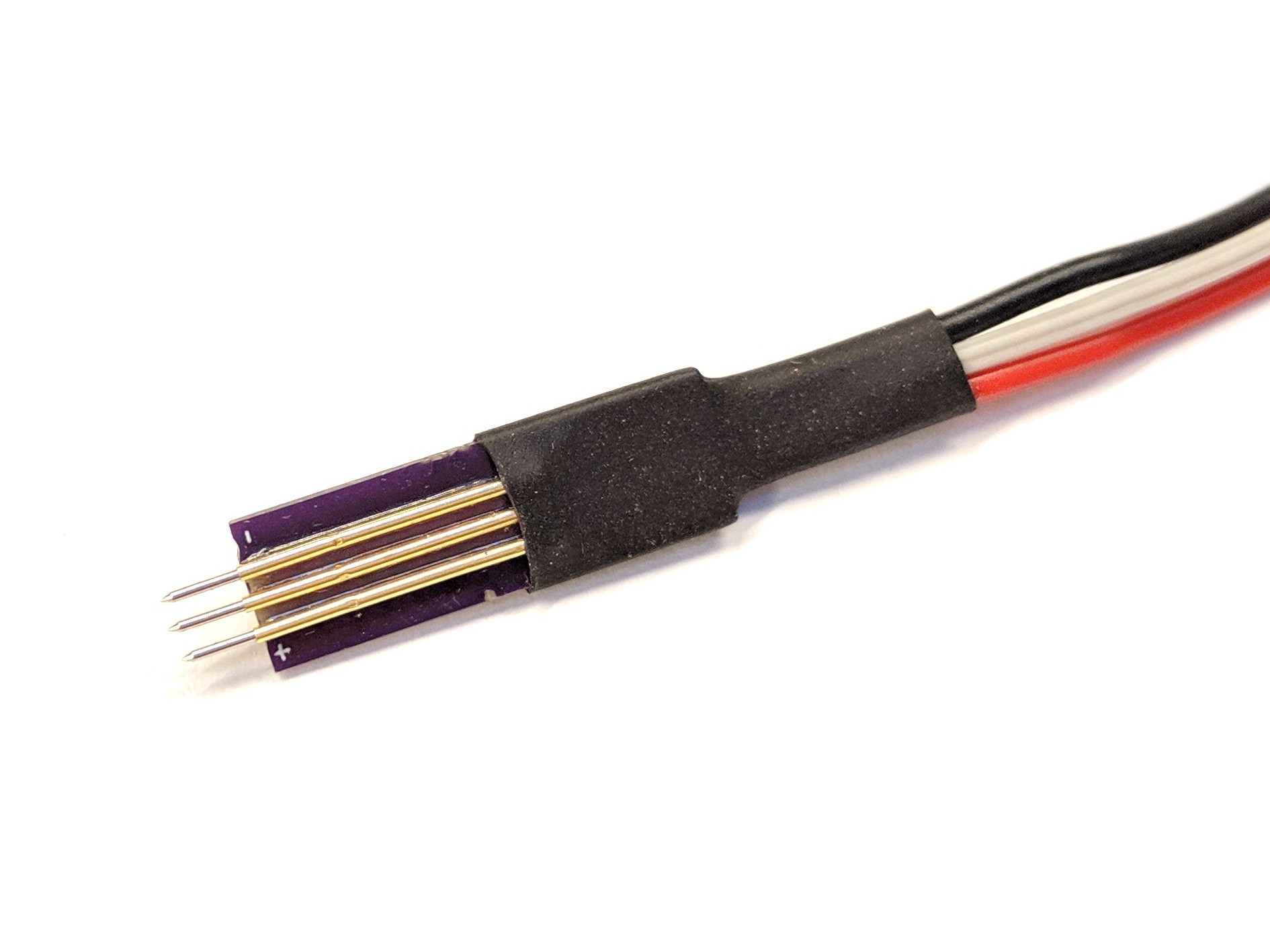
- UPDI Programming Key - can be used with the AVR JTAG ICE or the Xplained boards
- UPDI Programming Key with header - for use with header pins, drops the on-board resistor
- UPDI All-In-One Programmer - programming key with the USB to Serial converter onboard (untested)
- Smart Tailcap - tested, working well; uses the 416
- 3A Single Sided Driver - uses a 416 or 816 and 3x CN5710’s (received, not fully tested!)
- 5A Emisar D1S Driver - uses a 412 and 5x CN5710’s (received, not fully tested!)
- Standard FET+1 t1616 driver (uses the gchart-fet1 build target in my repo)

