Updated version in post #17
A couple of climbing buddies of mine that have seen and bought my hand held lights with my own drivers asked me if I do headlights also, and explained what they miss in current headlights. At first I said no, but after my old climbing headlight gave up I started thinking about it. The main idea is to have a light with a full flooder and a spotlight (not pencil beam, but useable for climbing), with an easy method of switching between the LEDs and mode levels. I decided to take the challenge and have been working with this project for quite sometime now. The ultimate goal is to build one entirely with my own design, both driver and host. I’m nowhere near starting with the host design yet, but I have finally reached the prototype stage for driver and firmware testing.
The first step was to choose a suitable host for prototype testing. I was initially looking at dual LED lights such as the SecurityIng, but for climbing purposes they are not practical as we want the buttons on top of the light, not on the rear. So I settled for this one: Review: Dual LED Headlight from Wallbuys. It’s a nice little light and could have recommended it, but in stock condition it suffers from some quality issues. I read reviews that the generic flood LED has died on a few, and it did on mine after using it during a mine exploration.
When taking the light apart I was glad to see that the driver would be easy to replace, so I designed one in OSH Park with the same shape and holes. Here is my driver (bottom) with the original driver (top):

I didn’t put any components or signal traces on that top left part as my end design will be smaller so I wanted to be able to cut if off easily. I kept it on the design as it has a screw hole and perhaps could be use for E-switch support.
Details of the driver:
- 4 layer board with dedicated power, signal and ground planes.
- MCU is ATtiny84V, 14 pin with 12 in/outputs, 8K of programming space.
- 7 x 380mA 7135 chips per LED. Each group of 7 controlled by 3 outputs from the MCU, enabling any amount of chips from 1 to 7 to run as constant current modes.
- The single 7135 outputs are on the MCU’s PWM capable pins, allowing lower than 380mA modes.
- Back side of driver board is ready for 8 additional 7135s per LED if increased output is desired in the future, each group on their own output pin from MCU.
- Off time cap.
- Zener ready for future MT-G2 or XHP option.
I had the driver board for quite some time before starting, and then programming the firmware to an acceptable prototype level has taken it’s time. My test setup:

As the firmware is now in a usable state I could finally stick the driver into the host. I replaced the original switch with an Omten switch, drilled another hole and put in an E-switch I had lying around. I cut off that top corner as it turned out to be in the way. Component side is towards the back, leaving a relatively flat area for mounting the LEDs. It’s not a pretty build so far, but good enough for prototype testing.

I soldered together two stacks of copper washers and soldered on the XP-L LEDs. I chopped of the end of the reflectors so the LEDs would fit all the way in while soldered to the washers, isolated the unpopulated side with kepton tape and removed some unneeded internal plastic.

It was a bit of a hassle putting together all the pieces, needing to stop to cut and file the plastic several times to get it all fitting. It finally went together:

I need easy access to the MCU as the firmware is no where near completion, so I cut out a hole in the rear. Putting the MCU on the inner side might have been practical for using the MCU’s internal temperature sensor as this temporary host is plastic, but no way I’m a going to screw it apart between flashing. For the final host design I might move it to the other side, but on the other hand that will be an aluminum host designed as a solid heat-sink and I should be able to get readings from the back. I could also use an external sensor.

I still have plenty of work on the firmware to do, but this is what I’ve done so far:
Interface one:
1 long press on mechanical switch toggles between LEDs. 2 long presses after each other enabled both LEDS.
Short press steps cycles through 3 modes, mode direction up only.
Boost mode (turbo) enabled with E-switch only. Holding for less than 1,5 seconds gives short burst (good for signaling to climbing buddy). Holding for longer sets boost mode on until timeout (or additional press) so E-switch button can be released (short blink notifies). Reverts back to mode that was active prior to engaging boost.
Each LED configuration (spot, flood or both) has selectable LEDs for the boost mode. For example: when only flood LED is on, boost is configurable to activate any or both LEDs, and then revert back to flood only when boost disengages. Currently hard coded LED selection, will be user programmable later.
Interface two:
Short or long press toggles between LEDs, double press activates both.
Short E-switch goes to next mode, long E-switch press goes to previous mode. Boost mode is in the mode array, selectable just like the other modes.
Boost times out back to the mode that was active before engaging (lowest or highest mode).
Other stuff:
When both LEDs are on they use separate mode level values (not the same as when a single LED is on alone). This makes it possible to obtain desirable balance between spot and flood in dual LED mode. The mode values are currently hard coded, will be user programmable later.
Boost time out half the time if both LEDs active.
Individual mode memory for each LED configuration (spot, flood, or both).
Voltage monitoring with step down. Boost mode is prevented when voltage level is low or critical.
Hidden functions activated while holding E-switch on startup and counting blinks:
Moon mode, voltage readout, safety lock, interface selection, critical voltage turn off or stay on, reset to default/factory settings.
I added the selection of what the light does when critical voltage is met because it’s a light designed for climbing and caving. In a critical situation you might not care less about a cell and would not want the light to turn off when you need it the most.
This is all pretty advanced, not for all users, so the idea is that it should work pretty well out of the box, and only those who are interested in configuring it should need to read in-depth instructions. Besides my own testing my girlfriend and one of the climbers who gave me the idea will receive prototypes for evaluation and feedback about all this, so this all might change later.
Still to implement.
All modes user programmable.
User selectable mode memory. Remember mode separately for all LED configurations, remember only current mode when toggling LED configuration, or no mode memory at all.
A few more interface options to choose from.
Possibility to run of 3 x AA cells with selectable firmware adapted for AA use (replaceable battery case required).
Still a lot to go, and the light is pretty ugly, but it is usable as long as it’s not raining:

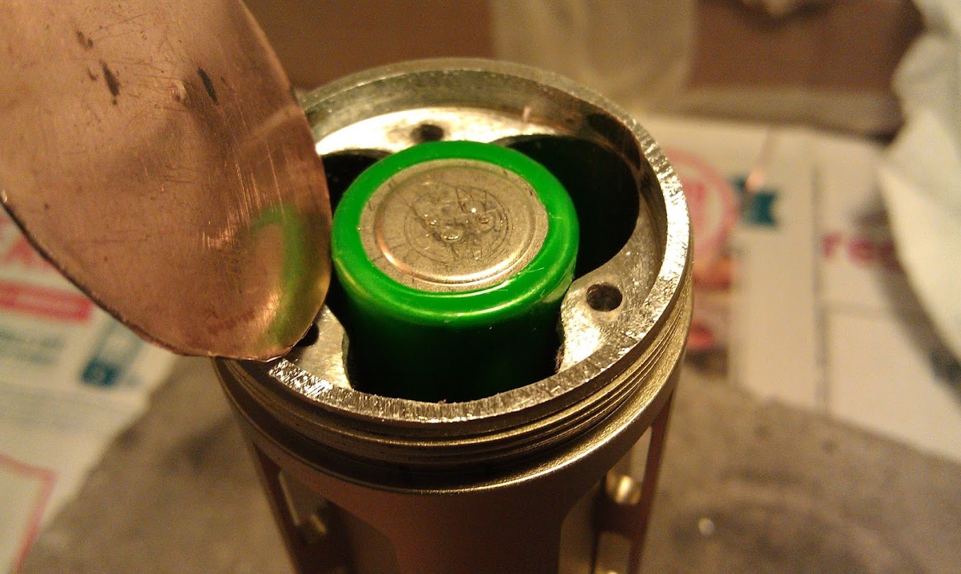
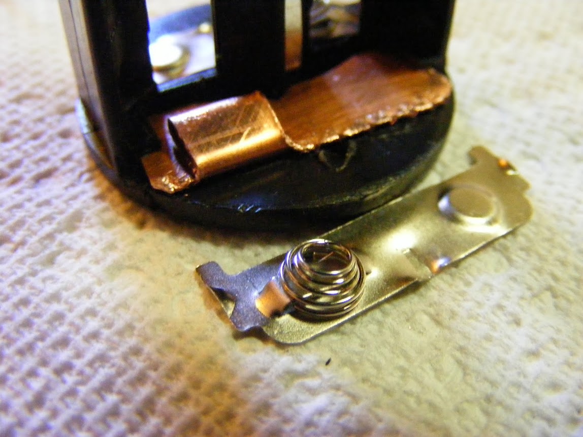
By the way, anyone know where I can get coiled/springy 22awg wire? The stock coiled wire is unusable so now I just have normal wire which is hanging out of the side. Pretty annoying.
Also looking for a better 18650 battery case, both single and double cell cases are of interest.