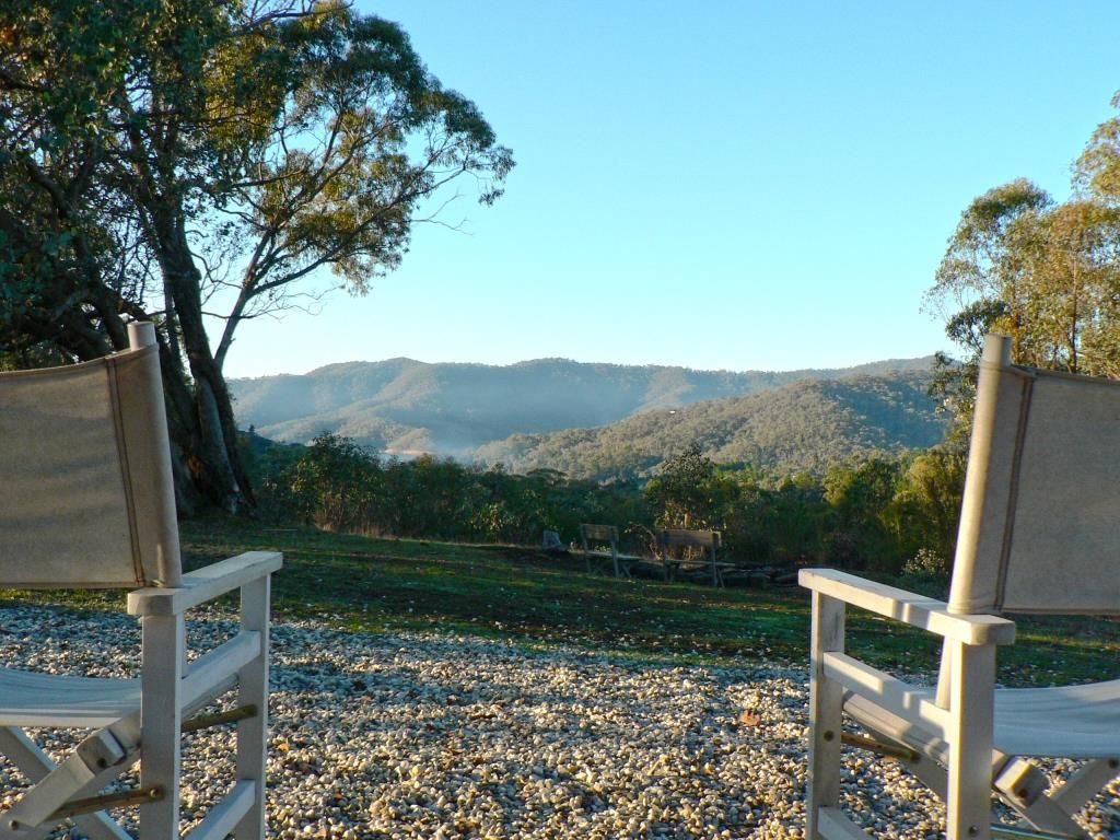
I'm stealing this idea from a certain gentleman here. This is my place to go that I'm lucky enough to be able to visit and forget about the real world. No mains power, internet or mobile phone reception. It really does not get any better. So sit back and chill with a favorite drink and I hope you enjoy the build.
Unfortunately there is nothing new in my build but I will try and incorporate a forward switch which I haven't done yet. As most off you are aware I have a plastic friend holding me back at the moment so will do what I can when I can.
I'm just glad I'm not in hand built as those guys have some crazy ideas that they are actually building. Orsm effort guys.
And finally with the final waffle thanks to OL for having the audacity to put this build off on. What I've seen so far is really inspiring. Cheers all.
The parts that may or may not change. 26650 battery, IOS 4 amp driver with 55 thousand modes, XM-L2 cutter led, copper star, FT switch rubber, C8 lens full of grit from memory from FF, FT switch and a lens I just realized was missing.

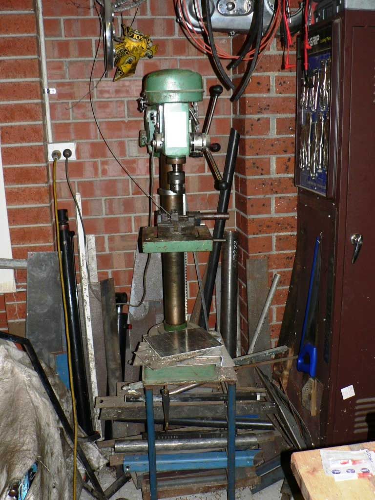
Theres still not a lot happening here so I thought I'd show you some off the tools that will be used in this build. Firstly is the drill press. This is a cheap brand that I bought second hand about 25 years ago. I use the stand to store short lengths off steel.
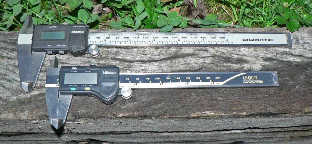
My measuring tools. I do have micrometers but these digital calipers are used 99.9% off the time and are more accurate than I am.
My Lathe. Its 40 inches between centres and has a 1 1/2'' spindle. Its B section v belt driven with back gears for the slower speeds. I bought this brand new as a younger guy in 1982 when I was in my last year as an apprentice fitter and turner.
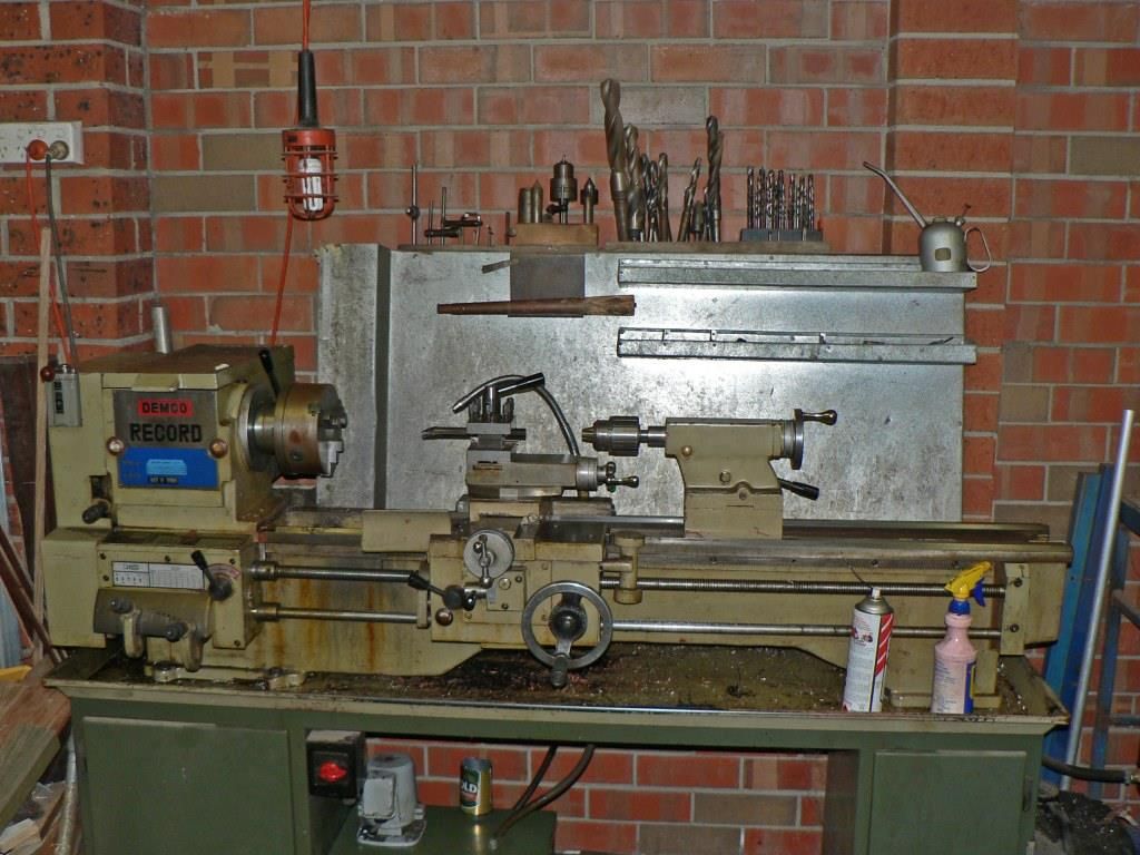
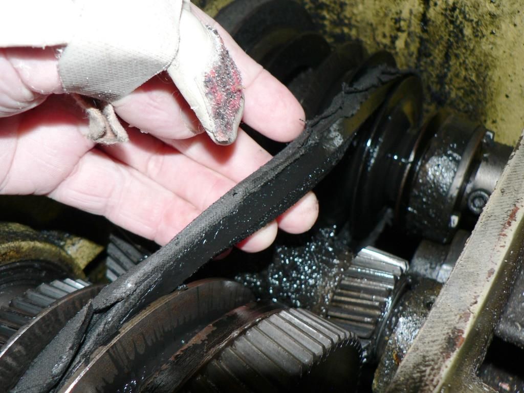
The V belts have been replaced once and well over due again. To replace this belt the whole spindle has to be removed which is not a 5 minute job which is why I have put off doing it.
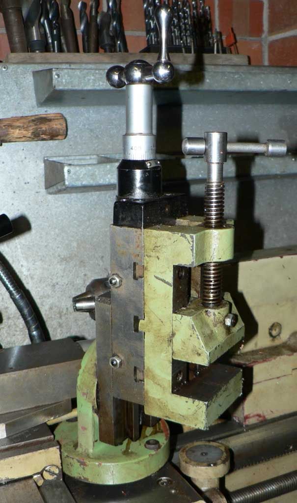
One handy but rarely used option I bought with it was a milling vice attachment. It goes on in place off the tool holder and is only held on with 2 x 8mm capscrews. To say the least its not very rigid hence the reason it does not get used much. The end mills I use are usually old drills ground with a flat end and held in the three jaw chuck.
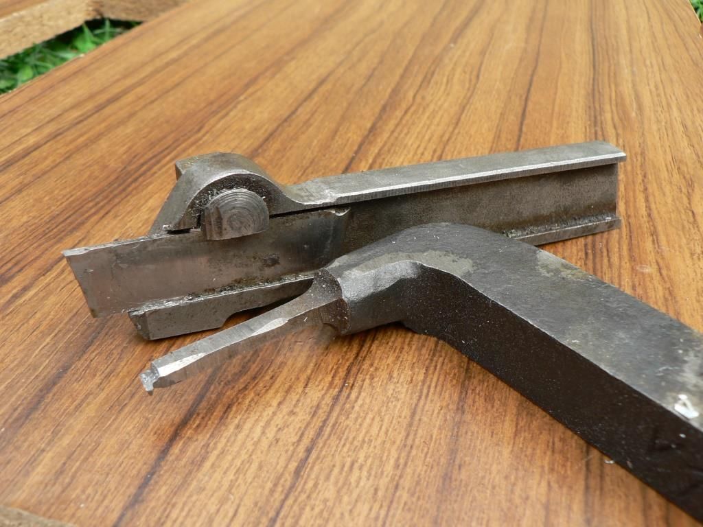
Heres a few off the tools which will be used. A parting off tool which again does't get used much as my lathe is not sturdy enough and an internal tool I use for cutting grooves for o'rings etc. It also gets used as a small boring bar when necessary.
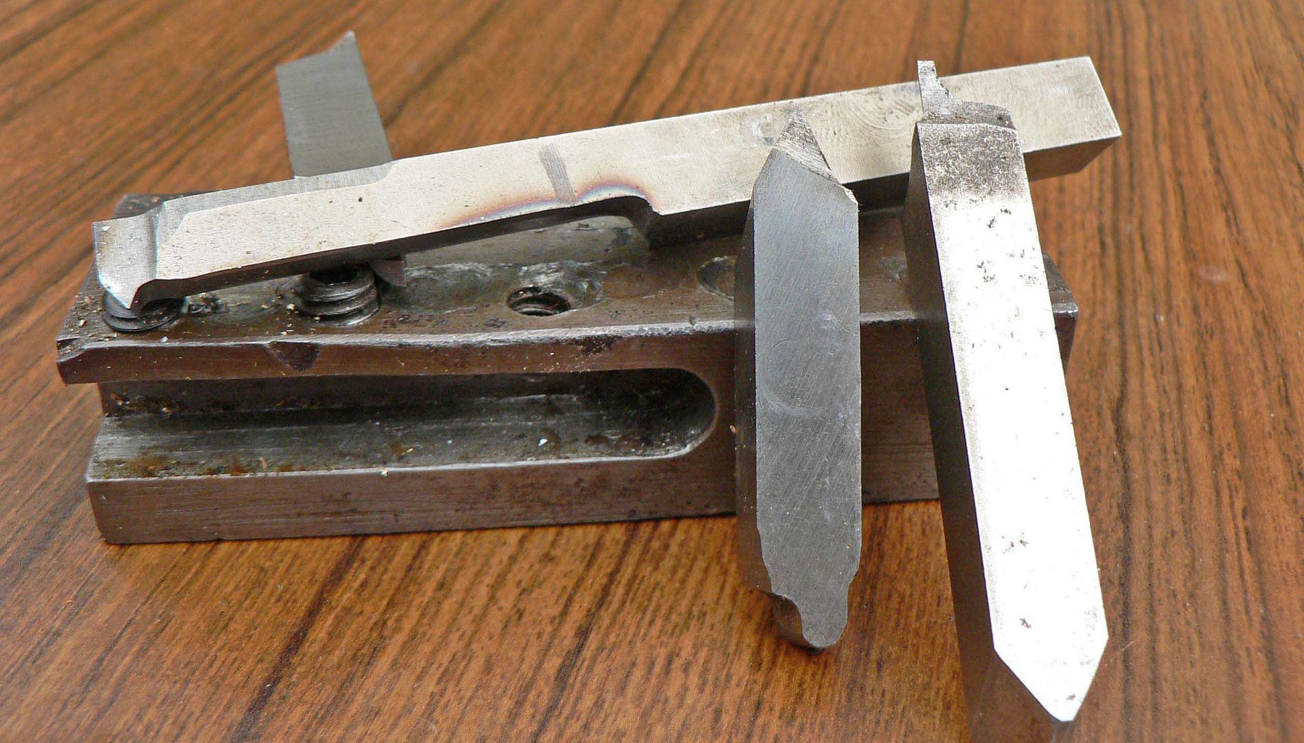
And finally. Most tools I use are ground from 3/8'' tool steel. My tool holder I made when l first bought my lathe with the milling vice and a flat ground 3/8'' drill bit. The long tool on top is used for internal 60 threads. The middle tool is for external metric threads and the right tool is used for external o'ring grooves and parting off. There are a dozen others ground up in lots off weird and wonderful ways for lots off uses.
Its another 10 days before I have any chance off my plastic friend departing my left hand. There's still 6 weeks left in this comp isn't there?
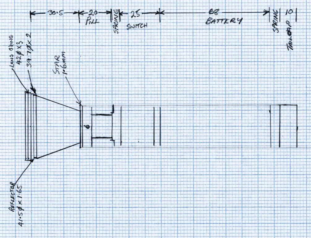
The design is complete, nearly. This will give me a starting point and I will build from here. l have a very rough idea what it will look like finished.
Sorry I lied. I have no idea what it will look like finished. This may just make a good paper plane.
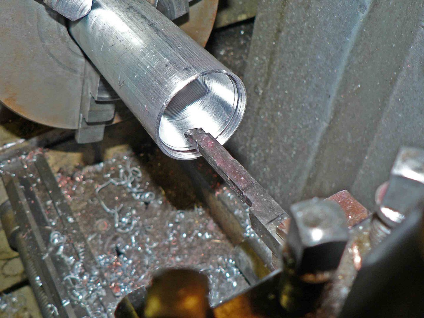
The machining has started. The aluminium bar started of with measurements of 45mm OD and 25.5mm ID.The first picture shows the internal thread cutting after the internal machining had been completed.
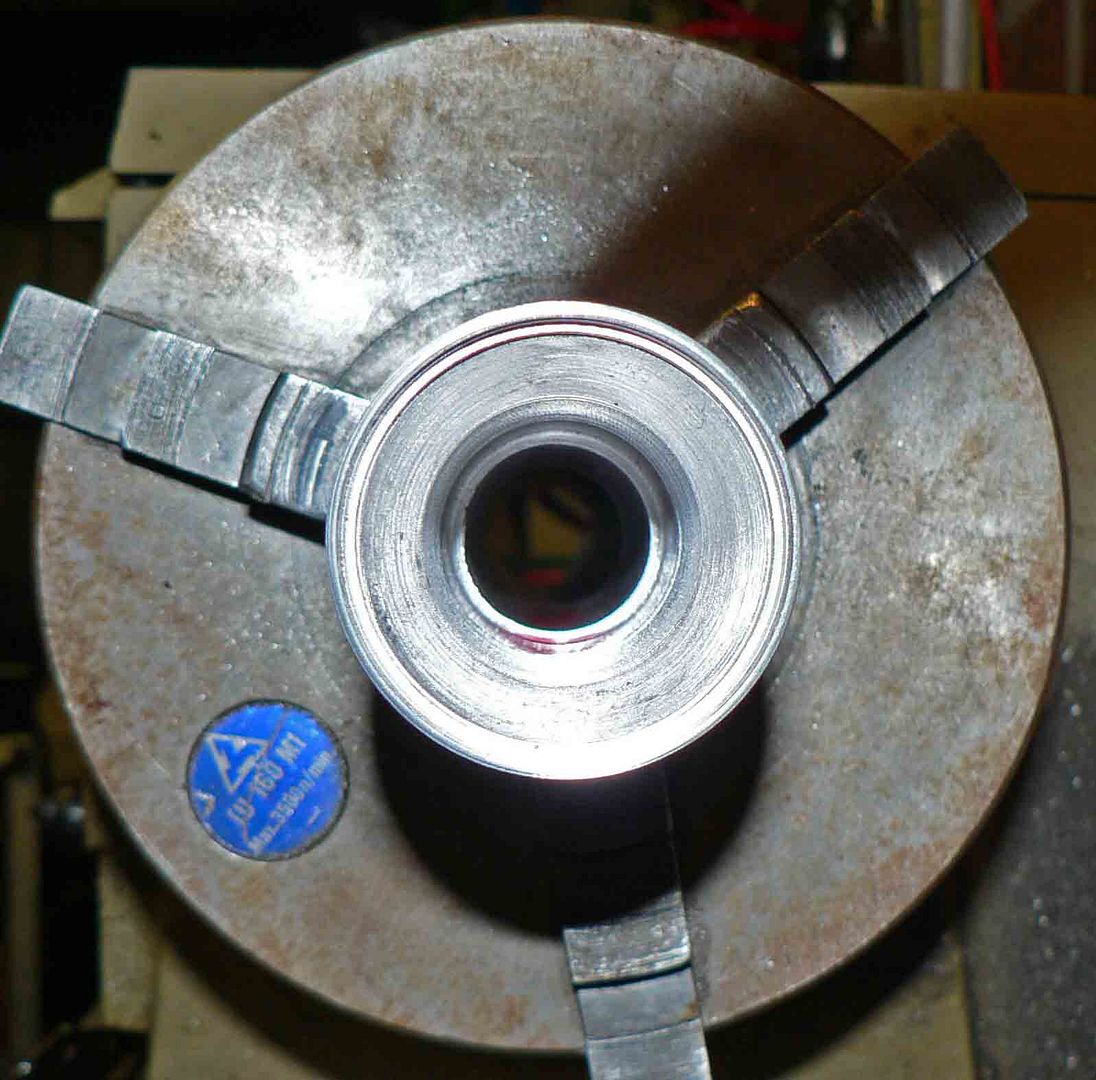
This picture did not turn out very. This is a shot off the inside with the machining finished. The ledge at the rear is 80mm from the front. The switch housing will butt up against this when its inserted from this end. There is a circlip groove 25mm back from this ledge which will hold the switch housing in.
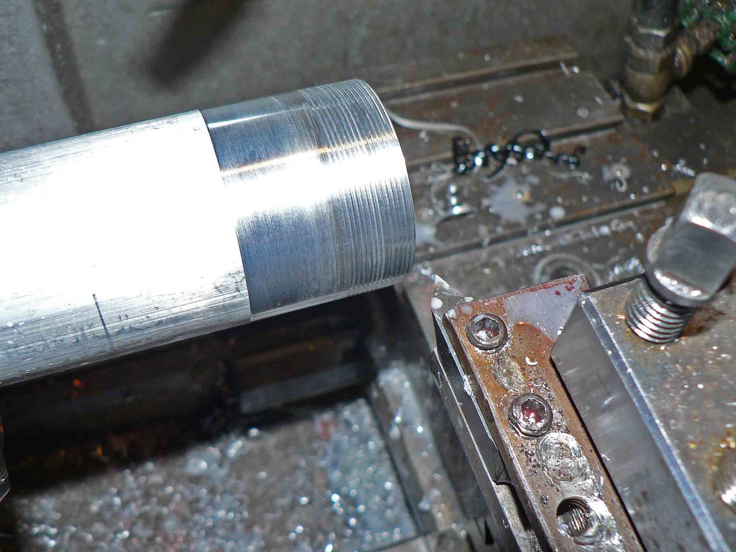
The next step was to machine the thread for the bezel.
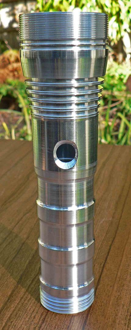
The form off the light is starting to take shape here. The outside was not designed at all as most off you know why. The light will have a one piece tube for the reflector housing and battery tube. The only other parts externally will be the tailcap and bezel.
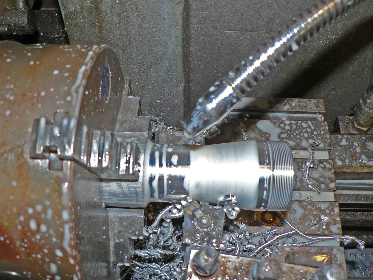
The all important cooling fins are next. These have been designed in a wind tunnel with photons shot at it at mack3 with an MTG-2 led running at 25000 amps shone at it to design the most efficient cooling fins possible. These fins may look just like any other light but in reality will cool better than the light being run in a freezer.

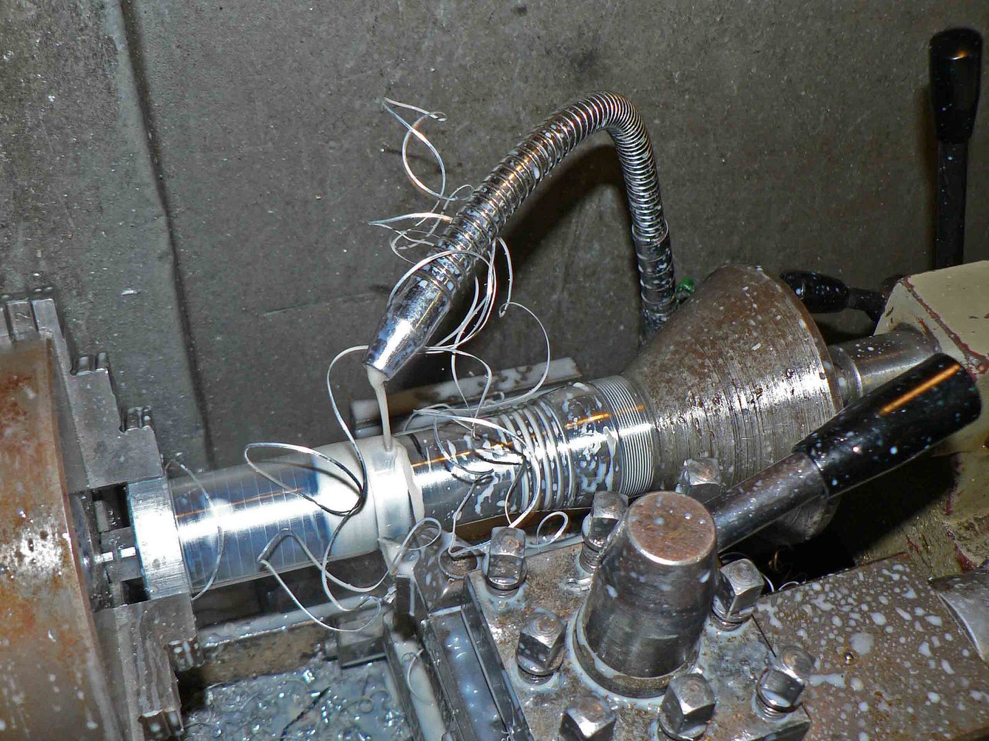
Finally for today, the material is moved out as far as I dared in the chuck (the material I started with was this length without me cutting it) with the reflector end centered with a home made pipe center. This step is the battery tube being machined down to size.
Time for another update. This nearly ended in tears this morning when I was trying to fine tune the plastic switch insert, switch and pins outside in the fog this morning (still more light outside) when I went back into the shed for a blade and came back out to find the switch gone. Noooooooooooooo. Looking around one off the dogs was chewing on something. Yep, it was the plastic switch block. Luckily no damage was caused but one of the pins I had just soldered the wire into and had it sitting in the block was missing. Going into instant panic, as it had taken quite a while to make and I had no material left, I started looking. Again luckily l managed to find it, surprisingly without the wifes help (she was at work anyway) and no damage had occurred. To be honest I dont think I will build anothere switch like this again. Not with a one piece housing anyway as its just to fiddly.
This is the milling vice at work making the switch block and using a drill bit as an end mill.

What it looked like after what felt like about 6 hours.
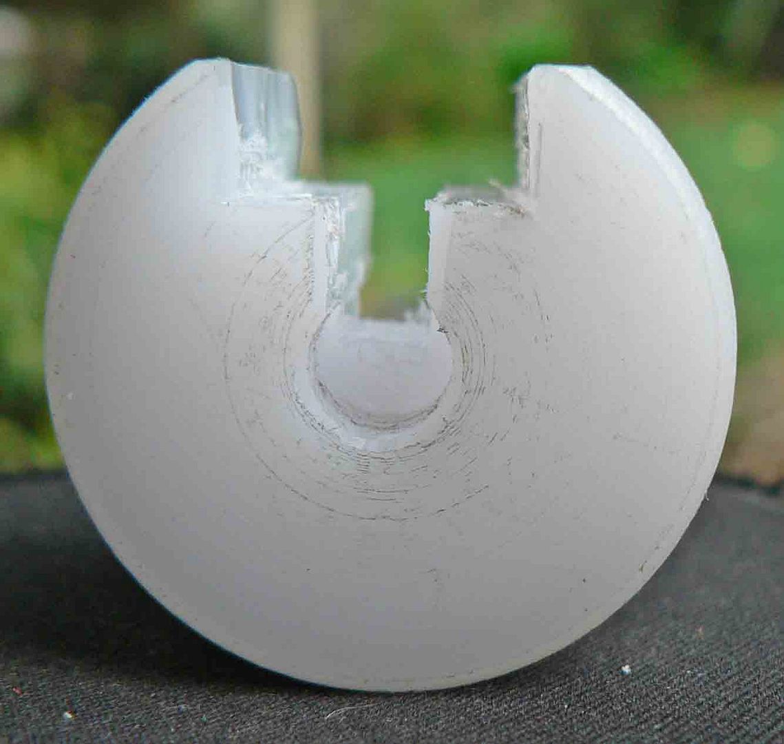
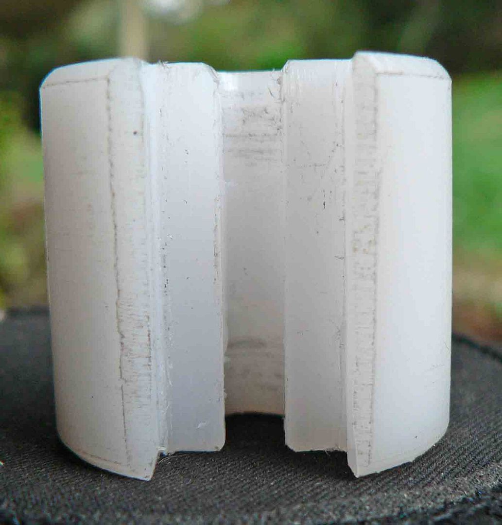
Dummy assembled.
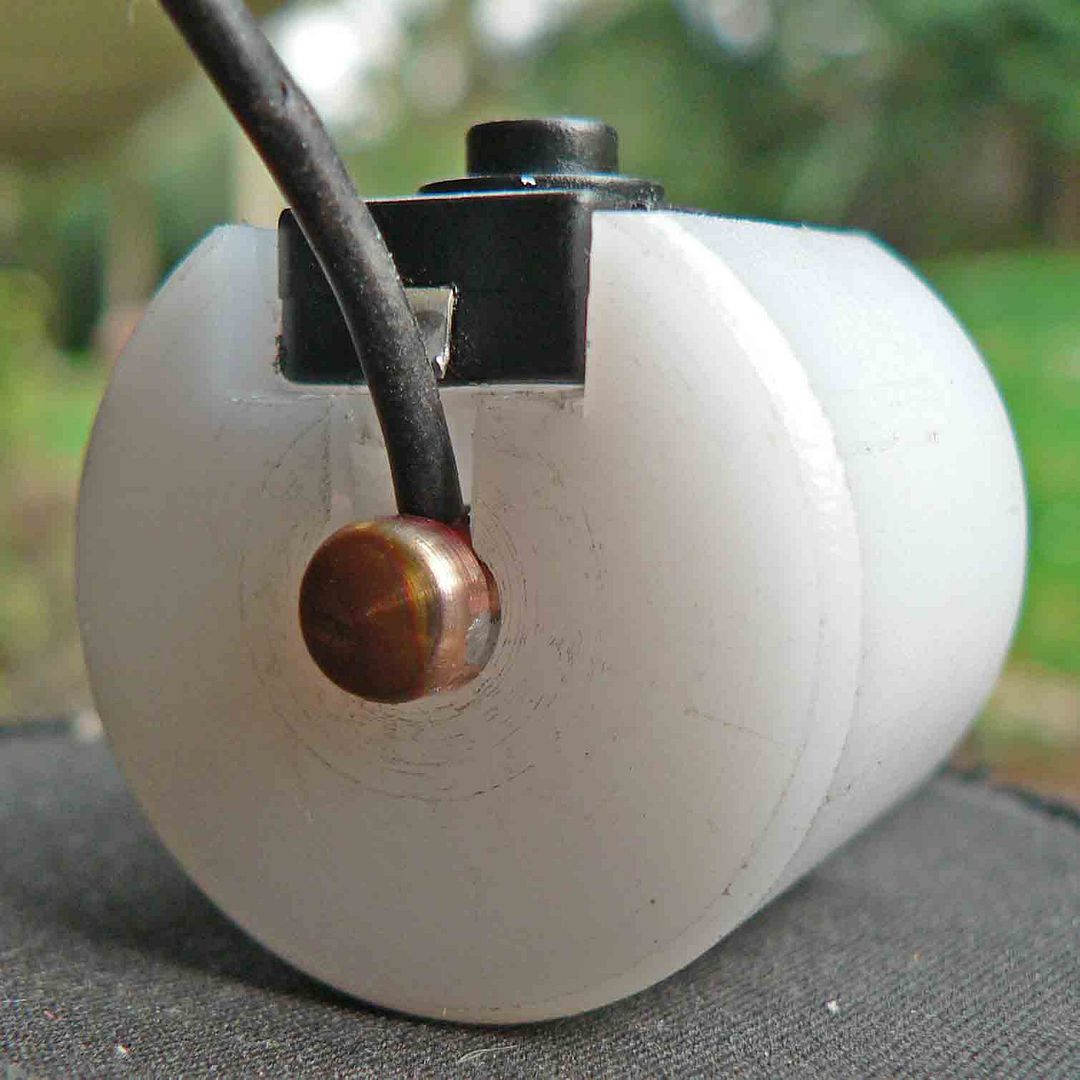
And finally fitted inside the flashlight housing.
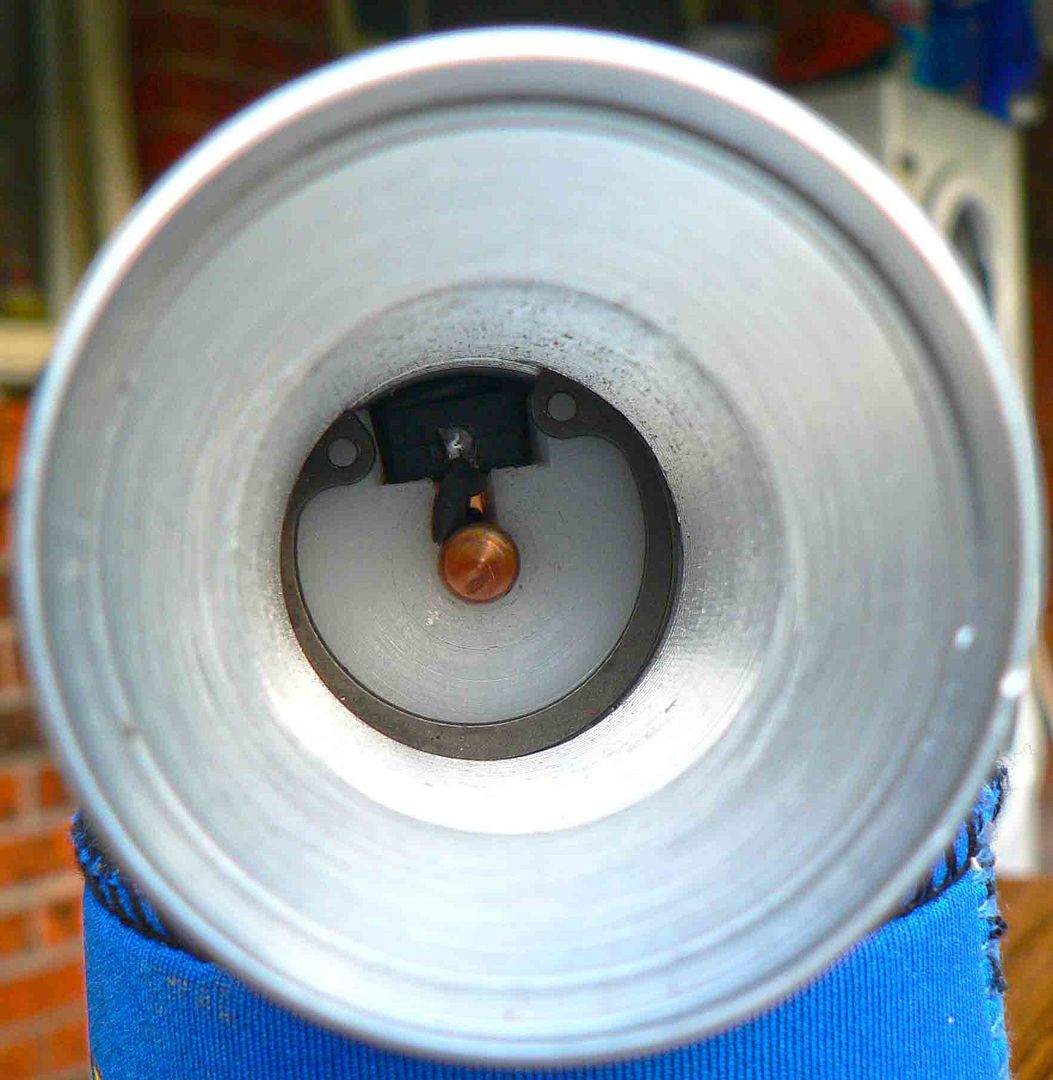
The bezel is made from a piece off scrounged brass. Problem being I don't have any to make a tailcap with. I'm not sure what I'm going to do there yet.
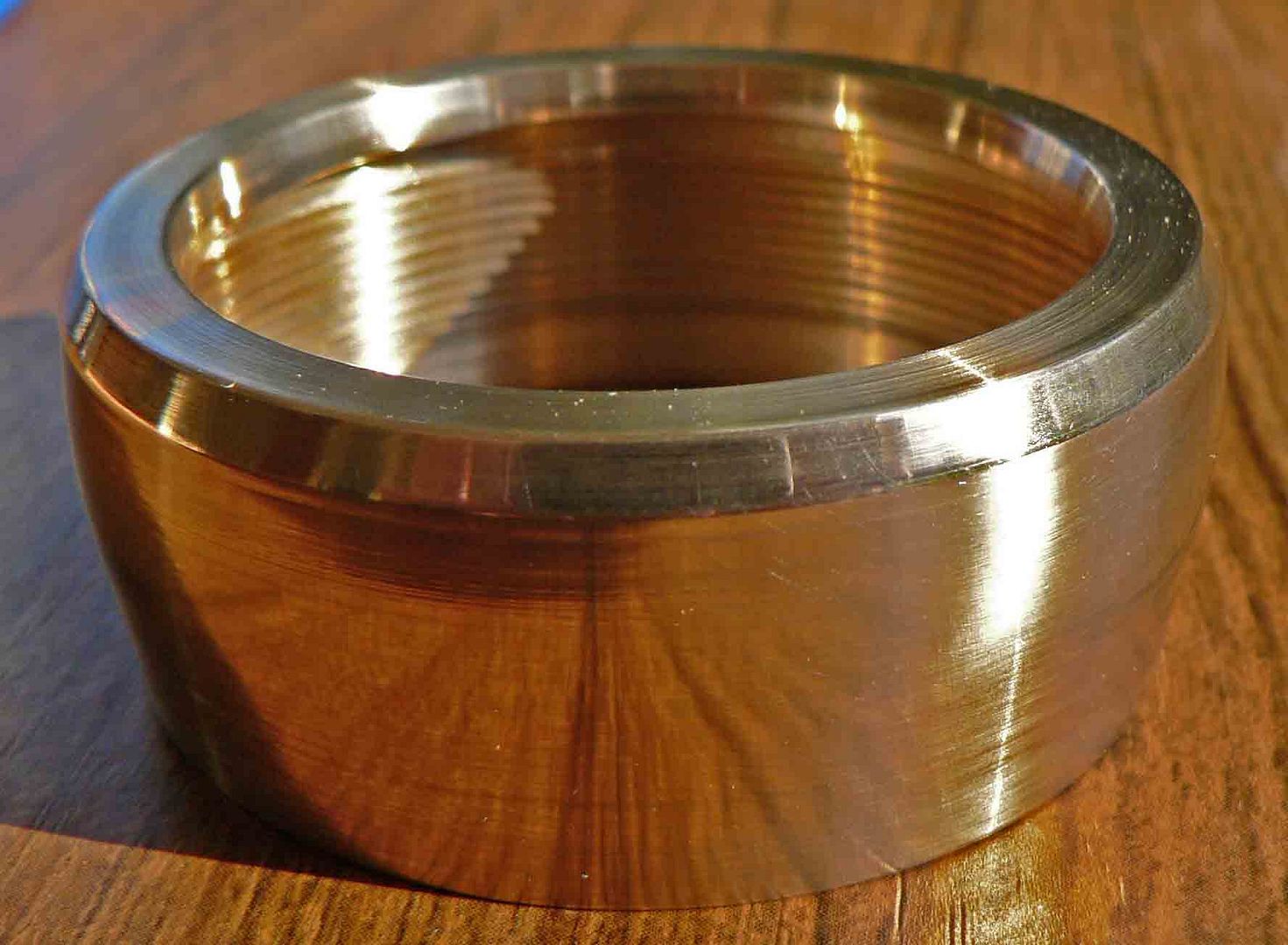
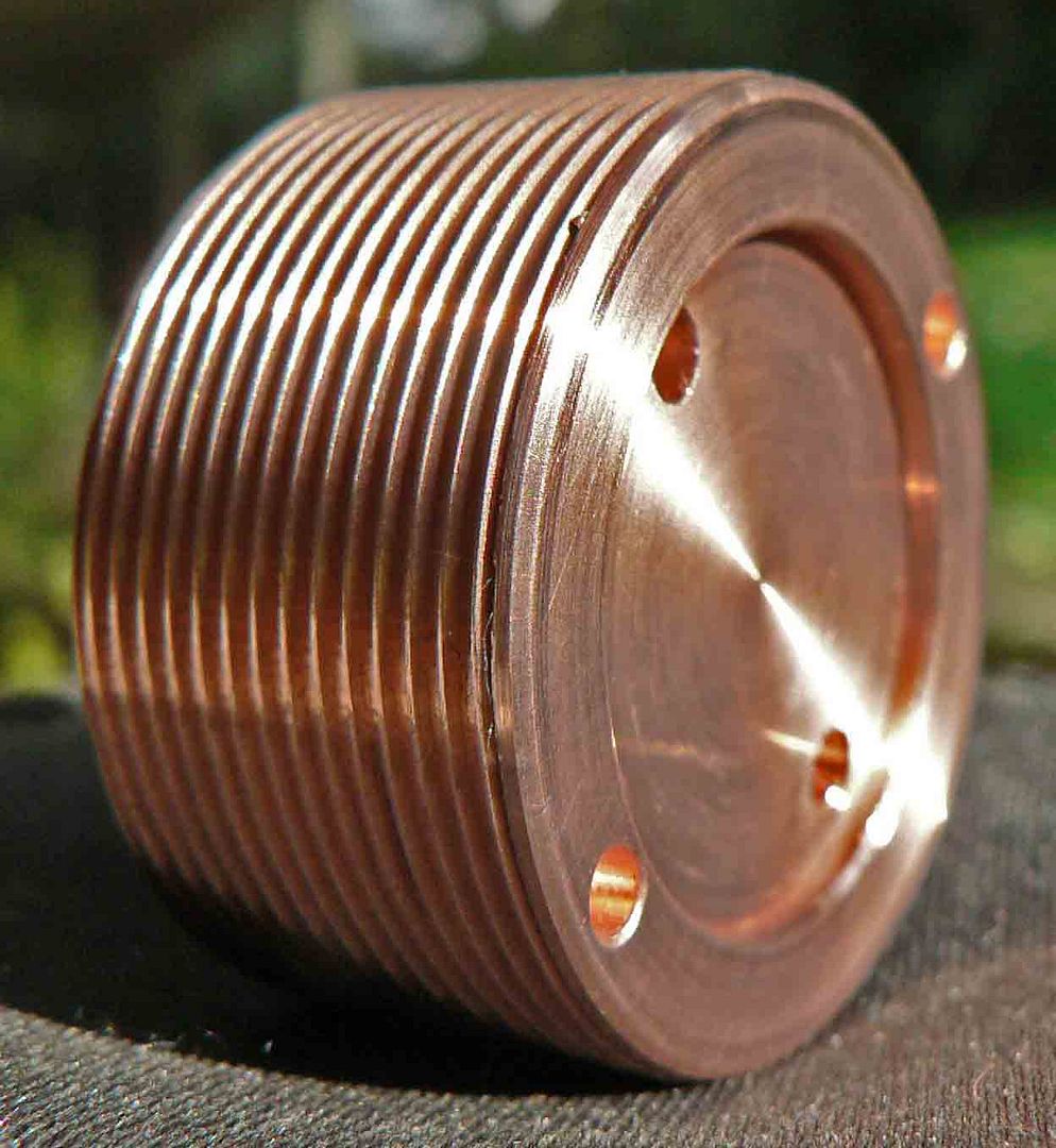
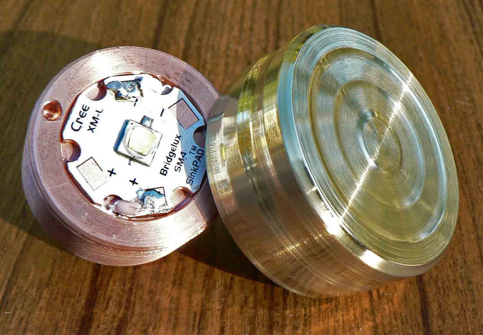
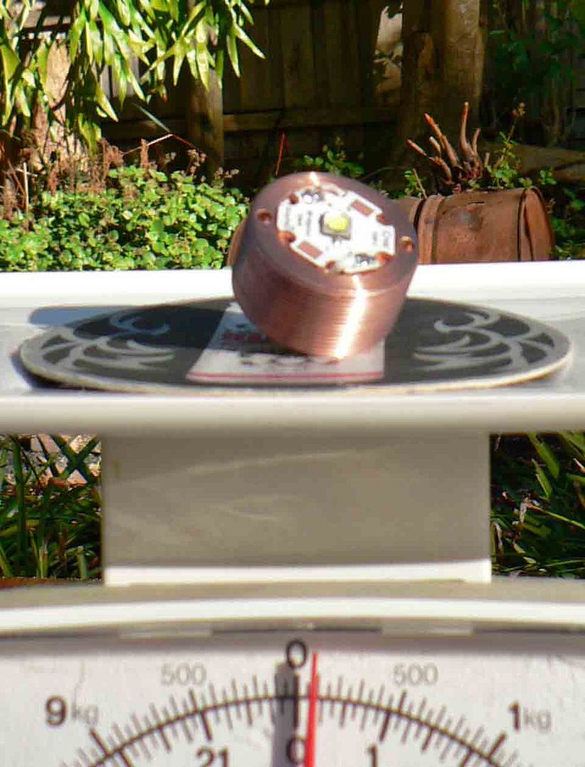
The pill is massive which is made from copper. This light will end up weighing as much as a brick. Thread size is 30mm. Driver diameter is 17mm and the depth of the hole for the driver is 11mm.
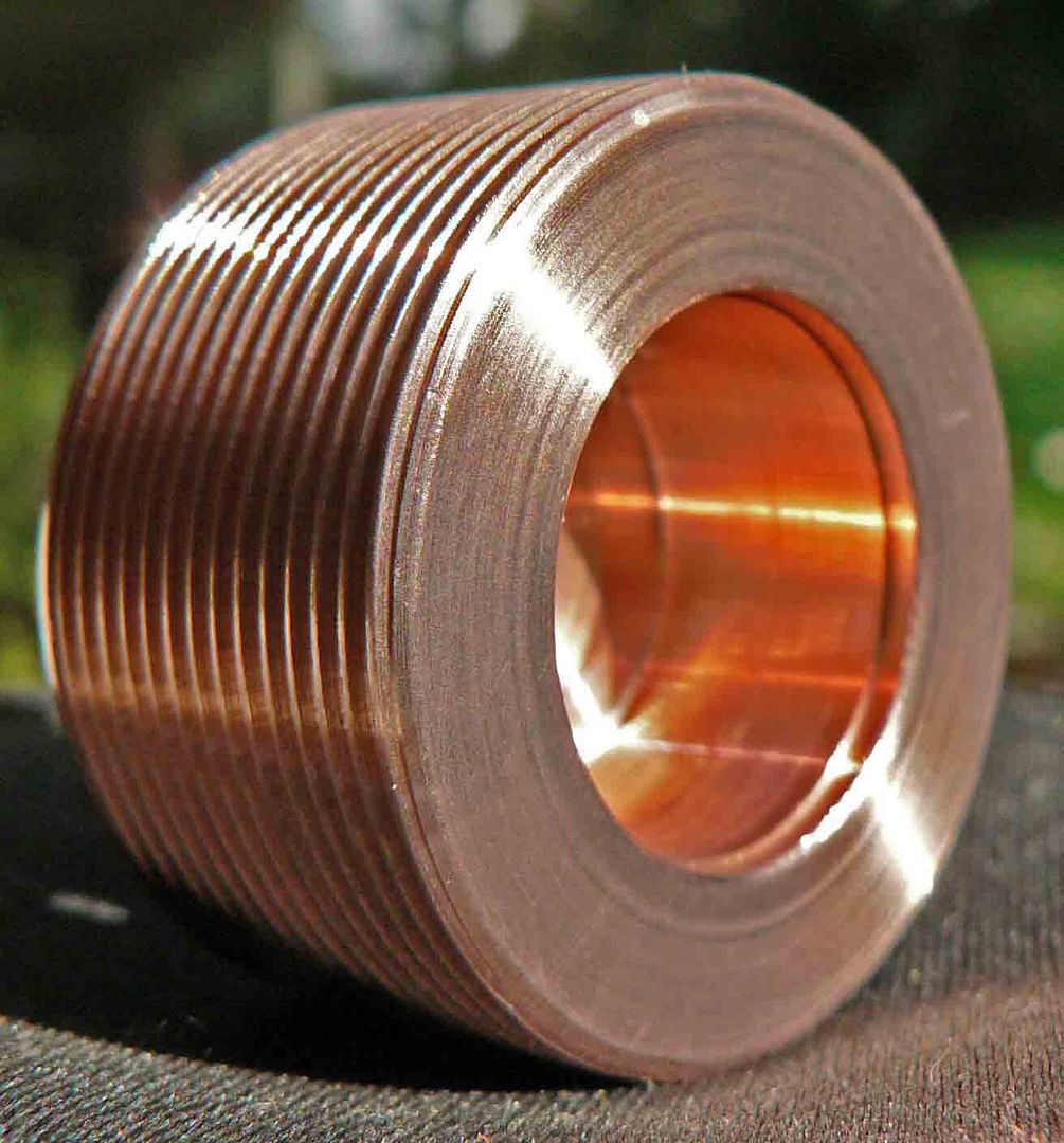
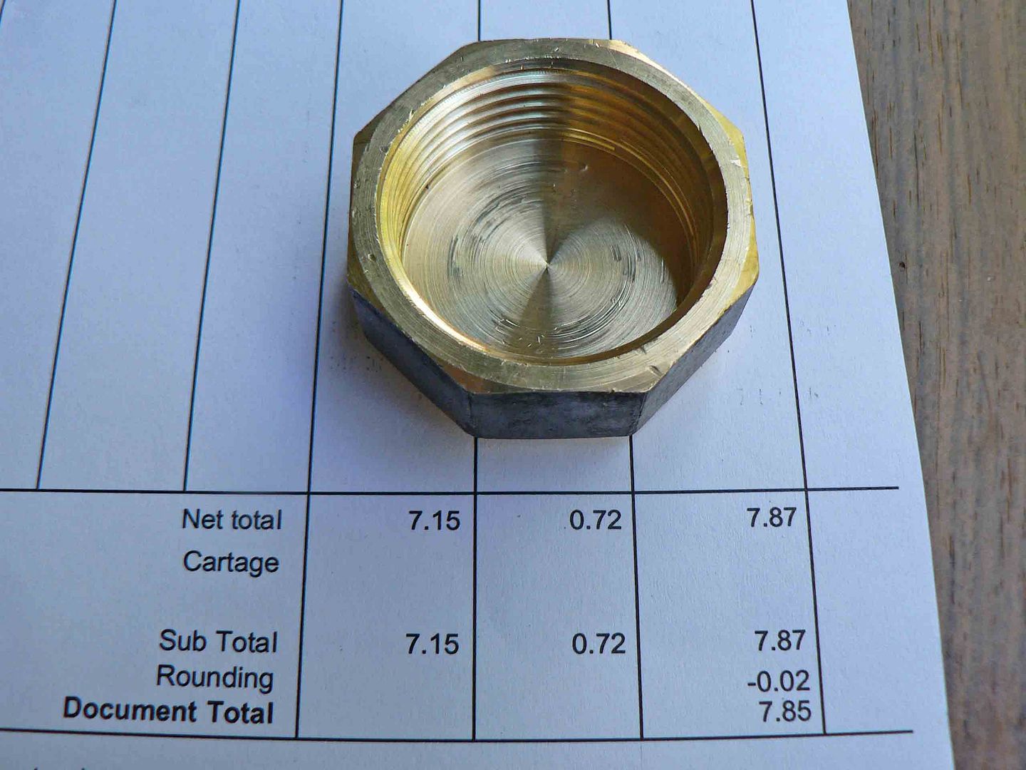
Nearly done. I may get disqualified for this build as I cheated on the tailcap. I took some homage from the hand built lights and visited the local plumbers in desperation for some brass coming away with this. A 1'' BSP cap. Its not correct but I will explain tomorrow in my summary. This hurt.
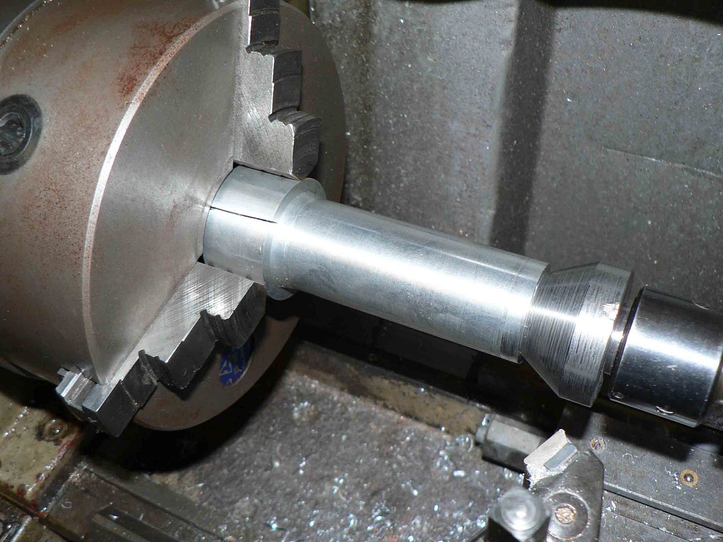
There was not enough material left on the head of the light to hold it while the tail end was being machined so I made a split bush to hold the body in the chuck and a large taper adaptor to go over the live centre to steady the light.
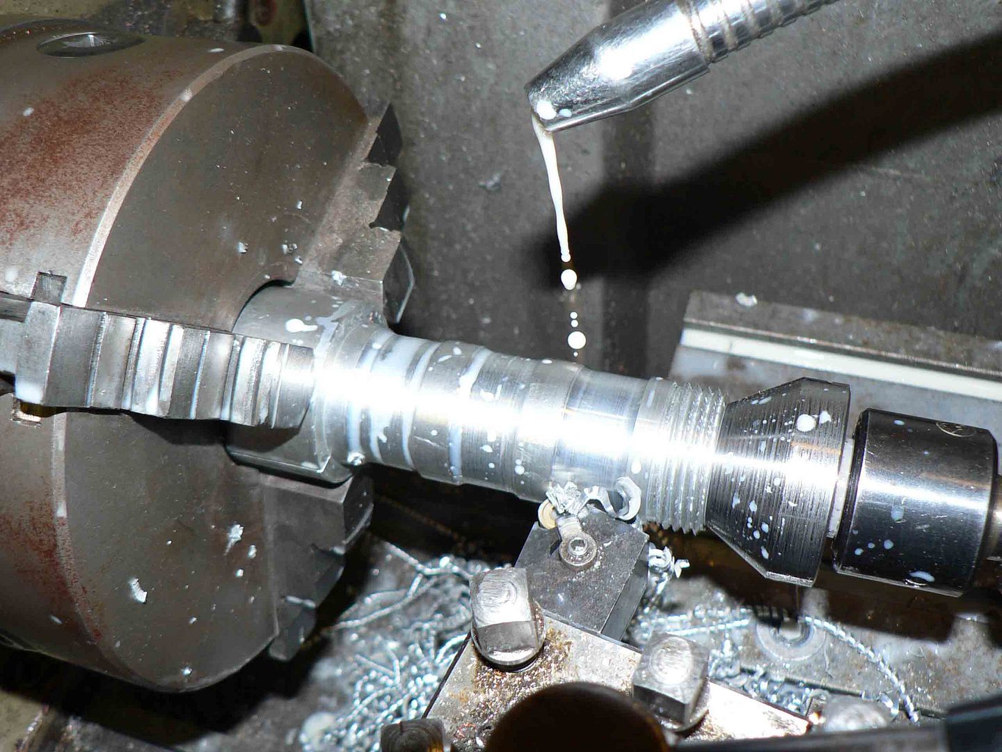
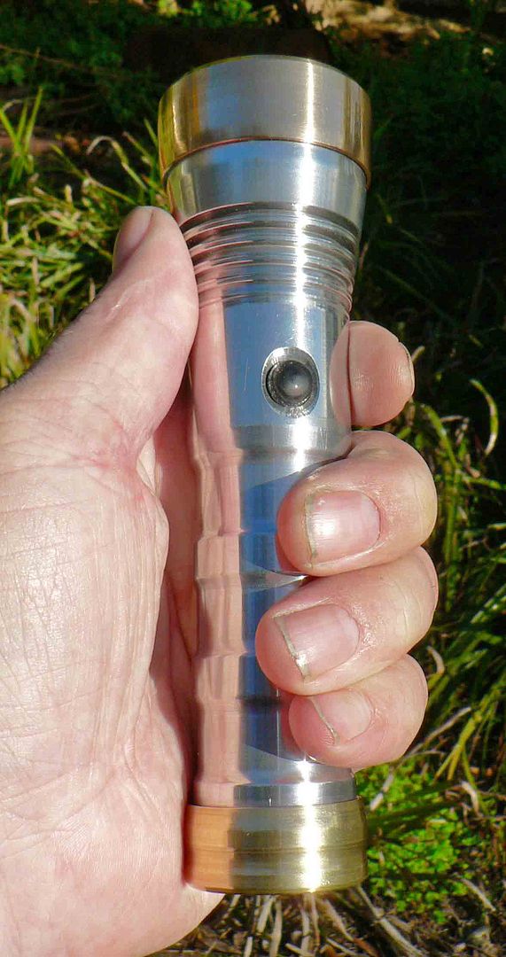
I did not want to use knurling on this light and spent a lot of time wasting material to come up with this design. Each individual groove suits my fingers holding the light. It does not work for Mrs DNF.
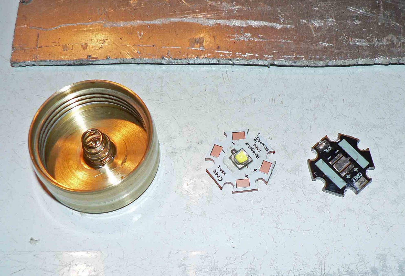
Mrs DNF left for the afternoon so I could use the stove without getting in trouble. The two pictures are before and after.
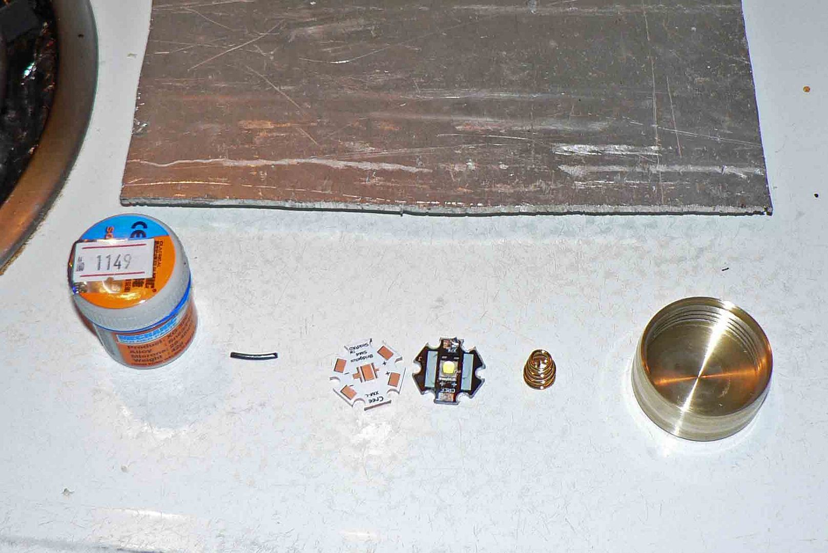
Thanks to OL for answering a question I asked for me being able to solder the spring in neatly. This has since been changed but soldered in the same way.
A picture of all things copper and brass.
The finished one piece housing.
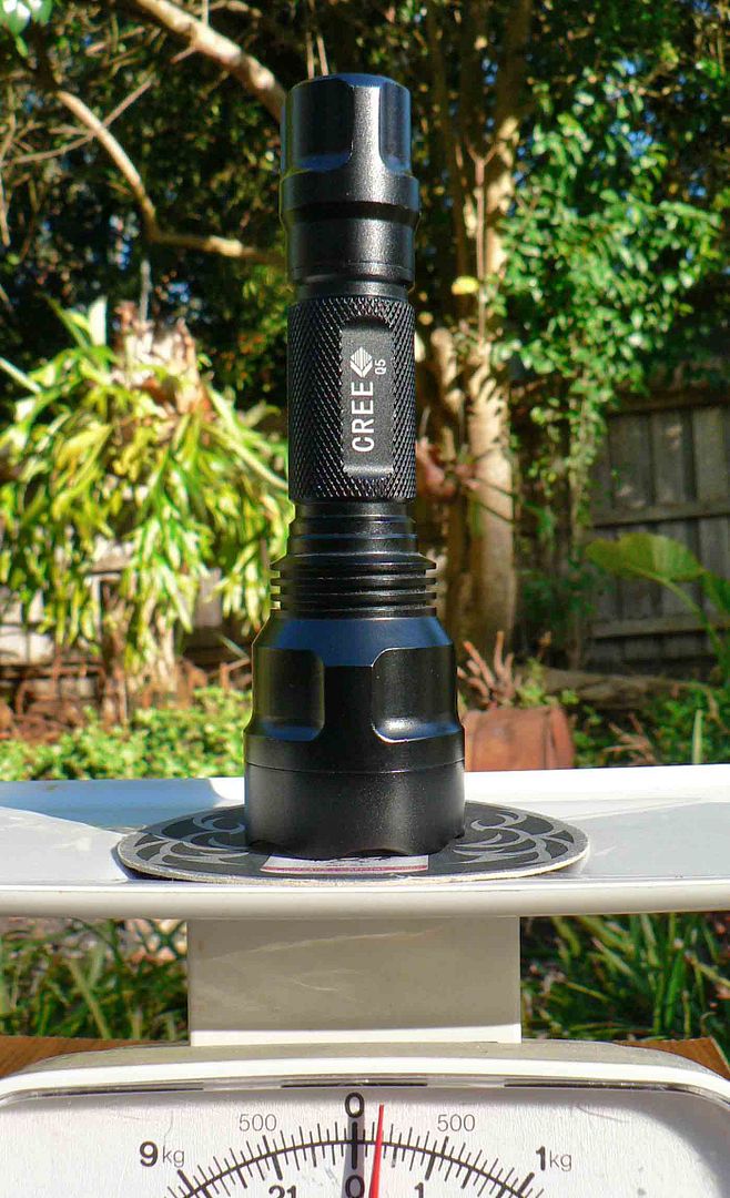
A couple off pictures showing a stock C8 weight and the weight off the pill alone in this light.
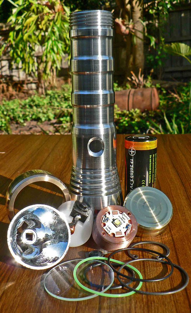
And finally a family portrait all the parts that went into this light.
Some night shots. Firstly a C8 running 3 amps and a XML-U2 cool white led that is not quite as bright as the XinTD V3.
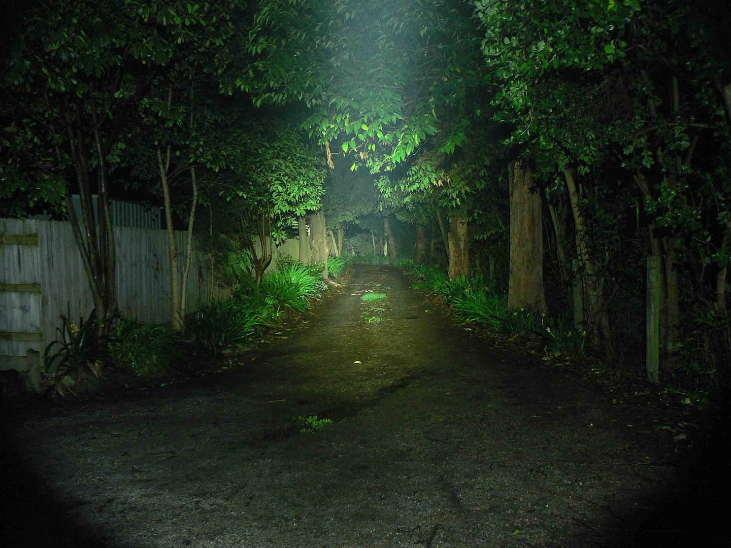
EA4W U2 on turbo.
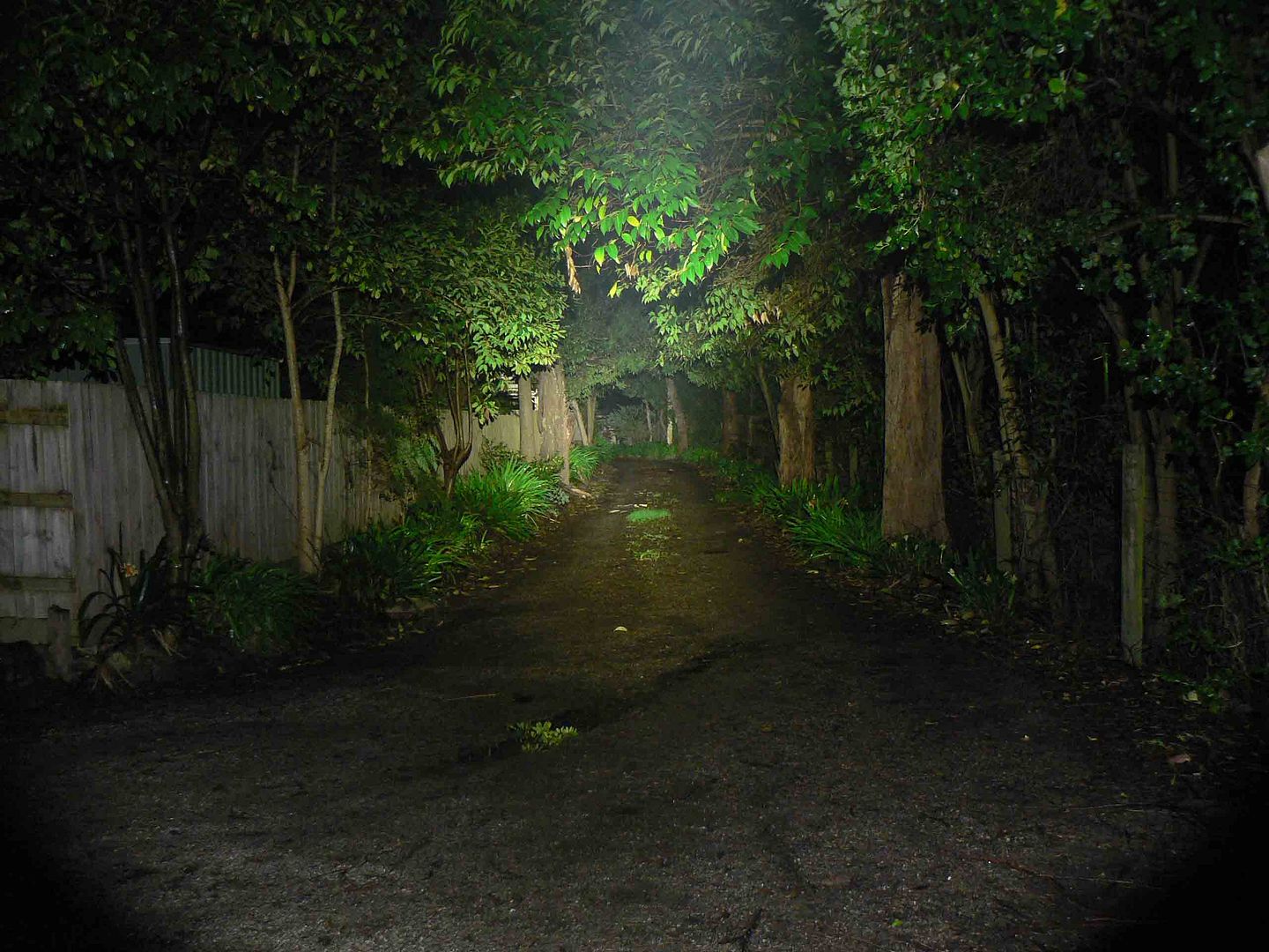
And finally this light running here at 3 amps with a filthy reflector that would not clean up and an XM-L2 T6 0A.
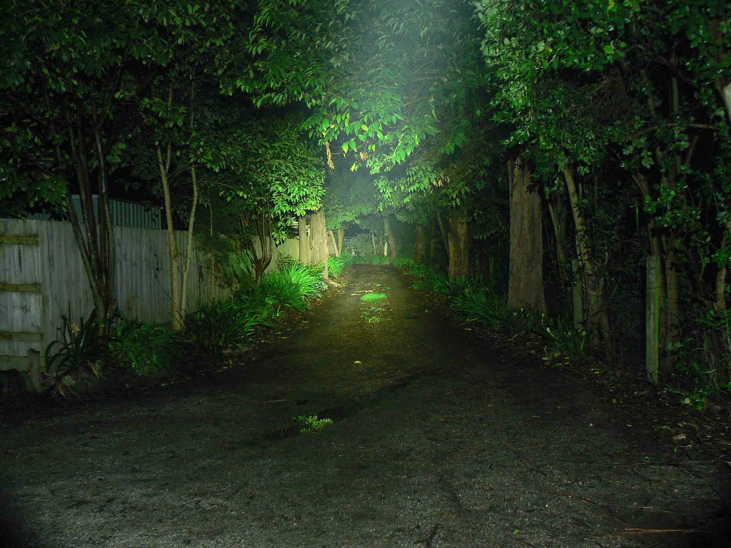
Mouse over this light. Mouse out C8 XML-U2 cool white. The tint on this light should be nearly blue but comes out a lot warmer than the XML-U2. The spill is also a lot bigger on this light contrary to what the pictures appear to show. The reason for this is that the hot spot on this light is a heck off a lot brighter drowning out the spill.

An awkward hand shot showing the finger grooves in action.
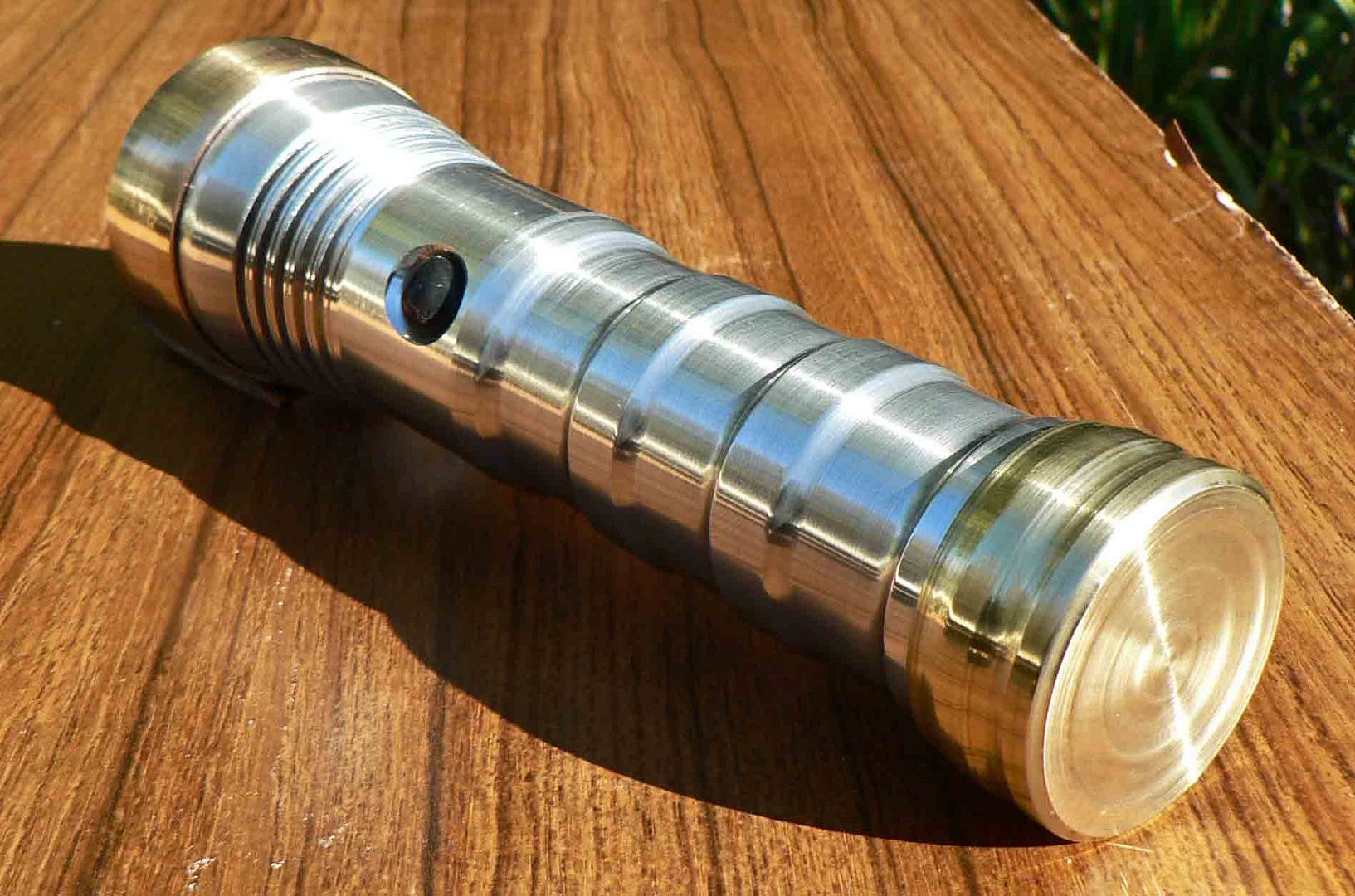
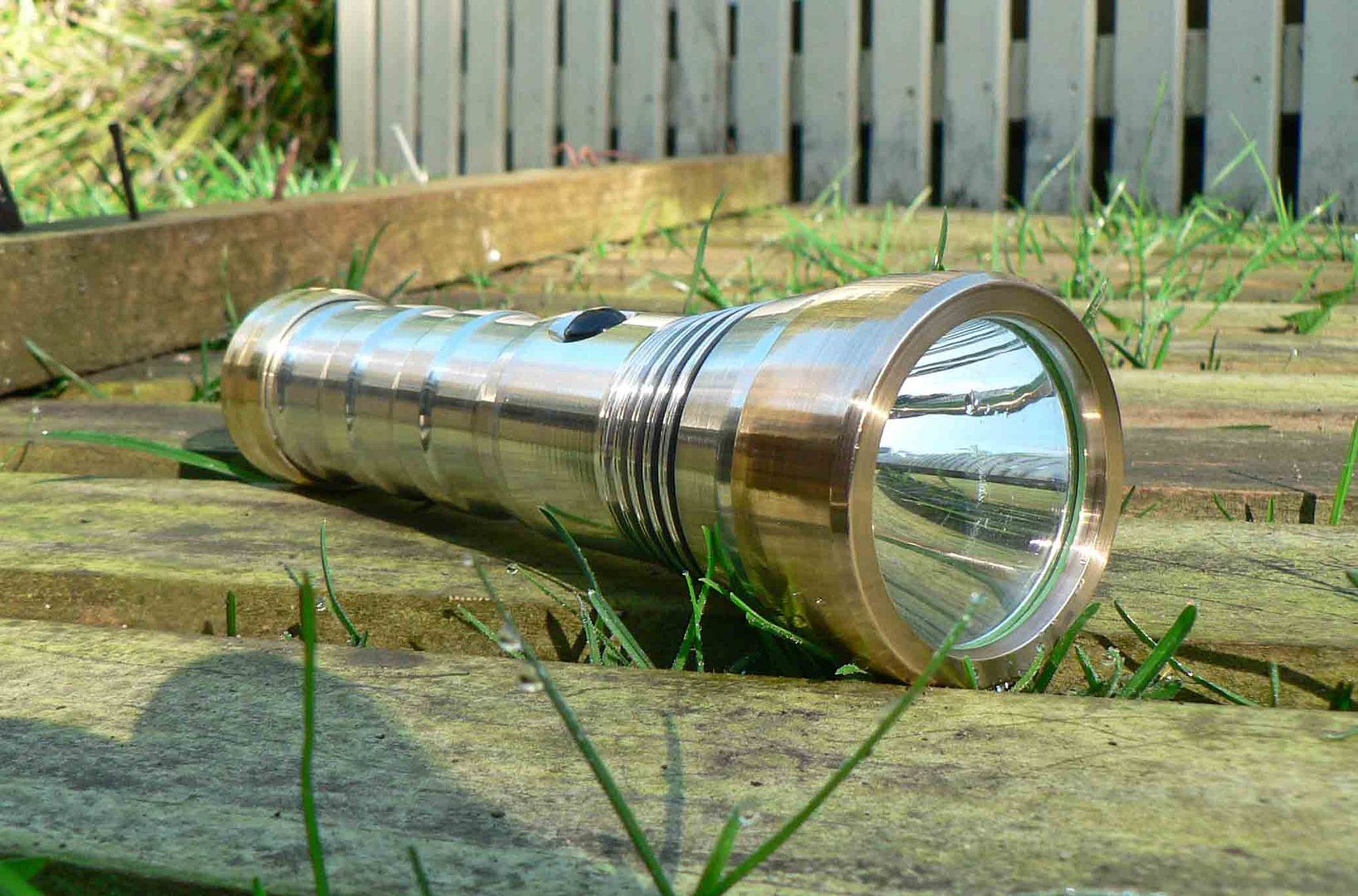
And lastly a couple off pose shots.
Summary.
I did run times on this light to test for efficiencies. My measurements dont relate to anything but this light. Ambient temperature was 19 degrees C. My educated guess was the light never got above 55 degrees C. The whole light pretty much heated up over the whole length. With a ceiling bounce test run over an hour the initial reading was 32 lux which pretty much dropped in a straight line to 24.1 lux. After letting the light cool down to room temp it was again switched on with an initial reading of 24.8 lux dropping to 24.1 after 10 minutes. I dont believe that heat is causing the light output to change much at all. This driver will eventually be changed for a 7135 driver with a couple off extra chips added and a new reflector fitted.
The light itself to me was a challenge to build for more than one reason. Normally I just build a light. This time I tried to style it and spent far to much time trying to make the light look right. Machining a mm here and there and putting grooves here etc etc. At the end of the day I'm as good at styling as I am at soldering. The forward switch was another challenge which I thought would work perfectly with this driver. For some reason the driver puts out 3 amps at start up and gradually drops off with voltage. The other six hundred and fifty five modes are not there. Well they probably are but there not coming out to play. The switch though works like a dream. Yes I am a fan.
My search for the elusive piece of brass was in the end mistaken. When polished up the bezel and tailcap where different colors. Foolish me. The material I thought was brass I made the bezel from was bronze. So it has an aluminium body, bronze bezel, copper pill brass tailcap and ended up with a weight off 340 grams.
Thanks for reading guys and again thanks to OL for putting this event on. I'm excited about what else will be machined up from my fellow rivals and as mentioned a couple off times blown away by all in the hand built category. Well done fellas and thanks for showing us your talents.
