I have made a triple channel RGB D1K using mostly off-the-shelf parts. Did it some time ago but don’t think I remembered to post it.
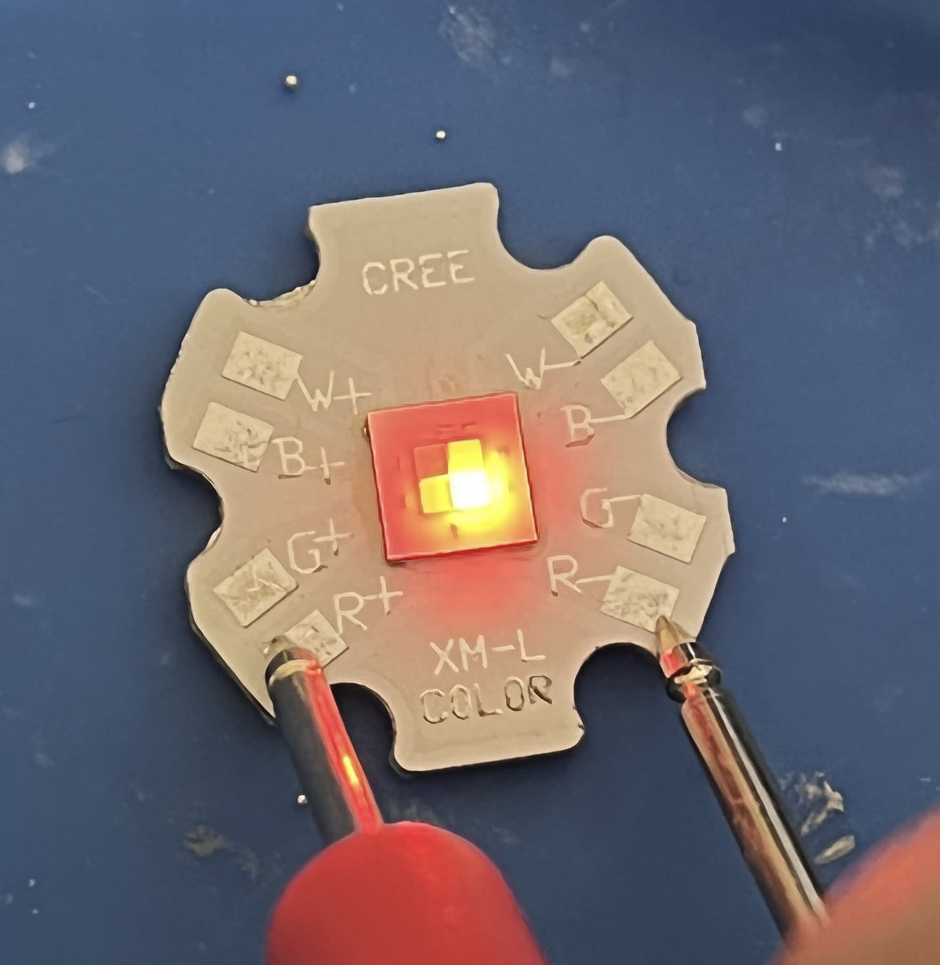
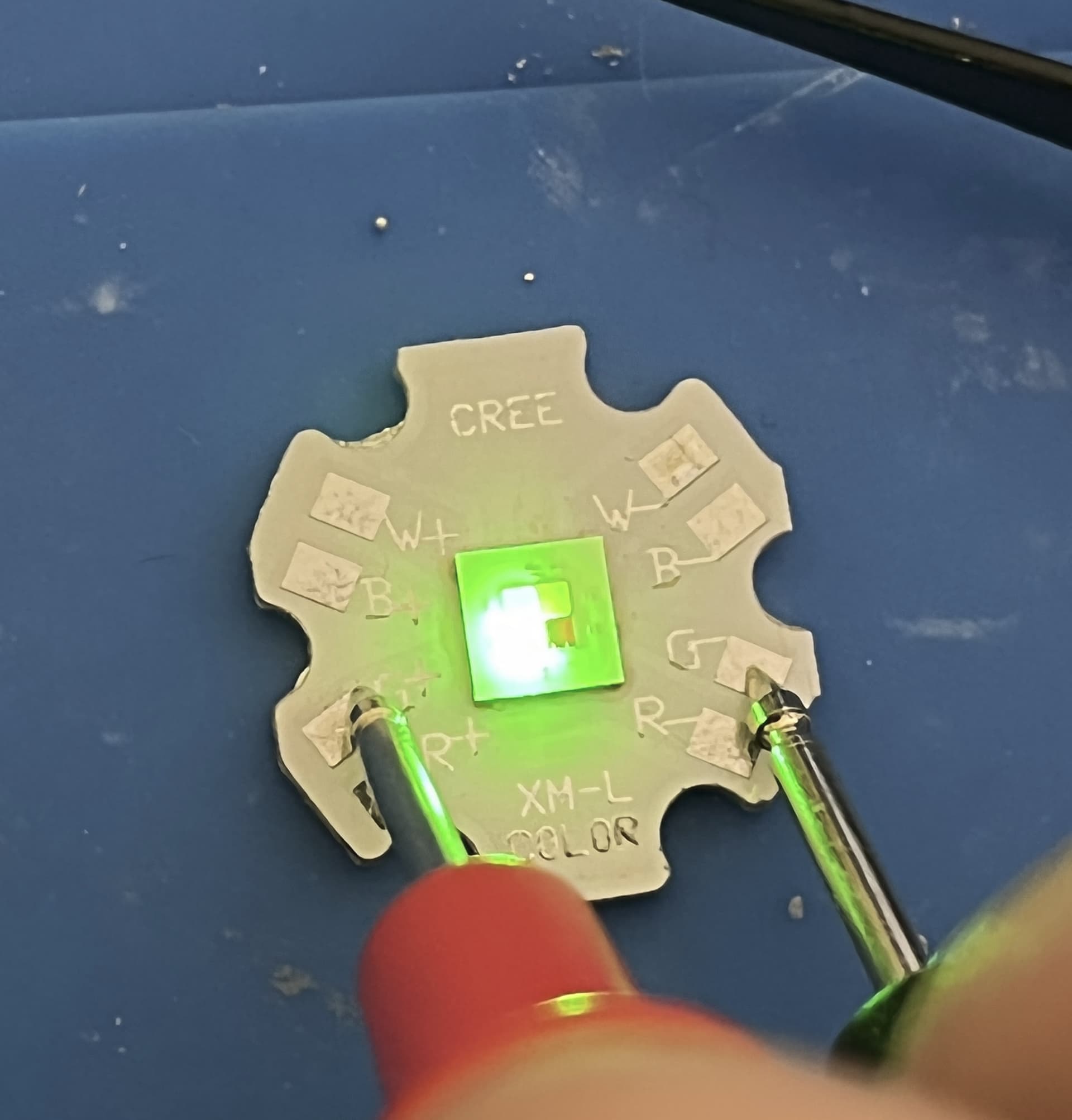
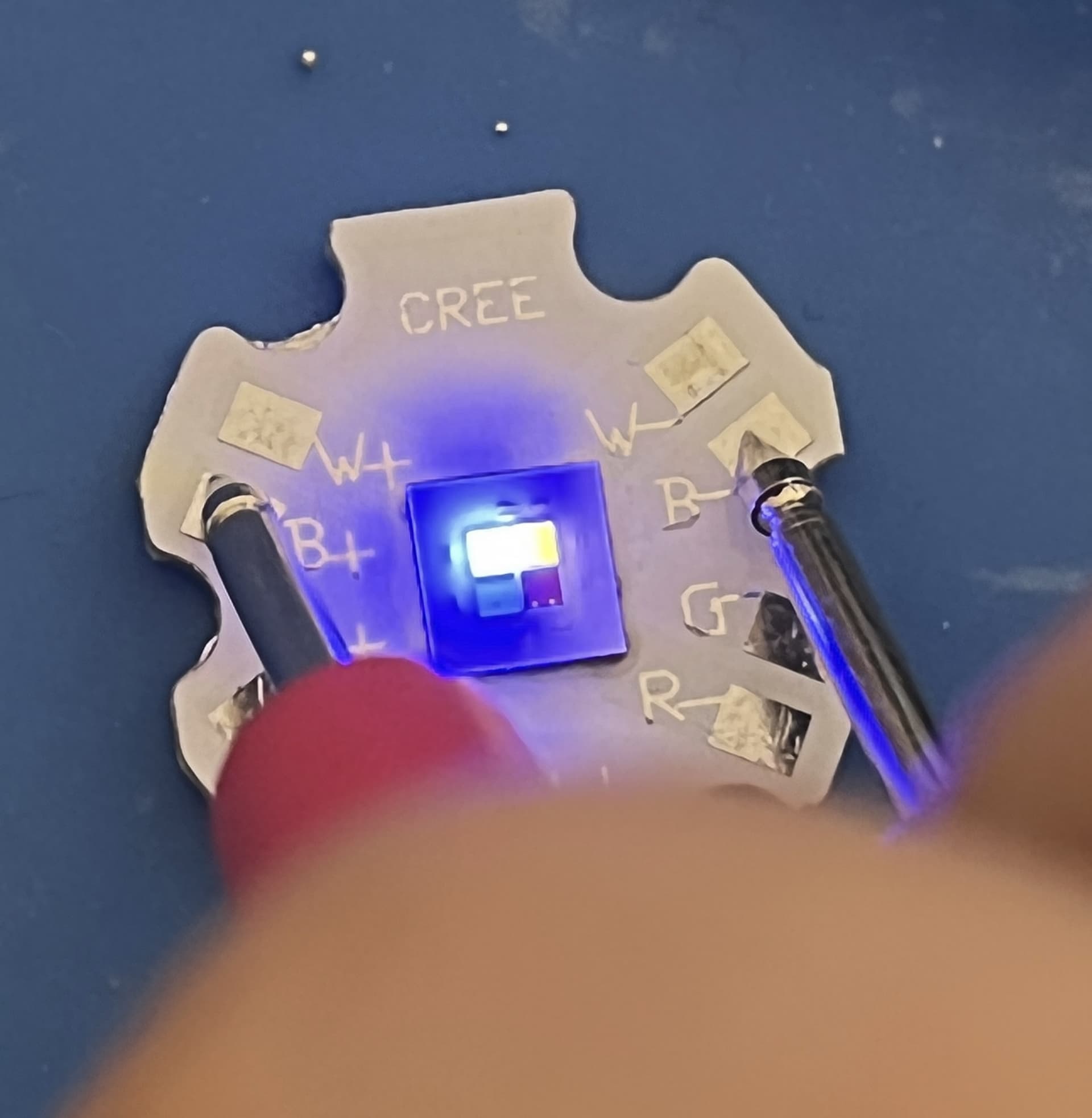
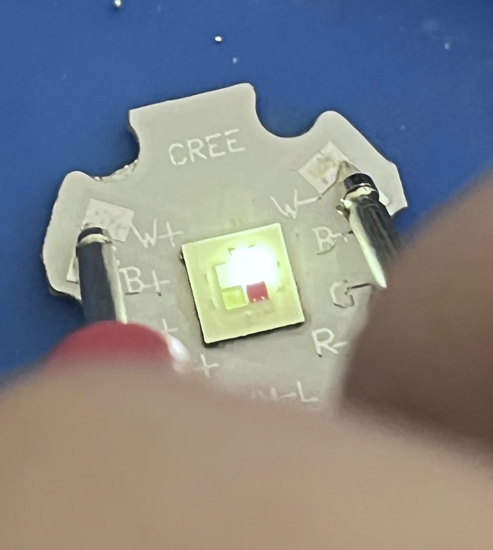
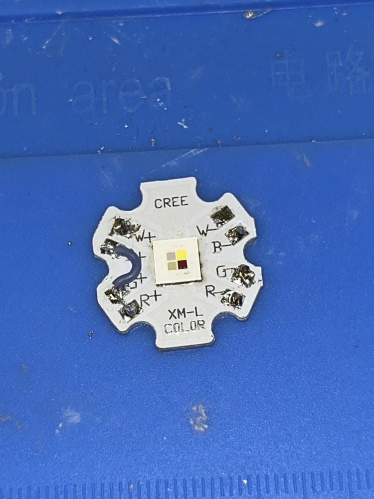
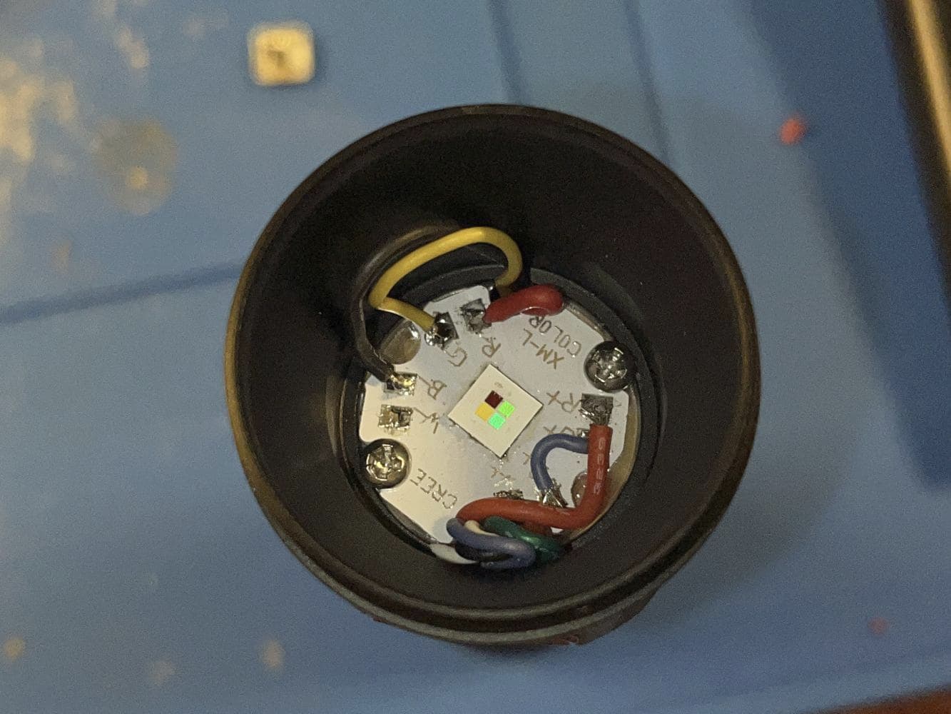
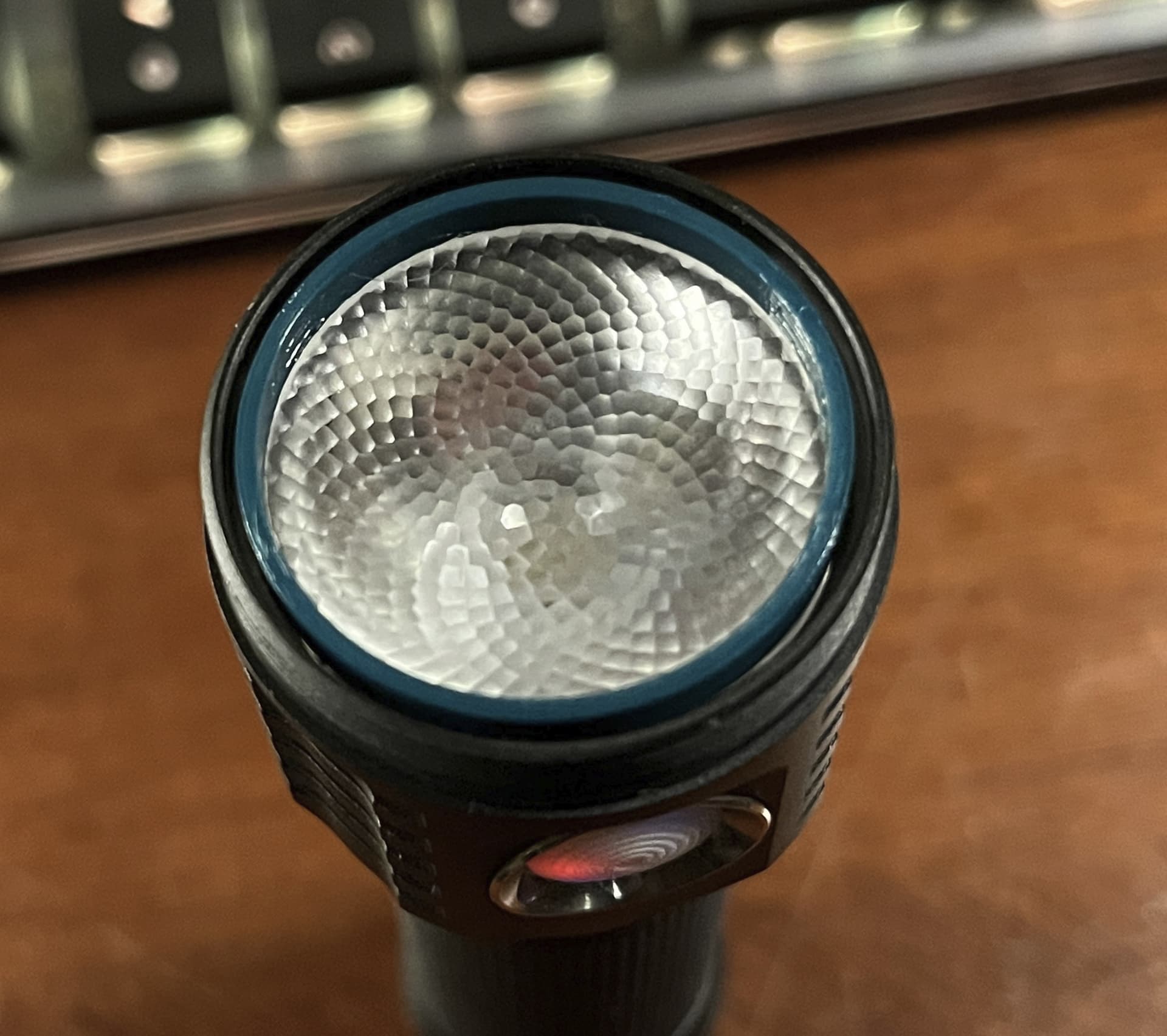
Used an XM-L Color G2 HI (RGBW but white is unused) from Digikey (4000k version) and a Ledil Olga-M optic to smooth out the beam, and connected the positives on the MCPCB with a scrap bit of wire. One of the pads ripped off the original switch so I used a spare where one of the red aux leds was broken.
Build pics below
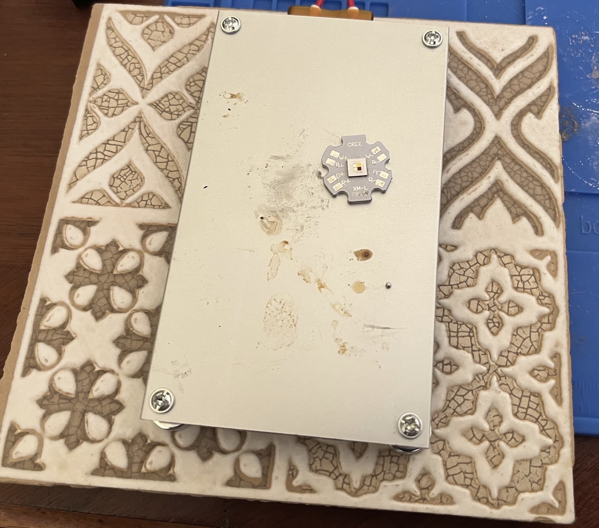
Reflowing the emitter. Used a ceramic tile to protect my desk from the heat of the sketchy hotplate. Worked good and was cheap.
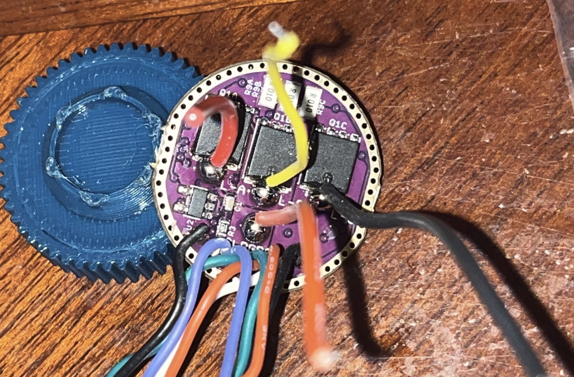
Driver pic, because I don’t think anyone had posted the other side of a 3ch driver. Also note the wire colors and labels (red=A, yellow=B, black=C) This driver was custom ordered to be 2.5A per channel, it looks like all 3 sense resistors can be swapped out without removing the driver from the light, pretty convenient for anyone modding a D4K 3-ch in the future.
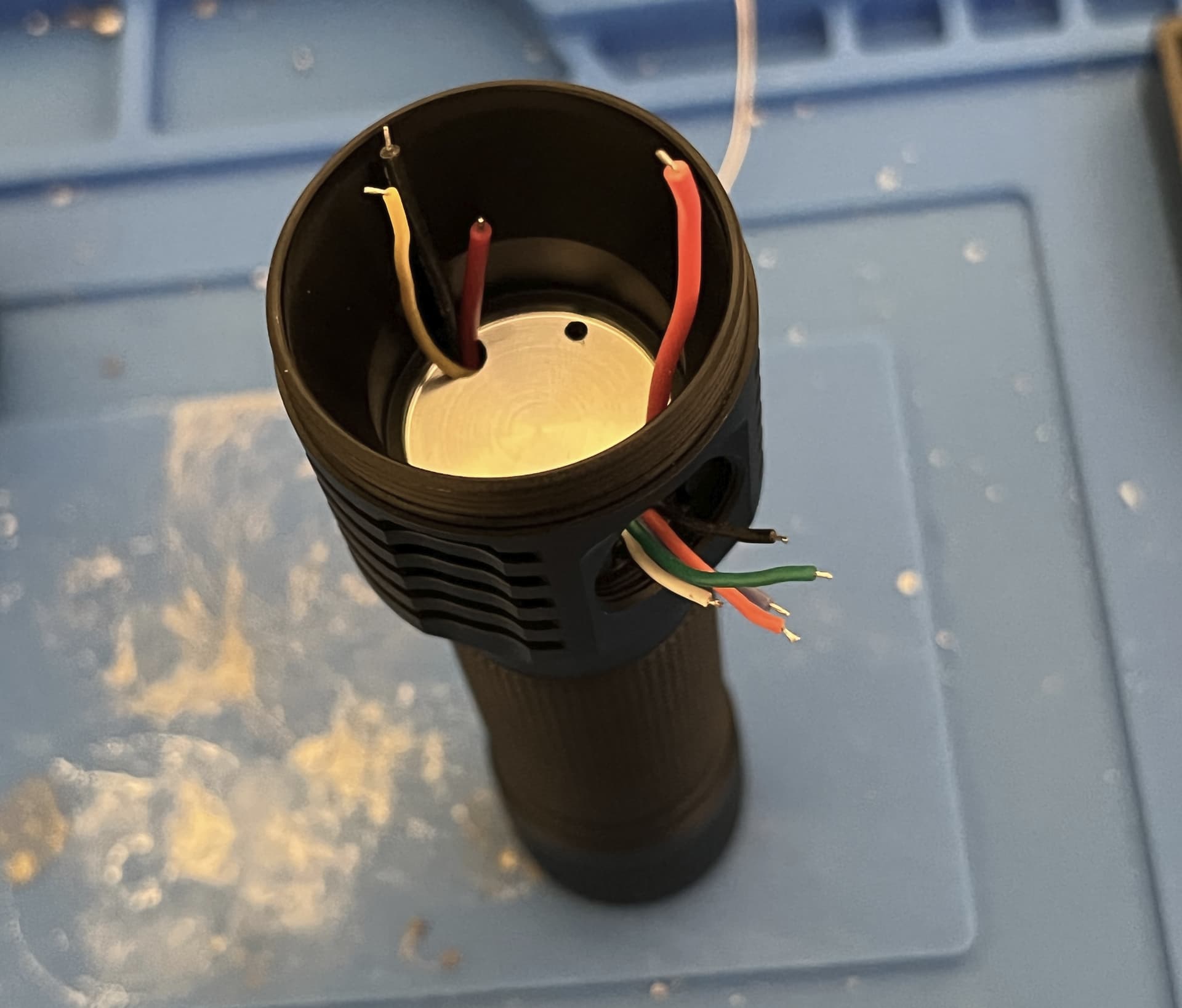
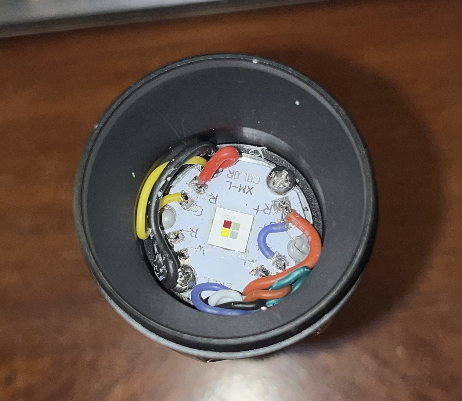
Was pretty tricky to fish all the wires through, but I was able to get it done eventually. My plans to put an RGB Aux board on it are pretty much done for though, unless I got comfortable using much-thinner teflon-coated wires
Positives connected in common. Eventually I touched it up to get a better connection between R and G.
Semi-finished light, with all the soldering done for now. Not my neatest soldering but it was pretty tricky either way.
Eventually I had to tuck the wires neater so that the optic could sit all the way down and focus properly. I 3d-printed a ring that acts as a spacer and holds down the optic in the host. It is made of PLA+ but the light doesn’t get very hot so it should be fine, seeing how it’ll only draw 5A at most.
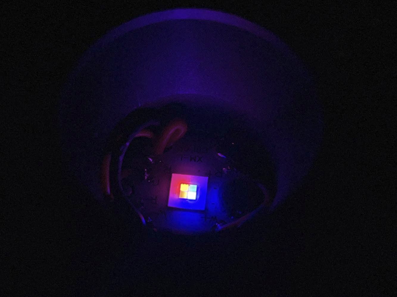
Don’t think I remembered to take final assembly pics or beamshots so I’ll attach them in a later edit. The color blending isn’t as good as I originally hoped, but it still works pretty well. It might become better with some DC-fix on the lens, but I don’t have any right now.
Random notes:
For whatever reason, when using stock firmware, going through the channels wasn’t RGB despite being soldered in the right order, the order when doing 3C being RBG, not sure why they are switched when using the default firmware. Either way, huge thanks to @wolfgirl42 for helping me by putting together some customized FW for this light.
There’s also a issue with the ramp shapes, but I haven’t figured out that one yet. I think it has something to do with 1 ramp being for dual-emitter and the other 2 being for a single, so when I switch from blue/green to red it gets a lot brighter, despite the moonlight being the same.
There’s also a few features I’d like to have, specficially one that synchronizes the color of the main emitter with aux, so that it too can behave like rgb aux (on moonlight). Another nice thing to have would be an auto-rgb mode that just keeps the light in hue-ramping.
EDIT 1: More pics