Lets look at the light first.
In comparison with some other "monster lights"
BTU Shocker - TK61 - OEM 12 XM-L light (largest multi-emitter head I know of)


In comparison with some budget throwers. (See comparison of popular BLF thrower favourites here. TK61 not included)
HD2010 - Big head COUROI - TK61 - ZYT08 - C8 (for size reference)
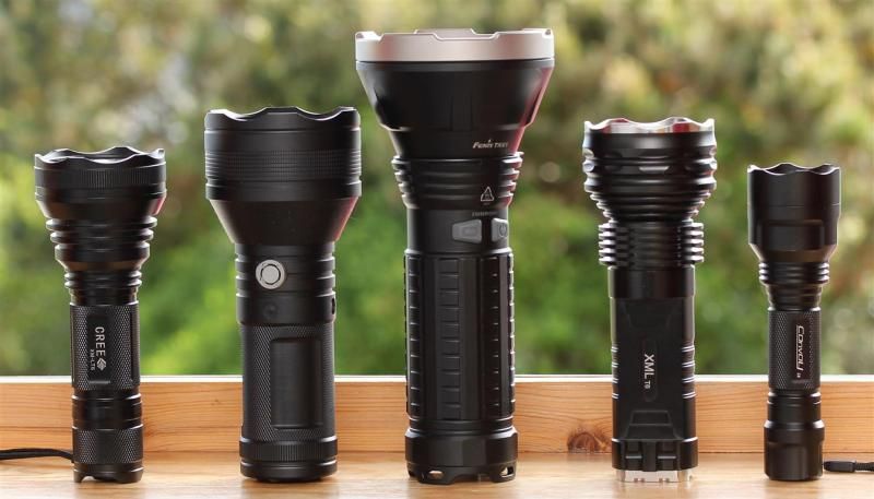
TK61 got moved one step to the left. See how tiny a ZY-T08 or C8 are beside it. :D

Some force is required to unscrew the bezel (very easy to unscrew with strap wrenches. Maybe not so with hand).
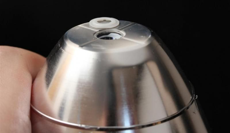
Then you can easily take out the massive plastic reflector.

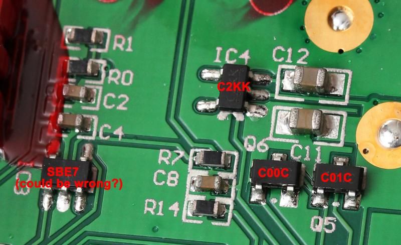
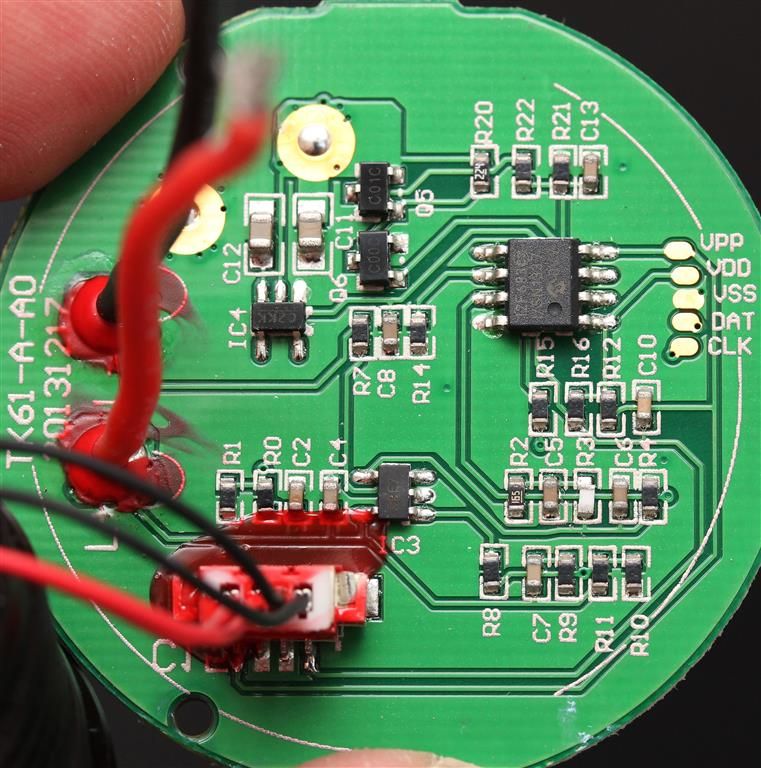
Contact board can fairly easily be taken out with a screwdriver. And you get easy access to the resistor where the magic happens. If you for some reason want to take the driver out. You have to unscrew the retaining ring and solder off the wires to the mcpcb.
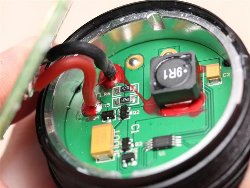
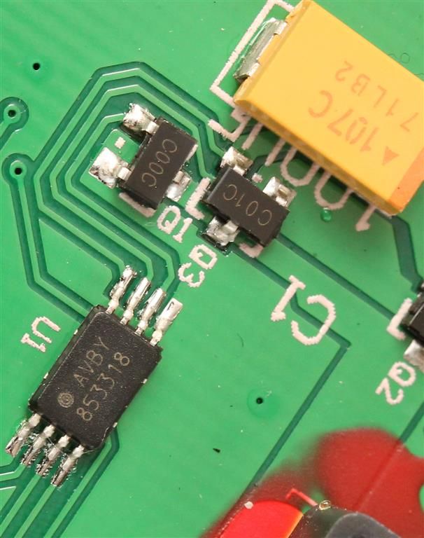
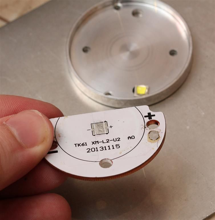
Close up top side.
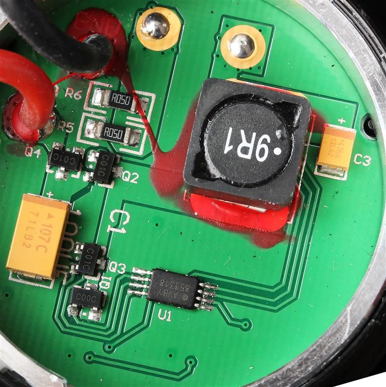
Another top side shot:
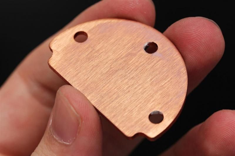
Underside:

The centering/locating ring seems to be special designed for the reflector. Its not a 100% perfect fit though. There is a tiny bit of sideways movement in it. Which was the reason my emitter was not 100% perfectly centered. More like 97%? Its easy to get the focus right by loosening the bezel a little bit. Pressing on the glass lens on the correct place should get it centered. Then put pressure on the middle of the lens and screw the bezel tightly in place.
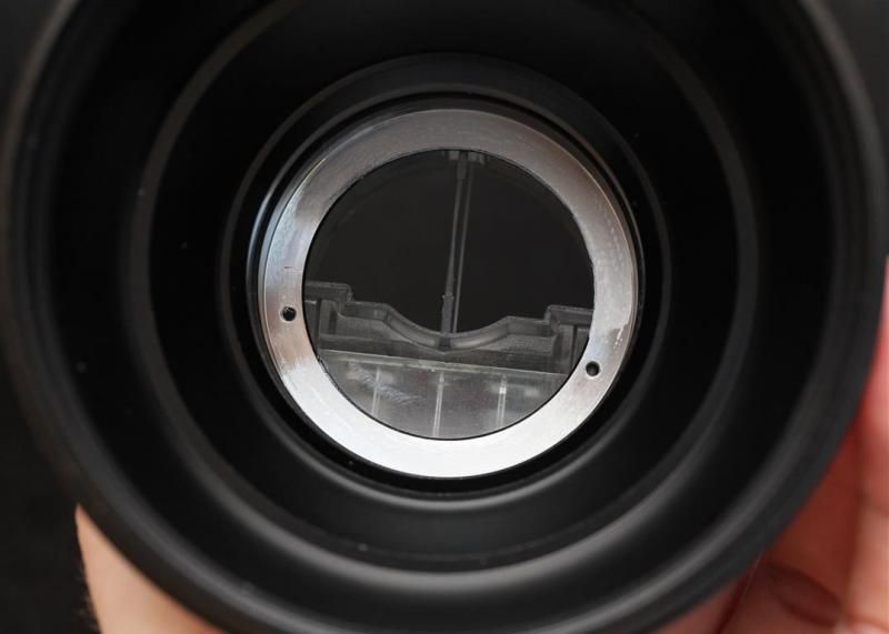
Reflector dimensions:
82mm inside reflector
86,7mm outside
Depth about 64-66mm

Pill was secured here with two screws. Thermal paste between body and pill.
Perfectly applied thermal paste. Pill is not that large.
6 mm tall
46,4mm diameter
2,62mm below mcpcb
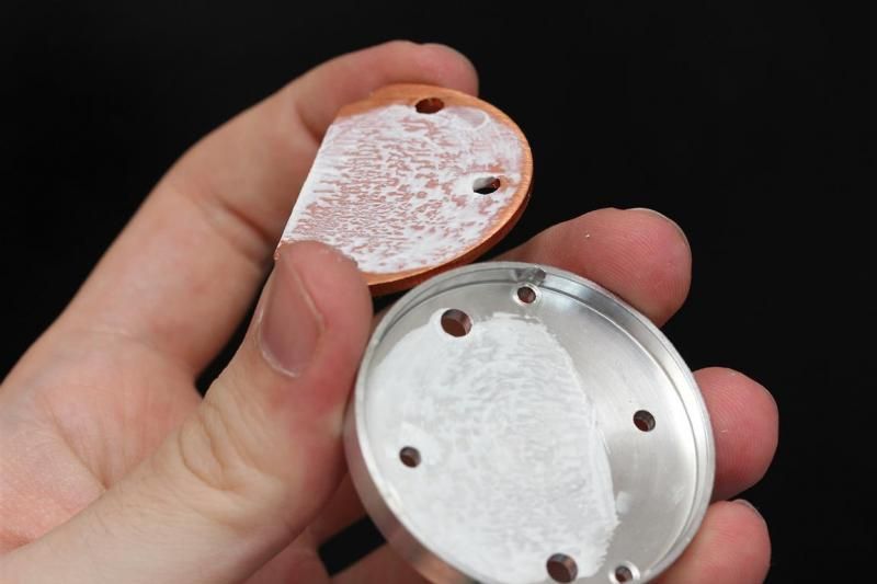
Measured contact between the center part of the mcpcb (below the XM-L2) to the underside of the copper mcpcb. Should mean its direct thermal path as far as I know. Like a Noctigon and Sinkpad. Seems like its similar to Sinkpad 2 in design. The copper mcpcb is 2 mm thick and 43,6mm in diameter.
Underside feels a bit rough. I lapped mine a little bit (not pictured). Its one beefy and heavy mcpcb. :)
Stock output:
Stock emitter current:
Low: 0,xx A
Medium:0,4 A
High : 1 A
Turbo: 3A
When input voltage is 8V, input amp is 1,6A on high. Emitter current 3A
When input voltage is 6V, input amp is 2,2A on high. Emitter current 3A
So this is nicely regulated down to 6V. What cells you use are pretty much irrelevant. 2,2A is divided on 2 cells. So you will not see more than 1,1amp drain from each of the four cells. Using high discharge cells are not important. Even after a little resistor mod.
The light cuts power when input is as low as 5,7-6v, so you can not use turbo or the higher modes depending on the voltage. At that point the cells should be considered empty anyway. The light will not cut off completely. The emitter sees power as long as input voltage is above 2,5v.
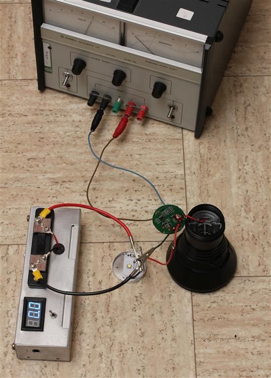
Here is my simple test setup btw..
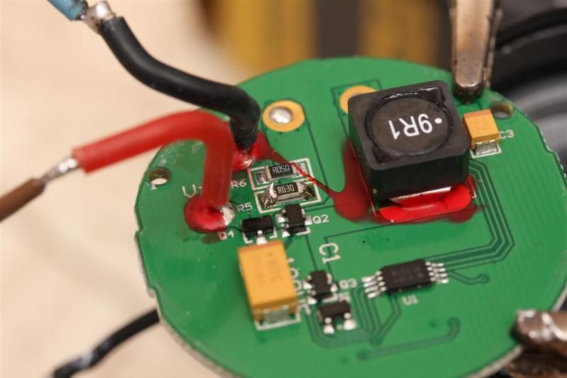
Resistor mod:
I added one R030 on top of one of the R050. (no need to take the driver out of the light)
Output after R030 was added.
Low: 0,1 A
Medium:0,6 A
High : 1,8 A
Turbo: 4,7A
When input voltage is 8V, input amp is 2,8A on high. Emitter current 4,7A.
I added another R030. Do not do this.
Low: 0,2 A
Medium:0,9 A
High : 2,4 A
Turbo: 4,8A
When input voltage is 8V, input amp is 2,9A on high. Emitter current 4,8A.
Summary/observations with resistor mod:
Based on stock values vs resistor modded with R030. It seems like all modes increased with around 50%, including Turbo.
Trying to push peak output further by resistor modding is not beneficial as it will not increase turbo any noticeable amount higher. Only the lower modes.
Stock lux reading was about 171kcd@ 30sec ("calibrated" my meter after this light). After resistor mod and a minor tweak to the centering of the emitter I was looking at about 255kcd @30 sec from the stock domed emitter. Measured from 10 meter and calculated back to 1m.
A dedome should bring it up to around 500kcd @ 4,7A emitter current.
NEED MOAR AMPS!
IF YOU HAVE ANY GOOD TIPS ON HOW TO FURTHER INCREASE OUTPUT. PLEASE HELP. My electronic skills are very limited.
Its said vinh gets 5,75A at the emitter and about 600 kcd out of his de-domed TK61 mods. It was said he changes transistors too?
Either way, I want 6A+++ and Im willing to sacrifice the driver in order to get there. So if you can give me easy DIY electronics tips ill do the testing. :)